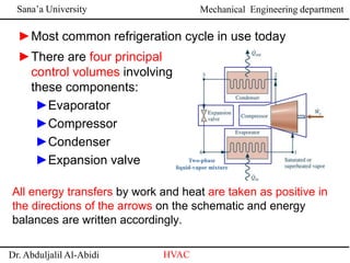
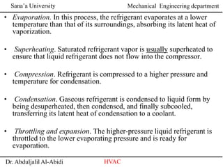
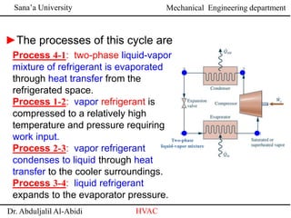
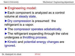
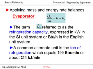
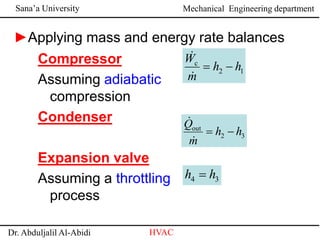
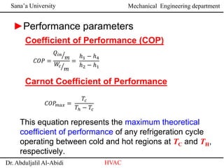
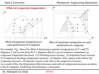
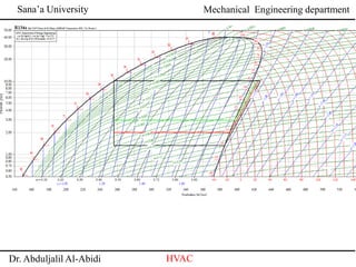
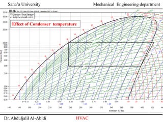
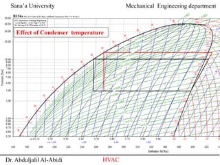
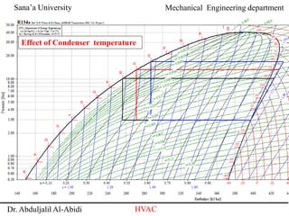
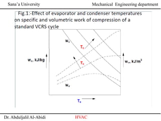
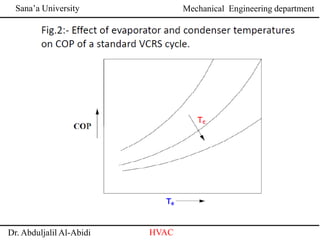
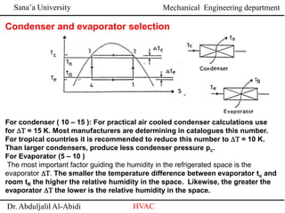
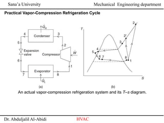
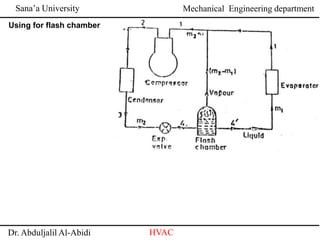
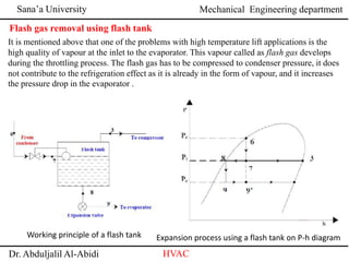
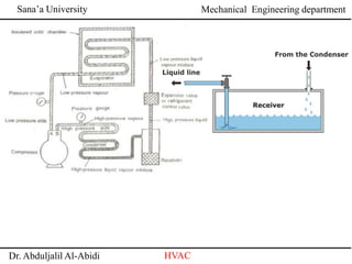
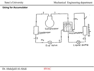
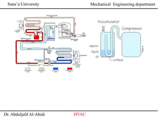
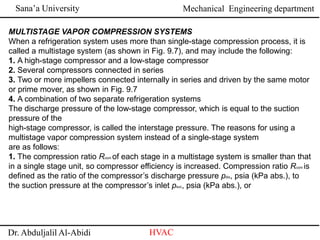
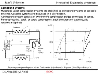
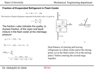
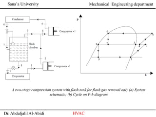
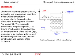
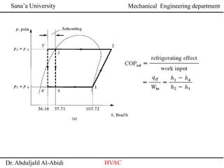
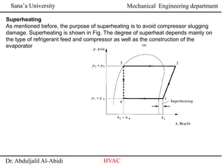
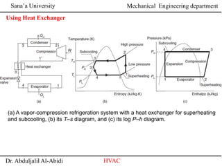
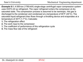
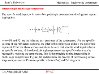
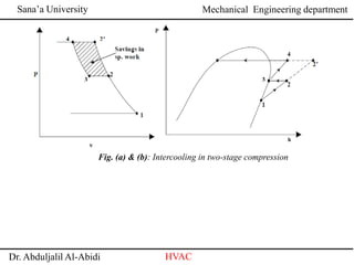
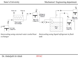
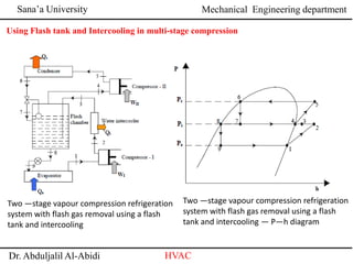
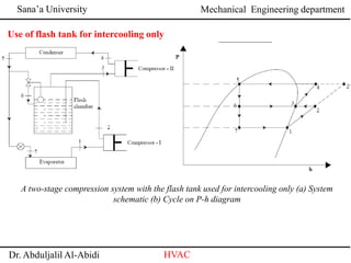
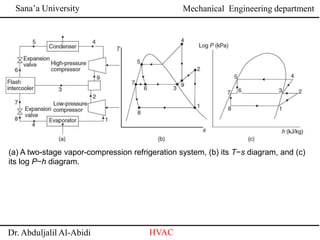
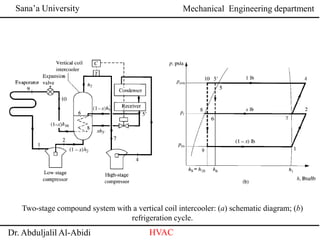
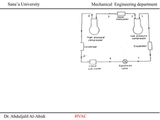
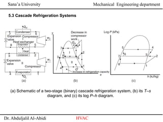
Sana’a University
Dr. Abduljalil Al-Abidi HVAC
Mechanical Engineering department
Vapor Compression Refrigeration System
Sana’a University
Dr. Abduljalil Al-Abidi HVAC
Mechanical Engineering department
• The coefficient of performance is an index of performance of a
thermodynamic cycle or a thermal system. Because the COP can
be greater than 1, COP is used instead of thermal efficiency. The
coefficient of performance can be used for the analysis of the
following:
• A refrigerator that is used to produce a refrigeration effect only,
that is, COPref
• A heat pump in which the heating effect is produced by rejected
heat COPhp
• A heat recovery system in which both the refrigeration effect
and the heating effect are used at thesame time, COPhr
Sana’a University
Dr. Abduljalil Al-Abidi HVAC
Mechanical Engineering department
►There are four principal
control volumes involving
these components:
►Evaporator
►Compressor
►Condenser
►Expansion valve
►Most common refrigeration cycle in use today
All energy transfers by work and heat are taken as positive in
the directions of the arrows on the schematic and energy
balances are written accordingly.
Two-phase
liquid-vapor mixture
Sana’a University
Dr. Abduljalil Al-Abidi HVAC
Mechanical Engineering department
• Evaporation. In this process, the refrigerant evaporates at a lower
temperature than that of its surroundings, absorbing its latent heat of
vaporization.
• Superheating. Saturated refrigerant vapor is usually superheated to
ensure that liquid refrigerant does not flow into the compressor.
• Compression. Refrigerant is compressed to a higher pressure and
temperature for condensation.
• Condensation. Gaseous refrigerant is condensed to liquid form by
being desuperheated, then condensed, and finally subcooled,
transferring its latent heat of condensation to a coolant.
• Throttling and expansion. The higher-pressure liquid refrigerant is
throttled to the lower evaporating pressure and is ready for
evaporation.
Sana’a University
Dr. Abduljalil Al-Abidi HVAC
Mechanical Engineering department
Process 4-1: two-phase liquid-vapor
mixture of refrigerant is evaporated
through heat transfer from the
refrigerated space.
Process 1-2: vapor refrigerant is
compressed to a relatively high
temperature and pressure requiring
work input.
Process 2-3: vapor refrigerant
condenses to liquid through heat
transfer to the cooler surroundings.
Process 3-4: liquid refrigerant
expands to the evaporator pressure.
►The processes of this cycle are
Two-phase
liquid-vapor mixture
Sana’a University
Dr. Abduljalil Al-Abidi HVAC
Mechanical Engineering department
Sana’a University
Dr. Abduljalil Al-Abidi HVAC
Mechanical Engineering department
►Engineering model:
►Each component is analyzed as a control
volume at steady state.
►Dry compression is presumed: the
refrigerant is a vapor.
►The compressor operates adiabatically.
►The refrigerant expanding through the valve
undergoes a throttling process.
►Kinetic and potential energy changes are
ignored.
Sana’a University
Dr. Abduljalil Al-Abidi HVAC
Mechanical Engineering department
Evaporator
►Applying mass and energy rate balances
►The term is referred to as the
refrigeration capacity, expressed in kW in
the SI unit system or Btu/h in the English
unit system.
►A common alternate unit is the ton of
refrigeration which equals 200 Btu/min or
about 211 kJ/min.
4
1
in
h
h
m
Q




in
Q

Sana’a University
Dr. Abduljalil Al-Abidi HVAC
Mechanical Engineering department
Compressor
Assuming adiabatic
compression
Condenser
Expansion valve
Assuming a throttling
process
1
2
c
h
h
m
W




3
4 h
h 
►Applying mass and energy rate balances
3
2
out
h
h
m
Q




Sana’a University
Dr. Abduljalil Al-Abidi HVAC
Mechanical Engineering department
Coefficient of Performance (COP)
►Performance parameters
Carnot Coefficient of Performance
This equation represents the maximum theoretical
coefficient of performance of any refrigeration cycle
operating between cold and hot regions at TC and TH,
respectively.
𝐶𝑂𝑃 =
𝑄𝑖𝑛
𝑚
𝑊
𝑐
𝑚
=
ℎ1 − ℎ4
ℎ2 − ℎ1
𝐶𝑂𝑃
𝑚𝑎𝑥 =
𝑇𝑐
𝑇ℎ − 𝑇𝑐
Sana’a University
Dr. Abduljalil Al-Abidi HVAC
Mechanical Engineering department
Effect of evaporator temperature on cycle
performance (T-s diagram)
For example, Fig. shows the effect of decreasing evaporator temperatures on T s and P h
diagrams. It can be seen from the T s diagrams that for a given condenser temperature, as
evaporator temperature decreases: (1) Throttling losses increase , (2) Superheat losses increase
(3) Compressor discharge temperature increases , (4) Quality of the vapour at the inlet to the
evaporator increases , (5) Specific volume at the inlet to the compressor increases
As a result of this, the refrigeration effect decreases and work of compression increases as shown
in the P h diagram. Coefficient of performance is decreased
Effect of evaporator temperature on
cycle performance (P-h diagram)
Effect of evaporator temperature
Sana’a University
Dr. Abduljalil Al-Abidi HVAC
Mechanical Engineering department
Sana’a University
Dr. Abduljalil Al-Abidi HVAC
Mechanical Engineering department
Effect of Condenser temperature
Sana’a University
Dr. Abduljalil Al-Abidi HVAC
Mechanical Engineering department
Effect of Condenser temperature
Sana’a University
Dr. Abduljalil Al-Abidi HVAC
Mechanical Engineering department
Effect of Condenser temperature
Sana’a University
Dr. Abduljalil Al-Abidi HVAC
Mechanical Engineering department
Sana’a University
Dr. Abduljalil Al-Abidi HVAC
Mechanical Engineering department
Sana’a University
Dr. Abduljalil Al-Abidi HVAC
Mechanical Engineering department
Example 4.1
Refrigerant-134a enters the compressor of a vapor-compression refrigeration cycle at
120 kPa as a saturated vapor and leaves at 900 kPa and 75 ◦C (Figure 4.2a) . The
refrigerant leaves the condenser as a saturated liquid. The rate of cooling provided by
the system is 18,000 Btu/h. Determine (a) the mass flow rate of R-134a and (b) the
COP of the cycle. (c) Also, determine the COP of the cycle if the expansion valve is
replaced by an isentropic turbine. Do you recommend such a replacement
for refrigeration systems? (d) Determine the COP if the evaporator pressure is 160 kPa
and other values remain the same. (e) Determine the COP if the condenser pressure is
800 kPa and other values remain the same
Sana’a University
Dr. Abduljalil Al-Abidi HVAC
Mechanical Engineering department
For condenser ( 10 – 15 ): For practical air cooled condenser calculations use
for DT = 15 K. Most manufacturers are determining in catalogues this number.
For tropical countries it is recommended to reduce this number to DT = 10 K.
Than larger condensers, produce less condenser pressure pc.
For Evaporator (5 – 10 )
The most important factor guiding the humidity in the refrigerated space is the
evaporator DT. The smaller the temperature difference between evaporator to and
room tR the higher the relative humidity in the space. Likewise, the greater the
evaporator DT the lower is the relative humidity in the space.
Condenser and evaporator selection
Sana’a University
Dr. Abduljalil Al-Abidi HVAC
Mechanical Engineering department
Sana’a University
Dr. Abduljalil Al-Abidi HVAC
Mechanical Engineering department
Practical Vapor-Compression Refrigeration Cycle
An actual vapor-compression refrigeration system and its T–s diagram.
Sana’a University
Dr. Abduljalil Al-Abidi HVAC
Mechanical Engineering department
Using for flash chamber
Sana’a University
Dr. Abduljalil Al-Abidi HVAC
Mechanical Engineering department
Working principle of a flash tank Expansion process using a flash tank on P-h diagram
Flash gas removal using flash tank
It is mentioned above that one of the problems with high temperature lift applications is the
high quality of vapour at the inlet to the evaporator. This vapour called as flash gas develops
during the throttling process. The flash gas has to be compressed to condenser pressure, it does
not contribute to the refrigeration effect as it is already in the form of vapour, and it increases
the pressure drop in the evaporator .
Sana’a University
Dr. Abduljalil Al-Abidi HVAC
Mechanical Engineering department
Fraction of Evaporated Refrigerant in Flash Cooler
Heat balance of entering and leaving
refrigerants in a flash cooler and at the mixing
point: (a) in the flash cooler; (b) at the mixing
point 3 before entering the second-stage
impeller.
The fraction x also indicates the quality, or
dryness fraction, of the vapor and liquid
mixture in the flash cooler at the interstage
pressure
Sana’a University
Dr. Abduljalil Al-Abidi HVAC
Mechanical Engineering department
Sana’a University
Dr. Abduljalil Al-Abidi HVAC
Mechanical Engineering department
Using for Accumulator
Sana’a University
Dr. Abduljalil Al-Abidi HVAC
Mechanical Engineering department
Sana’a University
Dr. Abduljalil Al-Abidi HVAC
Mechanical Engineering department
MULTISTAGE VAPOR COMPRESSION SYSTEMS
Sana’a University
Dr. Abduljalil Al-Abidi HVAC
Mechanical Engineering department
MULTISTAGE VAPOR COMPRESSION SYSTEMS
When a refrigeration system uses more than single-stage compression process, it is
called a multistage system (as shown in Fig. 9.7), and may include the following:
1. A high-stage compressor and a low-stage compressor
2. Several compressors connected in series
3. Two or more impellers connected internally in series and driven by the same motor
or prime mover, as shown in Fig. 9.7
4. A combination of two separate refrigeration systems
The discharge pressure of the low-stage compressor, which is equal to the suction
pressure of the
high-stage compressor, is called the interstage pressure. The reasons for using a
multistage vapor compression system instead of a single-stage system
are as follows:
1. The compression ratio Rcom of each stage in a multistage system is smaller than that
in a single stage unit, so compressor efficiency is increased. Compression ratio Rcom is
defined as the ratio of the compressor’s discharge pressure pdis, psia (kPa abs.), to
the suction pressure at the compressor’s inlet psuc, psia (kPa abs.), or
Sana’a University
Dr. Abduljalil Al-Abidi HVAC
Mechanical Engineering department
2. Liquid refrigerant enters the evaporator at a lower enthalpy and increases the
refrigeration effect.
3. Discharge gas from the low-stage compressor can be desuperheated at the
interstage pressure.
This results in a lower discharge temperature from the high-stage compressor
than would be
produced by a single-stage system at the same pressure differential between
condensing and
evaporating pressures.
4. Two or three compressors in a multistage system provide much greater
flexibility to accommodate
the variation of refrigeration loads at various evaporating temperatures during
part-load operation.
The drawbacks of the multistage system are higher initial cost and a more
complicated system
than that for a single-stage system.
Sana’a University
Dr. Abduljalil Al-Abidi HVAC
Mechanical Engineering department
Interstage Pressure
Interstage pressure is usually set so that the compression ratio at each stage is
nearly the same for higher COPs. For a two-stage compound system, Interstage
pressure pi, psia (kPa abs.), can be calculated
Flash Cooler and Intercooler
In compound systems, flash coolers are used to subcool liquid refrigerant to the
saturated temperature corresponding to the interstage pressure by vaporizing part of
the liquid refrigerant. Intercoolers are used to desuperheat the discharge gas from the
low-stage compressor and, more often, to subcool also the liquid refrigerant before it
enters the evaporator.
Sana’a University
Dr. Abduljalil Al-Abidi HVAC
Mechanical Engineering department
Compound Systems
Multistage vapor compression systems are classified as compound systems or cascade
systems. Cascade systems are discussed in a later section.
A compound system consists of two or more compression stages connected in series.
For reciprocating, scroll, or screw compressors, each compression stage usually
requires a separate
Two-stage compound system with a flash cooler: (a) schematic diagram; (b) refrigeration cycle.
Sana’a University
Dr. Abduljalil Al-Abidi HVAC
Mechanical Engineering department
Fraction of Evaporated Refrigerant in Flash Cooler
Heat balance of entering and leaving
refrigerants in a flash cooler and at the mixing
point: (a) in the flash cooler; (b) at the mixing
point 3 before entering the second-stage
impeller.
The fraction x also indicates the quality, or
dryness fraction, of the vapor and liquid
mixture in the flash cooler at the interstage
pressure
Sana’a University
Dr. Abduljalil Al-Abidi HVAC
Mechanical Engineering department
A two-stage compression system with flash tank for flash gas removal only (a) System
schematic; (b) Cycle on P-h diagram
Sana’a University
Dr. Abduljalil Al-Abidi HVAC
Mechanical Engineering department
Subcooling
Condensed liquid refrigerant is usually
subcooled to a temperature lower than
the saturated temperature
corresponding to the condensing
pressure of the refrigerant, shown in
Fig. as point 6. This is done to
increase the refrigerating effect, The
degree of subcooling depends mainly
on the temperature of the coolant (e.g.,
atmospheric air, surface water, or well
water) during condensation, and the
construction and capacity of the
condenser.
Refrigeration system with liquid subcooler
Sana’a University
Dr. Abduljalil Al-Abidi HVAC
Mechanical Engineering department
Sana’a University
Dr. Abduljalil Al-Abidi HVAC
Mechanical Engineering department
Superheating
As mentioned before, the purpose of superheating is to avoid compressor slugging
damage. Superheating is shown in Fig. The degree of superheat depends mainly on
the type of refrigerant feed and compressor as well as the construction of the
evaporator
Sana’a University
Dr. Abduljalil Al-Abidi HVAC
Mechanical Engineering department
Using Heat Exchanger
(a) A vapor-compression refrigeration system with a heat exchanger for superheating
and subcooling, (b) its T–s diagram, and (c) its log P–h diagram.
Sana’a University
Dr. Abduljalil Al-Abidi HVAC
Mechanical Engineering department
Example 9.1. A 500-ton (1760-kW) single-stage centrifugal vapor compression system
uses HCFC-22 as refrigerant. The vapor refrigerant enters the compressor at dry
saturated state. The compression process is assumed to be isentropic. Hot gas is
discharged to the condenser and condensed at a temperature of 95°F (35°C). The
saturated liquid refrigerant then flows through a throttling device and evaporates at a
temperature of 35°F (1.7°C). Calculate:
1. The refrigeration effect
2. The work input to the compressor
3. The coefficient of performance of this refrigeration cycle
4. The mass flow rate of the refrigerant
Sana’a University
Dr. Abduljalil Al-Abidi HVAC
Mechanical Engineering department
Intercooling in multi-stage compression
The specific work input, w in reversible, polytropic compression of refrigerant vapour
is given by:
where P1 and P2 are the inlet and exit pressures of the compressor, v1 is the specific
volume of the refrigerant vapour at the inlet to the compressor and n is the polytropic
exponent. From the above expression, it can be seen that specific work input reduces
as specific volume, v1 is reduced. At a given pressure, the specific volume can be
reduced by reducing the temperature. This is the principle behind intercooling in
multi-stage compression. Figures (a) and (b) show the process of intercooling in two-
stage compression on Pressure-specific volume (P-v) and P-h diagrams.
Sana’a University
Dr. Abduljalil Al-Abidi HVAC
Mechanical Engineering department
Fig. (a) & (b): Intercooling in two-stage compression
Sana’a University
Dr. Abduljalil Al-Abidi HVAC
Mechanical Engineering department
Intercooling using liquid refrigerant in flash
tank
Intercooling using external water cooled heat
exchanger
Sana’a University
Dr. Abduljalil Al-Abidi HVAC
Mechanical Engineering department
Two —stage vapour compression refrigeration
system with flash gas removal using a flash
tank and intercooling — P—h diagram
Two —stage vapour compression refrigeration
system with flash gas removal using a flash
tank and intercooling
Using Flash tank and Intercooling in multi-stage compression
Sana’a University
Dr. Abduljalil Al-Abidi HVAC
Mechanical Engineering department
Use of flash tank for intercooling only
A two-stage compression system with the flash tank used for intercooling only (a) System
schematic (b) Cycle on P-h diagram
Sana’a University
Dr. Abduljalil Al-Abidi HVAC
Mechanical Engineering department
(a) A two-stage vapor-compression refrigeration system, (b) its T−s diagram, and (c)
its log P−h diagram.
Sana’a University
Dr. Abduljalil Al-Abidi HVAC
Mechanical Engineering department
Two-stage compound system with a vertical coil intercooler: (a) schematic diagram; (b)
refrigeration cycle.
Sana’a University
Dr. Abduljalil Al-Abidi HVAC
Mechanical Engineering department
Sana’a University
Dr. Abduljalil Al-Abidi HVAC
Mechanical Engineering department
Sana’a University
Dr. Abduljalil Al-Abidi HVAC
Mechanical Engineering department
5.3 Cascade Refrigeration Systems
(a) Schematic of a two-stage (binary) cascade refrigeration system, (b) its T–s
diagram, and (c) its log P–h diagram.
Sana’a University
Dr. Abduljalil Al-Abidi HVAC
Mechanical Engineering department
Example:
Consider a two-stage cascade refrigeration system operating between the pressure
limits of 1.6MPa and 180 kPa with refrigerant-134a as the working fluid (Figure 5.5).
Heat rejection from the lower cycle to the upper cycle takes place in an adiabatic
counter-flow heat exchanger where the pressure in the upper and lower cycles are
0.4 and 0.5MPa, respectively. In both cycles, the refrigerant is a saturated liquid at
the condenser exit and a saturated vapor at the compressor inlet, and the
isentropic efficiency of the compressor is 85%. If the mass flow rate of the refrigerant
through the lower cycle is 0.07 kg/s, (a) draw the temperature–entropy diagram of the
cycle indicating pressures; determine (b) the mass flow rate of the refrigerant through
the upper cycle, (c) the rate of heat removal from the refrigerated space, and (d) the
COP of this refrigerator; and (e) determine the rate of heat removal and the COP if
this refrigerator operated on a single-stage cycle between the same pressure limits
with the same compressor efficiency. Also, take the mass flow rate of R-134a
through the cycle to be 0.07 kg/s.
Sana’a University
Dr. Abduljalil Al-Abidi HVAC
Mechanical Engineering department
Sana’a University
Dr. Abduljalil Al-Abidi HVAC
Mechanical Engineering department
Cascade refrigeration cycles are commonly
used in the liquefaction of natural gas,
which consists basically of hydrocarbons of
the paraffin series, of which methane has
the lowest boiling point at atmospheric
pressure. Refrigeration down to that
temperature can be provided by a ternary
cascade refrigeration cycle using propane,
ethane, and methane, whose boiling points
at standard atmospheric pressure are
231.1, 184.5, and 111.7K, respectively
(Haywood, 1980).
Three-Stage (Ternary) Cascade Refrigeration
Systems
Sana’a University
Dr. Abduljalil Al-Abidi HVAC
Mechanical Engineering department
Liquefaction of Gases
Cryogenics is associated with low temperatures, usually defined to be below −100 ◦C
(173 K). The general scope of cryogenic engineering is the design, development, and
improvement of low-temperature systems and components. The applications of
cryogenic engineering include liquefaction of gases, separation of gases, high-field
magnets, and sophisticated electronic devices that use the superconductivity property
of materials at low temperatures, space simulation, food freezing, medical procedures
such as cryogenic surgery, and various chemical processes.
The liquefaction of gases has always been an important area of refrigeration since
many important scientific and engineering processes at cryogenic temperatures
depend on liquefied gases. Some examples of such processes are the separation of
oxygen and nitrogen from air, preparation of liquid propellants for rockets, study of
material properties at low temperatures, and study of some exciting phenomena such
as superconductivity..
Sana’a University
Dr. Abduljalil Al-Abidi HVAC
Mechanical Engineering department
At temperatures above the critical-point value, a substance exists in the gas phase
only. The critical temperatures of helium, hydrogen, and nitrogen (three commonly
used liquefied gases) are −268, −240, and −147 ◦C, respectively (Cengel and Boles,
2008). Therefore, none of these substances will exist in liquid form at atmospheric
conditions. Furthermore, low temperatures of this magnitude cannot be obtained with
ordinary refrigeration techniques.
The general principles of various gas liquefaction cycles, including the Linde–
Hampson cycle, and their general thermodynamic analyses are presented
elsewhere, for example, Timmerhaus and Flynn (1989), Barron (1985), and Walker
(1983).
Here we present the methodology for the first- and second-law-based performance
analyses of the simple Linde–Hampson cycle, and investigate the effects of gas inlet
and liquefaction temperatures on various cycle performance parameters.

Vapor Compression Refrigeration System

  • 1.
    Sana’a University Dr. AbduljalilAl-Abidi HVAC Mechanical Engineering department Vapor Compression Refrigeration System
  • 2.
    Sana’a University Dr. AbduljalilAl-Abidi HVAC Mechanical Engineering department • The coefficient of performance is an index of performance of a thermodynamic cycle or a thermal system. Because the COP can be greater than 1, COP is used instead of thermal efficiency. The coefficient of performance can be used for the analysis of the following: • A refrigerator that is used to produce a refrigeration effect only, that is, COPref • A heat pump in which the heating effect is produced by rejected heat COPhp • A heat recovery system in which both the refrigeration effect and the heating effect are used at thesame time, COPhr
  • 3.
    Sana’a University Dr. AbduljalilAl-Abidi HVAC Mechanical Engineering department ►There are four principal control volumes involving these components: ►Evaporator ►Compressor ►Condenser ►Expansion valve ►Most common refrigeration cycle in use today All energy transfers by work and heat are taken as positive in the directions of the arrows on the schematic and energy balances are written accordingly. Two-phase liquid-vapor mixture
  • 4.
    Sana’a University Dr. AbduljalilAl-Abidi HVAC Mechanical Engineering department • Evaporation. In this process, the refrigerant evaporates at a lower temperature than that of its surroundings, absorbing its latent heat of vaporization. • Superheating. Saturated refrigerant vapor is usually superheated to ensure that liquid refrigerant does not flow into the compressor. • Compression. Refrigerant is compressed to a higher pressure and temperature for condensation. • Condensation. Gaseous refrigerant is condensed to liquid form by being desuperheated, then condensed, and finally subcooled, transferring its latent heat of condensation to a coolant. • Throttling and expansion. The higher-pressure liquid refrigerant is throttled to the lower evaporating pressure and is ready for evaporation.
  • 5.
    Sana’a University Dr. AbduljalilAl-Abidi HVAC Mechanical Engineering department Process 4-1: two-phase liquid-vapor mixture of refrigerant is evaporated through heat transfer from the refrigerated space. Process 1-2: vapor refrigerant is compressed to a relatively high temperature and pressure requiring work input. Process 2-3: vapor refrigerant condenses to liquid through heat transfer to the cooler surroundings. Process 3-4: liquid refrigerant expands to the evaporator pressure. ►The processes of this cycle are Two-phase liquid-vapor mixture
  • 6.
    Sana’a University Dr. AbduljalilAl-Abidi HVAC Mechanical Engineering department
  • 7.
    Sana’a University Dr. AbduljalilAl-Abidi HVAC Mechanical Engineering department ►Engineering model: ►Each component is analyzed as a control volume at steady state. ►Dry compression is presumed: the refrigerant is a vapor. ►The compressor operates adiabatically. ►The refrigerant expanding through the valve undergoes a throttling process. ►Kinetic and potential energy changes are ignored.
  • 8.
    Sana’a University Dr. AbduljalilAl-Abidi HVAC Mechanical Engineering department Evaporator ►Applying mass and energy rate balances ►The term is referred to as the refrigeration capacity, expressed in kW in the SI unit system or Btu/h in the English unit system. ►A common alternate unit is the ton of refrigeration which equals 200 Btu/min or about 211 kJ/min. 4 1 in h h m Q     in Q 
  • 9.
    Sana’a University Dr. AbduljalilAl-Abidi HVAC Mechanical Engineering department Compressor Assuming adiabatic compression Condenser Expansion valve Assuming a throttling process 1 2 c h h m W     3 4 h h  ►Applying mass and energy rate balances 3 2 out h h m Q    
  • 10.
    Sana’a University Dr. AbduljalilAl-Abidi HVAC Mechanical Engineering department Coefficient of Performance (COP) ►Performance parameters Carnot Coefficient of Performance This equation represents the maximum theoretical coefficient of performance of any refrigeration cycle operating between cold and hot regions at TC and TH, respectively. 𝐶𝑂𝑃 = 𝑄𝑖𝑛 𝑚 𝑊 𝑐 𝑚 = ℎ1 − ℎ4 ℎ2 − ℎ1 𝐶𝑂𝑃 𝑚𝑎𝑥 = 𝑇𝑐 𝑇ℎ − 𝑇𝑐
  • 11.
    Sana’a University Dr. AbduljalilAl-Abidi HVAC Mechanical Engineering department Effect of evaporator temperature on cycle performance (T-s diagram) For example, Fig. shows the effect of decreasing evaporator temperatures on T s and P h diagrams. It can be seen from the T s diagrams that for a given condenser temperature, as evaporator temperature decreases: (1) Throttling losses increase , (2) Superheat losses increase (3) Compressor discharge temperature increases , (4) Quality of the vapour at the inlet to the evaporator increases , (5) Specific volume at the inlet to the compressor increases As a result of this, the refrigeration effect decreases and work of compression increases as shown in the P h diagram. Coefficient of performance is decreased Effect of evaporator temperature on cycle performance (P-h diagram) Effect of evaporator temperature
  • 12.
    Sana’a University Dr. AbduljalilAl-Abidi HVAC Mechanical Engineering department
  • 13.
    Sana’a University Dr. AbduljalilAl-Abidi HVAC Mechanical Engineering department Effect of Condenser temperature
  • 14.
    Sana’a University Dr. AbduljalilAl-Abidi HVAC Mechanical Engineering department Effect of Condenser temperature
  • 15.
    Sana’a University Dr. AbduljalilAl-Abidi HVAC Mechanical Engineering department Effect of Condenser temperature
  • 16.
    Sana’a University Dr. AbduljalilAl-Abidi HVAC Mechanical Engineering department
  • 17.
    Sana’a University Dr. AbduljalilAl-Abidi HVAC Mechanical Engineering department
  • 18.
    Sana’a University Dr. AbduljalilAl-Abidi HVAC Mechanical Engineering department Example 4.1 Refrigerant-134a enters the compressor of a vapor-compression refrigeration cycle at 120 kPa as a saturated vapor and leaves at 900 kPa and 75 ◦C (Figure 4.2a) . The refrigerant leaves the condenser as a saturated liquid. The rate of cooling provided by the system is 18,000 Btu/h. Determine (a) the mass flow rate of R-134a and (b) the COP of the cycle. (c) Also, determine the COP of the cycle if the expansion valve is replaced by an isentropic turbine. Do you recommend such a replacement for refrigeration systems? (d) Determine the COP if the evaporator pressure is 160 kPa and other values remain the same. (e) Determine the COP if the condenser pressure is 800 kPa and other values remain the same
  • 19.
    Sana’a University Dr. AbduljalilAl-Abidi HVAC Mechanical Engineering department For condenser ( 10 – 15 ): For practical air cooled condenser calculations use for DT = 15 K. Most manufacturers are determining in catalogues this number. For tropical countries it is recommended to reduce this number to DT = 10 K. Than larger condensers, produce less condenser pressure pc. For Evaporator (5 – 10 ) The most important factor guiding the humidity in the refrigerated space is the evaporator DT. The smaller the temperature difference between evaporator to and room tR the higher the relative humidity in the space. Likewise, the greater the evaporator DT the lower is the relative humidity in the space. Condenser and evaporator selection
  • 20.
    Sana’a University Dr. AbduljalilAl-Abidi HVAC Mechanical Engineering department
  • 21.
    Sana’a University Dr. AbduljalilAl-Abidi HVAC Mechanical Engineering department Practical Vapor-Compression Refrigeration Cycle An actual vapor-compression refrigeration system and its T–s diagram.
  • 22.
    Sana’a University Dr. AbduljalilAl-Abidi HVAC Mechanical Engineering department Using for flash chamber
  • 23.
    Sana’a University Dr. AbduljalilAl-Abidi HVAC Mechanical Engineering department Working principle of a flash tank Expansion process using a flash tank on P-h diagram Flash gas removal using flash tank It is mentioned above that one of the problems with high temperature lift applications is the high quality of vapour at the inlet to the evaporator. This vapour called as flash gas develops during the throttling process. The flash gas has to be compressed to condenser pressure, it does not contribute to the refrigeration effect as it is already in the form of vapour, and it increases the pressure drop in the evaporator .
  • 24.
    Sana’a University Dr. AbduljalilAl-Abidi HVAC Mechanical Engineering department Fraction of Evaporated Refrigerant in Flash Cooler Heat balance of entering and leaving refrigerants in a flash cooler and at the mixing point: (a) in the flash cooler; (b) at the mixing point 3 before entering the second-stage impeller. The fraction x also indicates the quality, or dryness fraction, of the vapor and liquid mixture in the flash cooler at the interstage pressure
  • 25.
    Sana’a University Dr. AbduljalilAl-Abidi HVAC Mechanical Engineering department
  • 26.
    Sana’a University Dr. AbduljalilAl-Abidi HVAC Mechanical Engineering department Using for Accumulator
  • 27.
    Sana’a University Dr. AbduljalilAl-Abidi HVAC Mechanical Engineering department
  • 28.
    Sana’a University Dr. AbduljalilAl-Abidi HVAC Mechanical Engineering department MULTISTAGE VAPOR COMPRESSION SYSTEMS
  • 29.
    Sana’a University Dr. AbduljalilAl-Abidi HVAC Mechanical Engineering department MULTISTAGE VAPOR COMPRESSION SYSTEMS When a refrigeration system uses more than single-stage compression process, it is called a multistage system (as shown in Fig. 9.7), and may include the following: 1. A high-stage compressor and a low-stage compressor 2. Several compressors connected in series 3. Two or more impellers connected internally in series and driven by the same motor or prime mover, as shown in Fig. 9.7 4. A combination of two separate refrigeration systems The discharge pressure of the low-stage compressor, which is equal to the suction pressure of the high-stage compressor, is called the interstage pressure. The reasons for using a multistage vapor compression system instead of a single-stage system are as follows: 1. The compression ratio Rcom of each stage in a multistage system is smaller than that in a single stage unit, so compressor efficiency is increased. Compression ratio Rcom is defined as the ratio of the compressor’s discharge pressure pdis, psia (kPa abs.), to the suction pressure at the compressor’s inlet psuc, psia (kPa abs.), or
  • 30.
    Sana’a University Dr. AbduljalilAl-Abidi HVAC Mechanical Engineering department 2. Liquid refrigerant enters the evaporator at a lower enthalpy and increases the refrigeration effect. 3. Discharge gas from the low-stage compressor can be desuperheated at the interstage pressure. This results in a lower discharge temperature from the high-stage compressor than would be produced by a single-stage system at the same pressure differential between condensing and evaporating pressures. 4. Two or three compressors in a multistage system provide much greater flexibility to accommodate the variation of refrigeration loads at various evaporating temperatures during part-load operation. The drawbacks of the multistage system are higher initial cost and a more complicated system than that for a single-stage system.
  • 31.
    Sana’a University Dr. AbduljalilAl-Abidi HVAC Mechanical Engineering department Interstage Pressure Interstage pressure is usually set so that the compression ratio at each stage is nearly the same for higher COPs. For a two-stage compound system, Interstage pressure pi, psia (kPa abs.), can be calculated Flash Cooler and Intercooler In compound systems, flash coolers are used to subcool liquid refrigerant to the saturated temperature corresponding to the interstage pressure by vaporizing part of the liquid refrigerant. Intercoolers are used to desuperheat the discharge gas from the low-stage compressor and, more often, to subcool also the liquid refrigerant before it enters the evaporator.
  • 32.
    Sana’a University Dr. AbduljalilAl-Abidi HVAC Mechanical Engineering department Compound Systems Multistage vapor compression systems are classified as compound systems or cascade systems. Cascade systems are discussed in a later section. A compound system consists of two or more compression stages connected in series. For reciprocating, scroll, or screw compressors, each compression stage usually requires a separate Two-stage compound system with a flash cooler: (a) schematic diagram; (b) refrigeration cycle.
  • 33.
    Sana’a University Dr. AbduljalilAl-Abidi HVAC Mechanical Engineering department Fraction of Evaporated Refrigerant in Flash Cooler Heat balance of entering and leaving refrigerants in a flash cooler and at the mixing point: (a) in the flash cooler; (b) at the mixing point 3 before entering the second-stage impeller. The fraction x also indicates the quality, or dryness fraction, of the vapor and liquid mixture in the flash cooler at the interstage pressure
  • 34.
    Sana’a University Dr. AbduljalilAl-Abidi HVAC Mechanical Engineering department A two-stage compression system with flash tank for flash gas removal only (a) System schematic; (b) Cycle on P-h diagram
  • 35.
    Sana’a University Dr. AbduljalilAl-Abidi HVAC Mechanical Engineering department Subcooling Condensed liquid refrigerant is usually subcooled to a temperature lower than the saturated temperature corresponding to the condensing pressure of the refrigerant, shown in Fig. as point 6. This is done to increase the refrigerating effect, The degree of subcooling depends mainly on the temperature of the coolant (e.g., atmospheric air, surface water, or well water) during condensation, and the construction and capacity of the condenser. Refrigeration system with liquid subcooler
  • 36.
    Sana’a University Dr. AbduljalilAl-Abidi HVAC Mechanical Engineering department
  • 37.
    Sana’a University Dr. AbduljalilAl-Abidi HVAC Mechanical Engineering department Superheating As mentioned before, the purpose of superheating is to avoid compressor slugging damage. Superheating is shown in Fig. The degree of superheat depends mainly on the type of refrigerant feed and compressor as well as the construction of the evaporator
  • 38.
    Sana’a University Dr. AbduljalilAl-Abidi HVAC Mechanical Engineering department Using Heat Exchanger (a) A vapor-compression refrigeration system with a heat exchanger for superheating and subcooling, (b) its T–s diagram, and (c) its log P–h diagram.
  • 39.
    Sana’a University Dr. AbduljalilAl-Abidi HVAC Mechanical Engineering department Example 9.1. A 500-ton (1760-kW) single-stage centrifugal vapor compression system uses HCFC-22 as refrigerant. The vapor refrigerant enters the compressor at dry saturated state. The compression process is assumed to be isentropic. Hot gas is discharged to the condenser and condensed at a temperature of 95°F (35°C). The saturated liquid refrigerant then flows through a throttling device and evaporates at a temperature of 35°F (1.7°C). Calculate: 1. The refrigeration effect 2. The work input to the compressor 3. The coefficient of performance of this refrigeration cycle 4. The mass flow rate of the refrigerant
  • 40.
    Sana’a University Dr. AbduljalilAl-Abidi HVAC Mechanical Engineering department Intercooling in multi-stage compression The specific work input, w in reversible, polytropic compression of refrigerant vapour is given by: where P1 and P2 are the inlet and exit pressures of the compressor, v1 is the specific volume of the refrigerant vapour at the inlet to the compressor and n is the polytropic exponent. From the above expression, it can be seen that specific work input reduces as specific volume, v1 is reduced. At a given pressure, the specific volume can be reduced by reducing the temperature. This is the principle behind intercooling in multi-stage compression. Figures (a) and (b) show the process of intercooling in two- stage compression on Pressure-specific volume (P-v) and P-h diagrams.
  • 41.
    Sana’a University Dr. AbduljalilAl-Abidi HVAC Mechanical Engineering department Fig. (a) & (b): Intercooling in two-stage compression
  • 42.
    Sana’a University Dr. AbduljalilAl-Abidi HVAC Mechanical Engineering department Intercooling using liquid refrigerant in flash tank Intercooling using external water cooled heat exchanger
  • 43.
    Sana’a University Dr. AbduljalilAl-Abidi HVAC Mechanical Engineering department Two —stage vapour compression refrigeration system with flash gas removal using a flash tank and intercooling — P—h diagram Two —stage vapour compression refrigeration system with flash gas removal using a flash tank and intercooling Using Flash tank and Intercooling in multi-stage compression
  • 44.
    Sana’a University Dr. AbduljalilAl-Abidi HVAC Mechanical Engineering department Use of flash tank for intercooling only A two-stage compression system with the flash tank used for intercooling only (a) System schematic (b) Cycle on P-h diagram
  • 45.
    Sana’a University Dr. AbduljalilAl-Abidi HVAC Mechanical Engineering department (a) A two-stage vapor-compression refrigeration system, (b) its T−s diagram, and (c) its log P−h diagram.
  • 46.
    Sana’a University Dr. AbduljalilAl-Abidi HVAC Mechanical Engineering department Two-stage compound system with a vertical coil intercooler: (a) schematic diagram; (b) refrigeration cycle.
  • 47.
    Sana’a University Dr. AbduljalilAl-Abidi HVAC Mechanical Engineering department
  • 48.
    Sana’a University Dr. AbduljalilAl-Abidi HVAC Mechanical Engineering department
  • 49.
    Sana’a University Dr. AbduljalilAl-Abidi HVAC Mechanical Engineering department 5.3 Cascade Refrigeration Systems (a) Schematic of a two-stage (binary) cascade refrigeration system, (b) its T–s diagram, and (c) its log P–h diagram.
  • 50.
    Sana’a University Dr. AbduljalilAl-Abidi HVAC Mechanical Engineering department Example: Consider a two-stage cascade refrigeration system operating between the pressure limits of 1.6MPa and 180 kPa with refrigerant-134a as the working fluid (Figure 5.5). Heat rejection from the lower cycle to the upper cycle takes place in an adiabatic counter-flow heat exchanger where the pressure in the upper and lower cycles are 0.4 and 0.5MPa, respectively. In both cycles, the refrigerant is a saturated liquid at the condenser exit and a saturated vapor at the compressor inlet, and the isentropic efficiency of the compressor is 85%. If the mass flow rate of the refrigerant through the lower cycle is 0.07 kg/s, (a) draw the temperature–entropy diagram of the cycle indicating pressures; determine (b) the mass flow rate of the refrigerant through the upper cycle, (c) the rate of heat removal from the refrigerated space, and (d) the COP of this refrigerator; and (e) determine the rate of heat removal and the COP if this refrigerator operated on a single-stage cycle between the same pressure limits with the same compressor efficiency. Also, take the mass flow rate of R-134a through the cycle to be 0.07 kg/s.
  • 51.
    Sana’a University Dr. AbduljalilAl-Abidi HVAC Mechanical Engineering department
  • 52.
    Sana’a University Dr. AbduljalilAl-Abidi HVAC Mechanical Engineering department Cascade refrigeration cycles are commonly used in the liquefaction of natural gas, which consists basically of hydrocarbons of the paraffin series, of which methane has the lowest boiling point at atmospheric pressure. Refrigeration down to that temperature can be provided by a ternary cascade refrigeration cycle using propane, ethane, and methane, whose boiling points at standard atmospheric pressure are 231.1, 184.5, and 111.7K, respectively (Haywood, 1980). Three-Stage (Ternary) Cascade Refrigeration Systems
  • 53.
    Sana’a University Dr. AbduljalilAl-Abidi HVAC Mechanical Engineering department Liquefaction of Gases Cryogenics is associated with low temperatures, usually defined to be below −100 ◦C (173 K). The general scope of cryogenic engineering is the design, development, and improvement of low-temperature systems and components. The applications of cryogenic engineering include liquefaction of gases, separation of gases, high-field magnets, and sophisticated electronic devices that use the superconductivity property of materials at low temperatures, space simulation, food freezing, medical procedures such as cryogenic surgery, and various chemical processes. The liquefaction of gases has always been an important area of refrigeration since many important scientific and engineering processes at cryogenic temperatures depend on liquefied gases. Some examples of such processes are the separation of oxygen and nitrogen from air, preparation of liquid propellants for rockets, study of material properties at low temperatures, and study of some exciting phenomena such as superconductivity..
  • 54.
    Sana’a University Dr. AbduljalilAl-Abidi HVAC Mechanical Engineering department At temperatures above the critical-point value, a substance exists in the gas phase only. The critical temperatures of helium, hydrogen, and nitrogen (three commonly used liquefied gases) are −268, −240, and −147 ◦C, respectively (Cengel and Boles, 2008). Therefore, none of these substances will exist in liquid form at atmospheric conditions. Furthermore, low temperatures of this magnitude cannot be obtained with ordinary refrigeration techniques. The general principles of various gas liquefaction cycles, including the Linde– Hampson cycle, and their general thermodynamic analyses are presented elsewhere, for example, Timmerhaus and Flynn (1989), Barron (1985), and Walker (1983). Here we present the methodology for the first- and second-law-based performance analyses of the simple Linde–Hampson cycle, and investigate the effects of gas inlet and liquefaction temperatures on various cycle performance parameters.