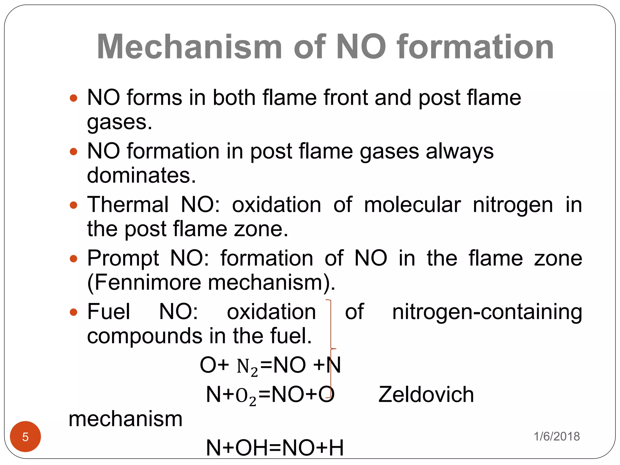
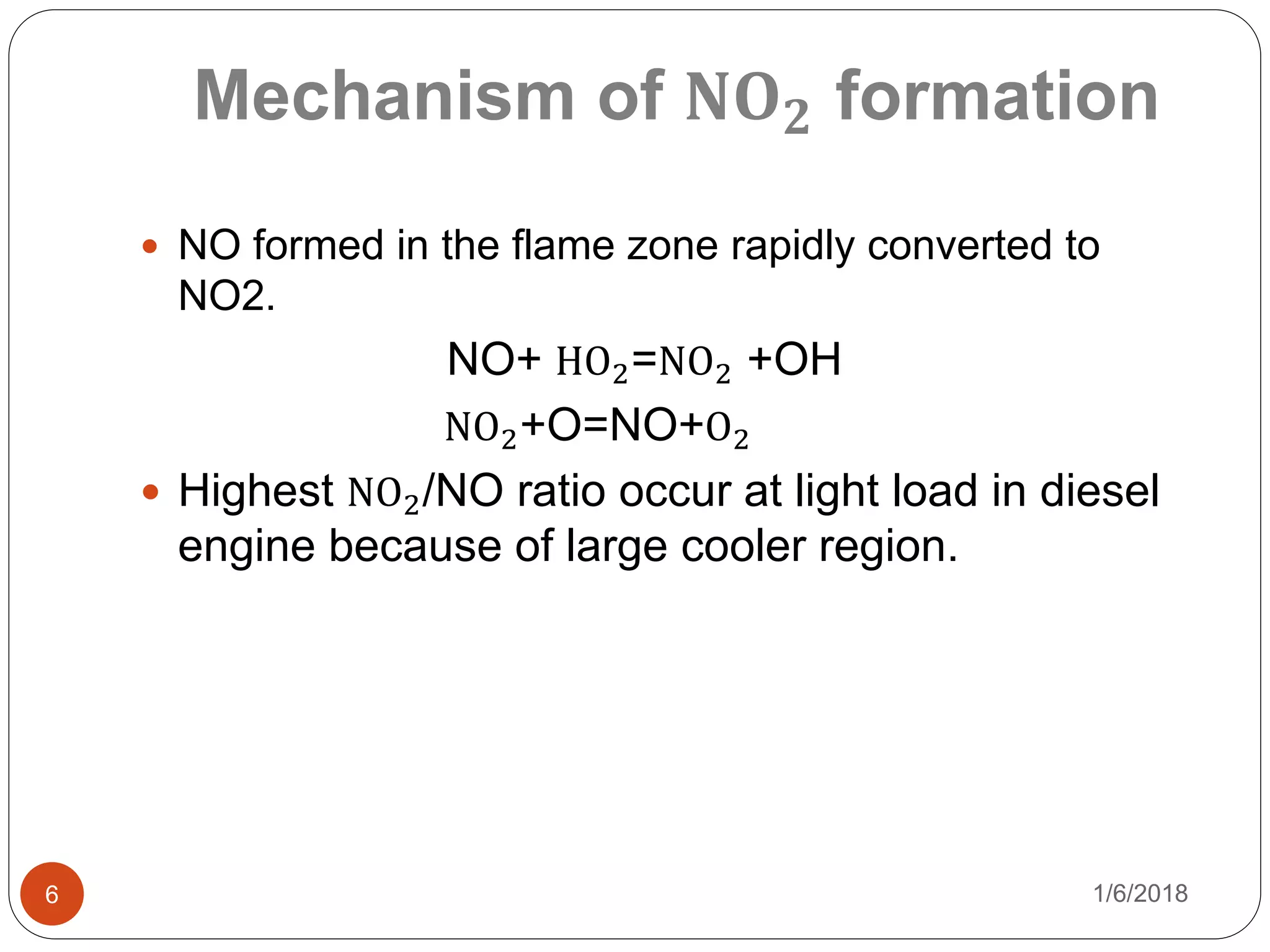
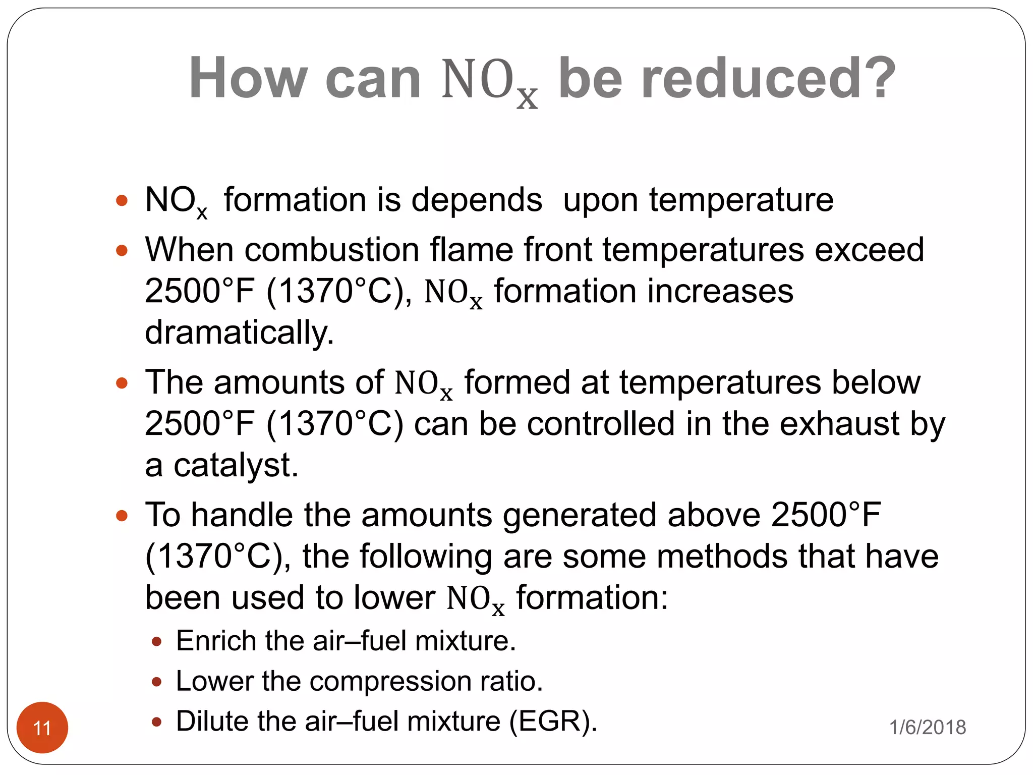
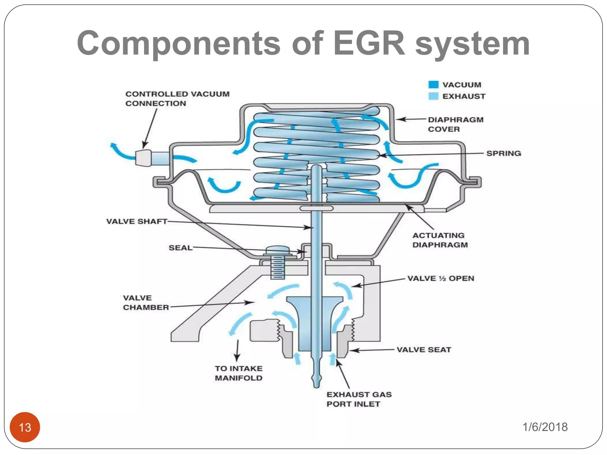
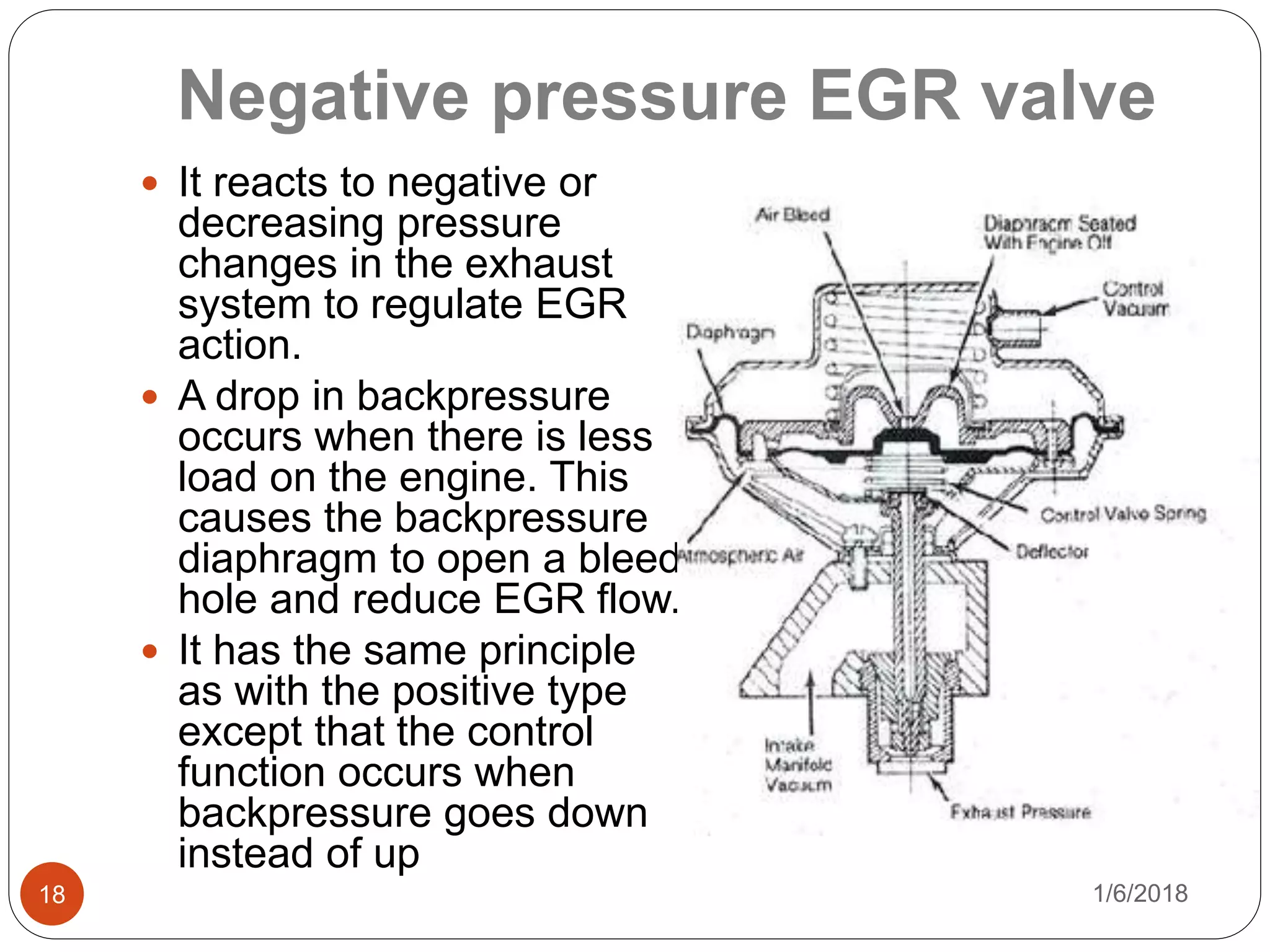
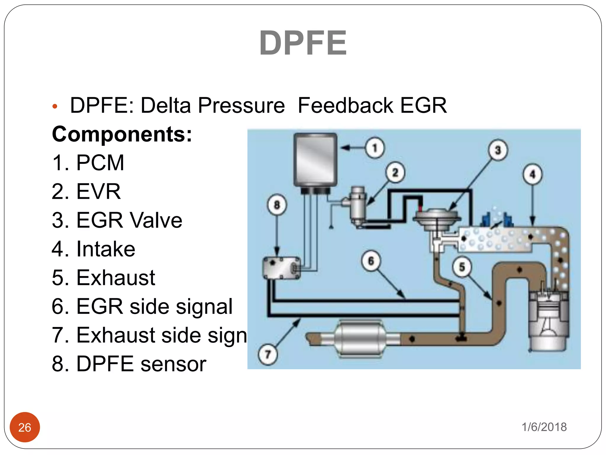
Muhammad Saqlain Haider 2011-ME-330
Exhaust gas recirculation and its
utilization in IC engines
1/6/20181
University Of Engineering & Technology Lahore,
KSK Campus.
1/6/20182
Contents
 Introduction.
 What are NOx?? .
 Mechanism of NO and NO2 formation.
 Factors affecting NO emissions.
 How can NOx be reduced?.
 Components of EGR system.
 Working of EGR system.
 EGR operation schedule.
 Types of EGR control valves.
 Advantages and disadvantages of EGR.
 EGR feed back system.
1/6/20184
What are 𝑁𝑂𝑥?
 Nitrogen N2 and oxygen O2 molecules are
separated into individual atoms of nitrogen and
oxygen during the combustion process.
 Formation of NO and NO2.
 NO and NO2 collectively known as NOx.
 NO is the predominant oxide of nitrogen
produced inside the engine cylinder.
 Diesel engines contain comparable amount of
nitrogen then petrol engines.
Mechanism of NO formation
1/6/20185
 NO forms in both flame front and post flame
gases.
 NO formation in post flame gases always
dominates.
 Thermal NO: oxidation of molecular nitrogen in
the post flame zone.
 Prompt NO: formation of NO in the flame zone
(Fennimore mechanism).
 Fuel NO: oxidation of nitrogen-containing
compounds in the fuel.
O+ N2=NO +N
N+O2=NO+O Zeldovich
mechanism
N+OH=NO+H
Mechanism of 𝐍𝐎 𝟐 formation
1/6/20186
 NO formed in the flame zone rapidly converted to
NO2.
NO+ HO2=NO2 +OH
NO2+O=NO+O2
 Highest NO2/NO ratio occur at light load in diesel
engine because of large cooler region.
Factor affecting NO emission
1/6/20187
 Fuel to air equivalence ratio
 Spark timing
 Burned gas fraction
 Residual gas fraction
 Recycled exhaust gas
 Change in time history of temperature
 Change in oxygen concentration
1/6/20188
NO formation with A/F
1/6/20189
NO variation with spark timing
1/6/201810
NO variation with % EGR
How can NOx be reduced?
1/6/201811
 NOx formation is depends upon temperature
 When combustion flame front temperatures exceed
2500°F (1370°C), NOx formation increases
dramatically.
 The amounts of NOx formed at temperatures below
2500°F (1370°C) can be controlled in the exhaust by
a catalyst.
 To handle the amounts generated above 2500°F
(1370°C), the following are some methods that have
been used to lower NOx formation:
 Enrich the air–fuel mixture.
 Lower the compression ratio.
 Dilute the air–fuel mixture (EGR).
NO vs temperature and ф
1/6/201812
 High temperature and High oxygen
concentrations result in high NO formation rate.
1/6/201813
Components of EGR system
1/6/201814
Working of EGR
1/6/201815
EGR operating conditions
Ported EGR valve
1/6/201816
Consists of
 Vacuum diaphragm
 Stem control valve
 Small pipe from the exhaust
manifold or an internal
crossover passage in the
cylinder head
 Parted vacuum switch or a
computer-controlled
solenoid
Positive pressure EGR valve
1/6/201817
 It use exhaust
backpressure to vary the
point at which they open
and their flow rates.
 Inside the valve there is
a second diaphragm that
reacts to backpressure in
the exhaust system.
 Second diaphragm opens
and closes bleed hole
which control main EGR
vacuum.
Negative pressure EGR valve
1/6/201818
 It reacts to negative or
decreasing pressure
changes in the exhaust
system to regulate EGR
action.
 A drop in backpressure
occurs when there is less
load on the engine. This
causes the backpressure
diaphragm to open a bleed
hole and reduce EGR flow.
 It has the same principle
as with the positive type
except that the control
function occurs when
backpressure goes down
instead of up
Pulse width modulated EGR
valve
1/6/201819
 Powertrain control module (PCM) cycles the EGR
vacuum control solenoid rapidly on and off.
 The computer controls the flow rate by sending
electrical signals to a solenoid vacuum valve
between the PCM and the EGR valve.
 The amount of "on" time versus "off" time for the
EGR solenoid ranges from 0 to 100 percent, and
the average amount of "on" time versus "off" time
at any given instant determines how much EGR
flow occurs.
Digital electronic EGR valve
1/6/201820
 This type of valve
also uses vacuum to
open the valve but
regulates EGR flow
according to
computer control.
 It has three metering
orifices that are
opened and closed
by solenoids.
 To match EGR to the
engine's
requirements various
combinations of these
three solenoids can
be achieved.
Linear controlled EGR valve
1/6/201821
 It is electrically operated
and uses a small
computer-controlled
stepper motor to open and
close the EGR valve
instead of vacuum.
 It has a control solenoid
and EGR valve position
(EVP) sensor. The sensor
works on the same
principle as a throttle
position sensor. voltage
signal ranges from 0.3
volts to 5.0 volts.
 The PCM controls EGR
flow by pulsing the signal
to the EGR solenoid.
 Reduced NOx
 Improved engine life through reduced cylinder
temperatures (particularly exhaust valve life)
 The exhaust gas, added to the fuel, oxygen, and
combustion products, increases the specific heat
capacity of the cylinder contents, which lowers the
adiabatic flame temperature.
 Reduced throttling losses in SI engine.
 Reduced heat rejection.
 Reduced chemical dissociation.
1/6/201822
Advantages of EGR
 It reduces the available oxygen in the cylinder.
 Reduce the peak power available from the engine.
 The EGR valve can not respond instantly to
changes in demand.
 Can not achieve perfect mixing in each cylinder.
 Combustion contamination.
 Control system stability.
 Materials and durability
1/6/201823
Disadvantages of EGR
The PCM needs to know when and how much EGR
flow is present when commanded and not
commanded. It have sensing systems called
Feedback, which is simply some sensor used to
determine presence of flow and amount.
Types:
 PFE
 DPFE
 EVP
1/6/201824
EGR Feed back
• PFE: Pressure Feedback EGR
Components:
1. PCM
2. EVR
3. EGR Valve
4. Intake
5. Exhaust
6. EGR pressure
measurement
7. PFE sensor
1/6/201825
PFE
• DPFE: Delta Pressure Feedback EGR
Components:
1. PCM
2. EVR
3. EGR Valve
4. Intake
5. Exhaust
6. EGR side signal
7. Exhaust side signal
8. DPFE sensor
1/6/201826
DPFE
EVP: EGR Valve Position
Components:
1.PCM
2.EVR
3.EVP
4.Intake
5.Exhaust
1/6/201827
EVP
Thank You
1/6/2018

Exhaust gas Re circulation Systems

  • 1.
    Muhammad Saqlain Haider2011-ME-330 Exhaust gas recirculation and its utilization in IC engines 1/6/20181 University Of Engineering & Technology Lahore, KSK Campus.
  • 2.
    1/6/20182 Contents  Introduction.  Whatare NOx?? .  Mechanism of NO and NO2 formation.  Factors affecting NO emissions.  How can NOx be reduced?.  Components of EGR system.  Working of EGR system.  EGR operation schedule.  Types of EGR control valves.  Advantages and disadvantages of EGR.  EGR feed back system.
  • 3.
    1/6/20184 What are 𝑁𝑂𝑥? Nitrogen N2 and oxygen O2 molecules are separated into individual atoms of nitrogen and oxygen during the combustion process.  Formation of NO and NO2.  NO and NO2 collectively known as NOx.  NO is the predominant oxide of nitrogen produced inside the engine cylinder.  Diesel engines contain comparable amount of nitrogen then petrol engines.
  • 4.
    Mechanism of NOformation 1/6/20185  NO forms in both flame front and post flame gases.  NO formation in post flame gases always dominates.  Thermal NO: oxidation of molecular nitrogen in the post flame zone.  Prompt NO: formation of NO in the flame zone (Fennimore mechanism).  Fuel NO: oxidation of nitrogen-containing compounds in the fuel. O+ N2=NO +N N+O2=NO+O Zeldovich mechanism N+OH=NO+H
  • 5.
    Mechanism of 𝐍𝐎𝟐 formation 1/6/20186  NO formed in the flame zone rapidly converted to NO2. NO+ HO2=NO2 +OH NO2+O=NO+O2  Highest NO2/NO ratio occur at light load in diesel engine because of large cooler region.
  • 6.
    Factor affecting NOemission 1/6/20187  Fuel to air equivalence ratio  Spark timing  Burned gas fraction  Residual gas fraction  Recycled exhaust gas  Change in time history of temperature  Change in oxygen concentration
  • 7.
  • 8.
  • 9.
  • 10.
    How can NOxbe reduced? 1/6/201811  NOx formation is depends upon temperature  When combustion flame front temperatures exceed 2500°F (1370°C), NOx formation increases dramatically.  The amounts of NOx formed at temperatures below 2500°F (1370°C) can be controlled in the exhaust by a catalyst.  To handle the amounts generated above 2500°F (1370°C), the following are some methods that have been used to lower NOx formation:  Enrich the air–fuel mixture.  Lower the compression ratio.  Dilute the air–fuel mixture (EGR).
  • 11.
    NO vs temperatureand ф 1/6/201812  High temperature and High oxygen concentrations result in high NO formation rate.
  • 12.
  • 13.
  • 14.
  • 15.
    Ported EGR valve 1/6/201816 Consistsof  Vacuum diaphragm  Stem control valve  Small pipe from the exhaust manifold or an internal crossover passage in the cylinder head  Parted vacuum switch or a computer-controlled solenoid
  • 16.
    Positive pressure EGRvalve 1/6/201817  It use exhaust backpressure to vary the point at which they open and their flow rates.  Inside the valve there is a second diaphragm that reacts to backpressure in the exhaust system.  Second diaphragm opens and closes bleed hole which control main EGR vacuum.
  • 17.
    Negative pressure EGRvalve 1/6/201818  It reacts to negative or decreasing pressure changes in the exhaust system to regulate EGR action.  A drop in backpressure occurs when there is less load on the engine. This causes the backpressure diaphragm to open a bleed hole and reduce EGR flow.  It has the same principle as with the positive type except that the control function occurs when backpressure goes down instead of up
  • 18.
    Pulse width modulatedEGR valve 1/6/201819  Powertrain control module (PCM) cycles the EGR vacuum control solenoid rapidly on and off.  The computer controls the flow rate by sending electrical signals to a solenoid vacuum valve between the PCM and the EGR valve.  The amount of "on" time versus "off" time for the EGR solenoid ranges from 0 to 100 percent, and the average amount of "on" time versus "off" time at any given instant determines how much EGR flow occurs.
  • 19.
    Digital electronic EGRvalve 1/6/201820  This type of valve also uses vacuum to open the valve but regulates EGR flow according to computer control.  It has three metering orifices that are opened and closed by solenoids.  To match EGR to the engine's requirements various combinations of these three solenoids can be achieved.
  • 20.
    Linear controlled EGRvalve 1/6/201821  It is electrically operated and uses a small computer-controlled stepper motor to open and close the EGR valve instead of vacuum.  It has a control solenoid and EGR valve position (EVP) sensor. The sensor works on the same principle as a throttle position sensor. voltage signal ranges from 0.3 volts to 5.0 volts.  The PCM controls EGR flow by pulsing the signal to the EGR solenoid.
  • 21.
     Reduced NOx Improved engine life through reduced cylinder temperatures (particularly exhaust valve life)  The exhaust gas, added to the fuel, oxygen, and combustion products, increases the specific heat capacity of the cylinder contents, which lowers the adiabatic flame temperature.  Reduced throttling losses in SI engine.  Reduced heat rejection.  Reduced chemical dissociation. 1/6/201822 Advantages of EGR
  • 22.
     It reducesthe available oxygen in the cylinder.  Reduce the peak power available from the engine.  The EGR valve can not respond instantly to changes in demand.  Can not achieve perfect mixing in each cylinder.  Combustion contamination.  Control system stability.  Materials and durability 1/6/201823 Disadvantages of EGR
  • 23.
    The PCM needsto know when and how much EGR flow is present when commanded and not commanded. It have sensing systems called Feedback, which is simply some sensor used to determine presence of flow and amount. Types:  PFE  DPFE  EVP 1/6/201824 EGR Feed back
  • 24.
    • PFE: PressureFeedback EGR Components: 1. PCM 2. EVR 3. EGR Valve 4. Intake 5. Exhaust 6. EGR pressure measurement 7. PFE sensor 1/6/201825 PFE
  • 25.
    • DPFE: DeltaPressure Feedback EGR Components: 1. PCM 2. EVR 3. EGR Valve 4. Intake 5. Exhaust 6. EGR side signal 7. Exhaust side signal 8. DPFE sensor 1/6/201826 DPFE
  • 26.
    EVP: EGR ValvePosition Components: 1.PCM 2.EVR 3.EVP 4.Intake 5.Exhaust 1/6/201827 EVP
  • 27.

Editor's Notes

  • #6 In most practical combustion devices the thermal NO is the main source The contribution of reaction 3 is small for lean mixtures, but for rich mixtures it should be considered. Forward reaction 1 controls the system, but it is slow at low temperatures (high activation energy). Thus it is effective in post-flame zone where temperature is high and the time is available.
  • #15 This causes a correspondingly lower heat release and peak cylinder temperature, and reduces the formation of NOx.
  • #16 At idle, the throttle plate in the carburetor or fuel injection throttle body is closed. This blocks off engine vacuum so it can’t act on the EGR valve. The EGR spring holds the valve shut and exhaust gases do NOT enter the intake manifold. When the throttle plate is swung open to increase speed, engine vacuum is applied to the EGR hose. Vacuum pulls the EGR diaphragm up. In turn, the diaphragm pulls the valve open. At higher engine speeds, there is enough air flowing into the engine that the air-fuel mixture is not upset by the open EGR valve.
  • #17 The typical ported vacuum EGR valve consists of a vacuum diaphragm connected to a poppet or tapered stem flow control valve. The EGR valve itself is usually mounted either on a spacer under the carburetor or on the intake manifold. A small pipe from the exhaust manifold or an internal crossover passage in the cylinder head and intake manifold routes exhaust to the valve. When vacuum is applied to the EGR valve, it opens. This allows intake vacuum to suck exhaust into the engine. To prevent the EGR valve from opening when the engine is cold, the vacuum line to the EGR valve may be connected to a parted vacuum switch or a computer-controlled solenoid. Vacuum is not allowed to pass to the valve until the engine is warm. EGR isn't needed when the engine is cold, only when it is warm and under load
  • #18 The diaphragm opens and closes a small bleed hole in the main EGR vacuum circuit or diaphragm chamber. Opening the bleed hole reduces vacuum to the main diaphragm and prevents the valve from opening fully. Closing the bleed hole allows full vacuum to reach the main diaphragm so the valve can open wide and allow maximum EGR flow. With positive backpressure EGR valves, any increase in exhaust backpressure causes the EGR valve to open. This reduces backpressure somewhat, allowing the backpressure diaphragm to bleed off some control vacuum. The EGR valve begins to close and exhaust pressure rises again. The EGR valve oscillates open and closed with changing exhaust pressure to maintain a sort of balanced flow
  • #20 The pulse-width modulated EGR system is controlled entirely by the powertrain control module (PCM). The computer controls the flow rate by sending electrical signals to a solenoid vacuum valve between the PCM and the EGR valve. The solenoid pulses up to 32 times per second. To determine the pulse width, the PCM relies on a ported vacuum signal.
  • #22 The advantage of this approach is that the EGR valve operates totally independent of engine vacuum. It can be opened in various increments depending on what the engine control module determines the engine needs at any given moment in time. This provides better regulation of EGR flow than with conventional vacuum controlled EGR valves.
  • #24 For this reason the EGR is usually shut off when full power is demanded, so the EGR approach to controlling NOx fails in this situation. the production of particulates (fuel which has only partially combusted) is increased when EGR is applied.
  • #25 For this reason the EGR is usually shut off when full power is demanded, so the EGR approach to controlling NOx fails in this situation. the production of particulates (fuel which has only partially combusted) is increased when EGR is applied.