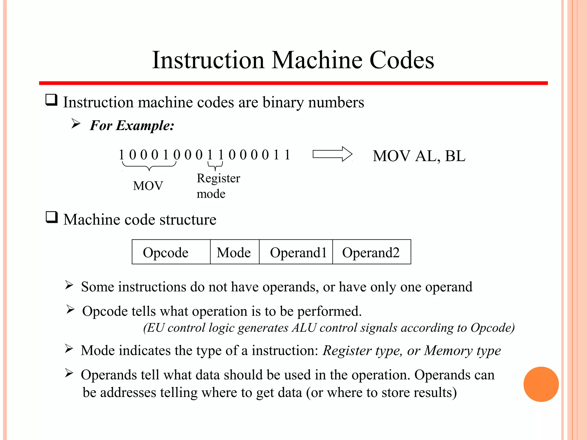
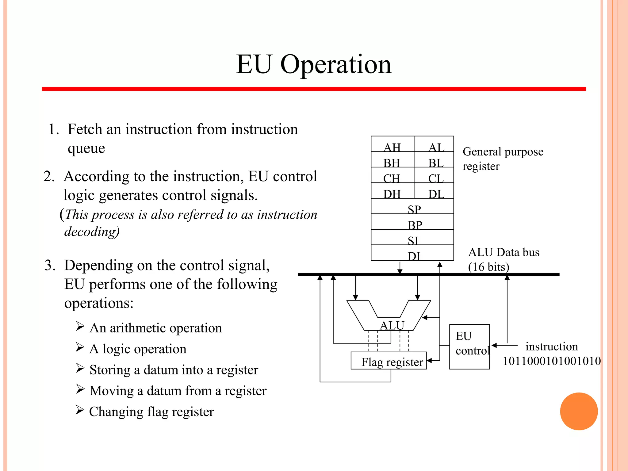
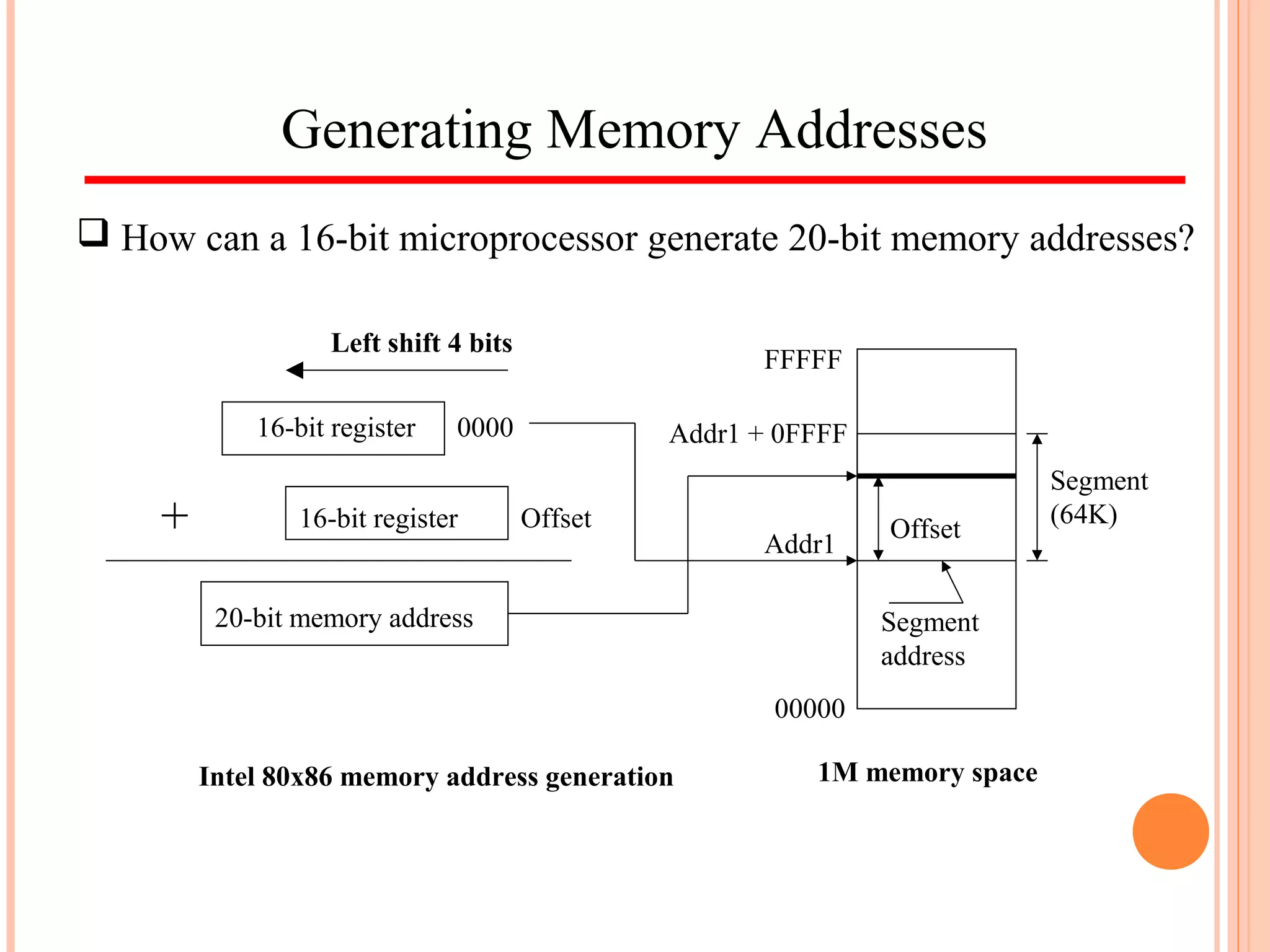
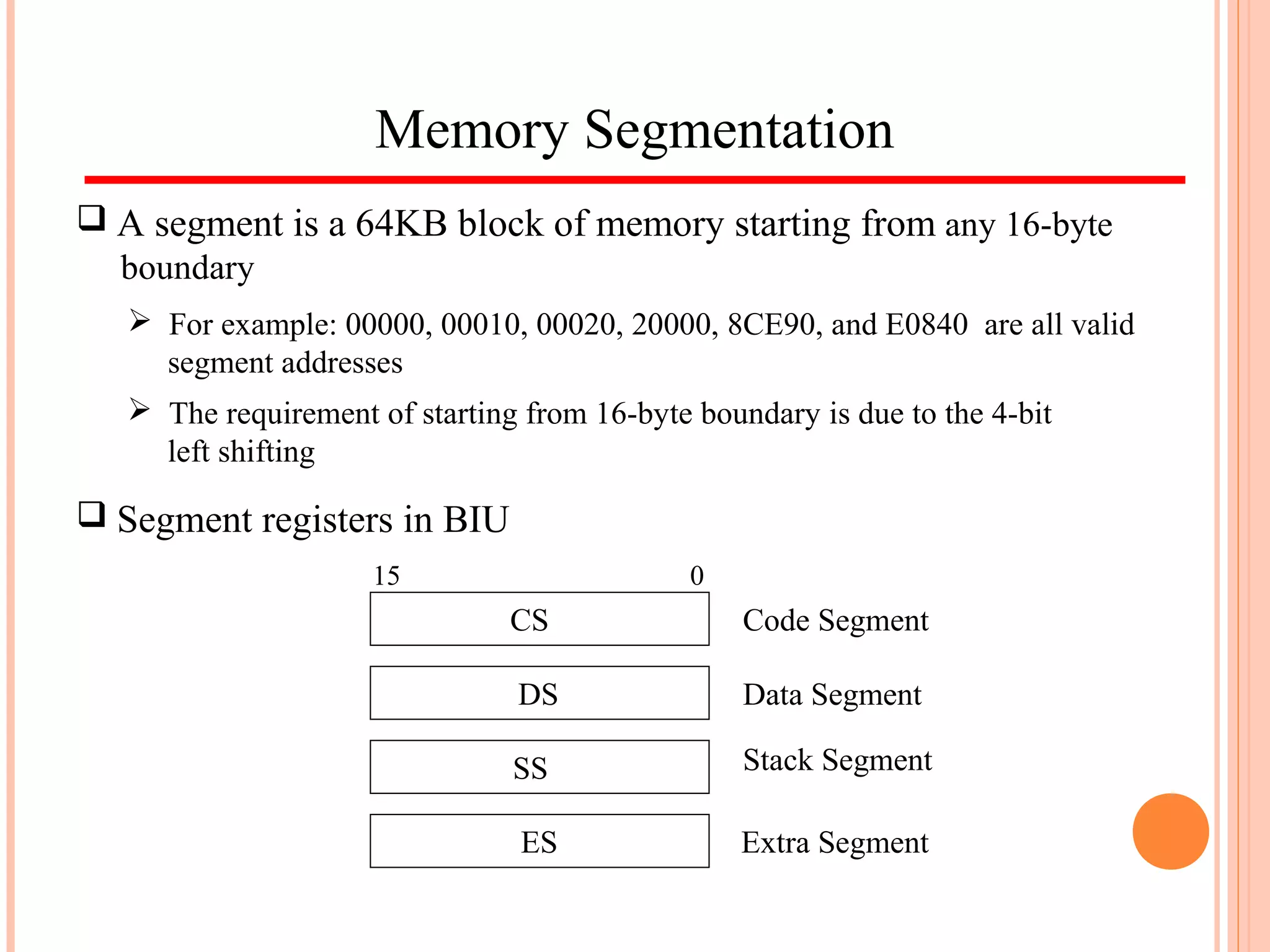
Downloaded 76 times
![Accessing Data Memory
There is a number of methods to generate the memory address when
accessing data memory. These methods are referred to as
Addressing Modes
Examples:
— Direct addressing: MOV AL, [0300H]
1 2 3 4 0
0 3 0 0
2 6 4 01
DS
Memory address
(assume DS=1234H)
— Register indirect addressing: MOV AL, [SI]
1 2 3 4 0
0 3 1 0
2 6 5 01
DS
Memory address
(assume DS=1234H)
(assume SI=0310H)](https://image.slidesharecdn.com/introductionto8086part1-140504025029-phpapp01/75/Introduction-to-intel-8086-part1-29-2048.jpg)

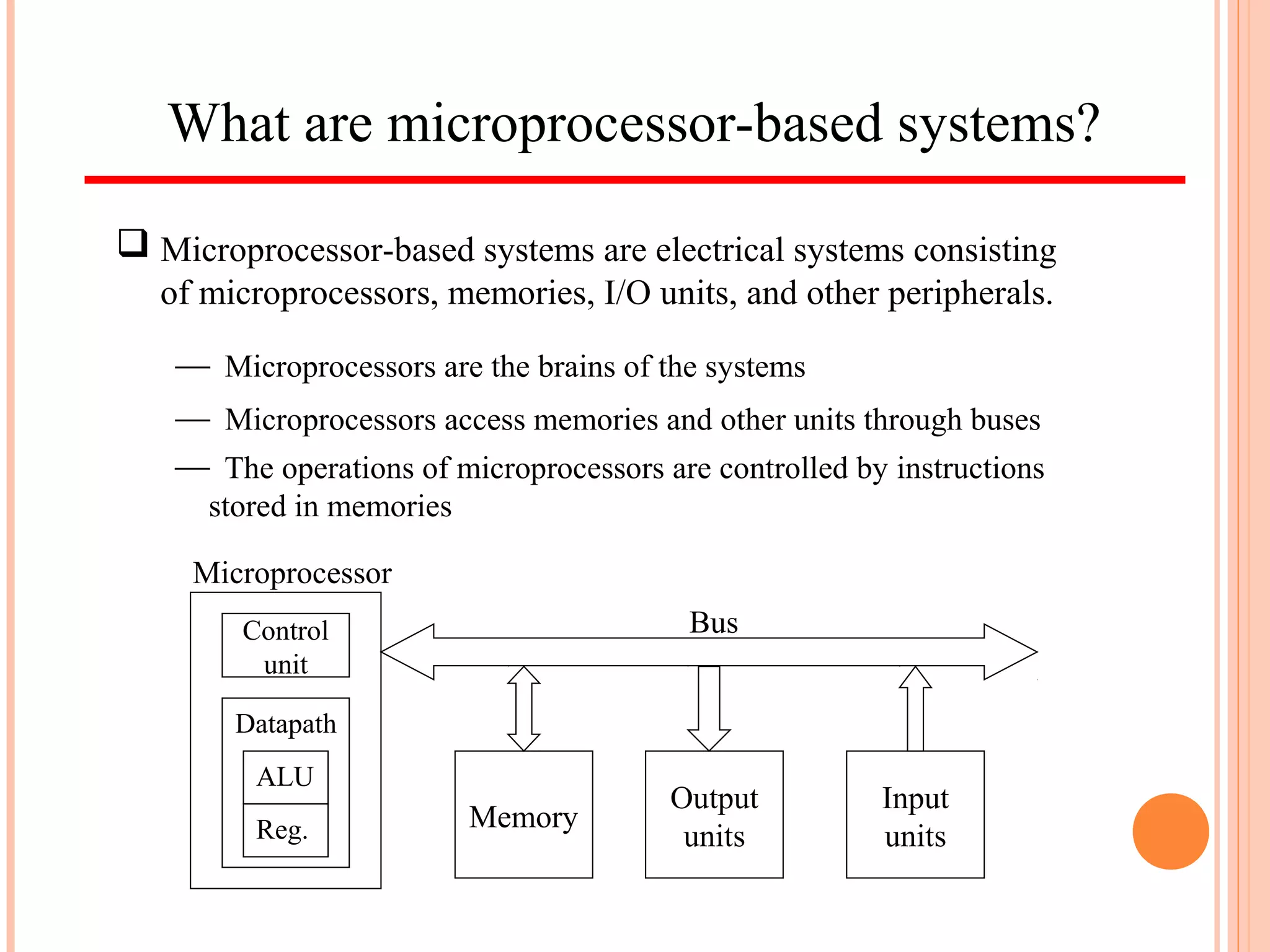
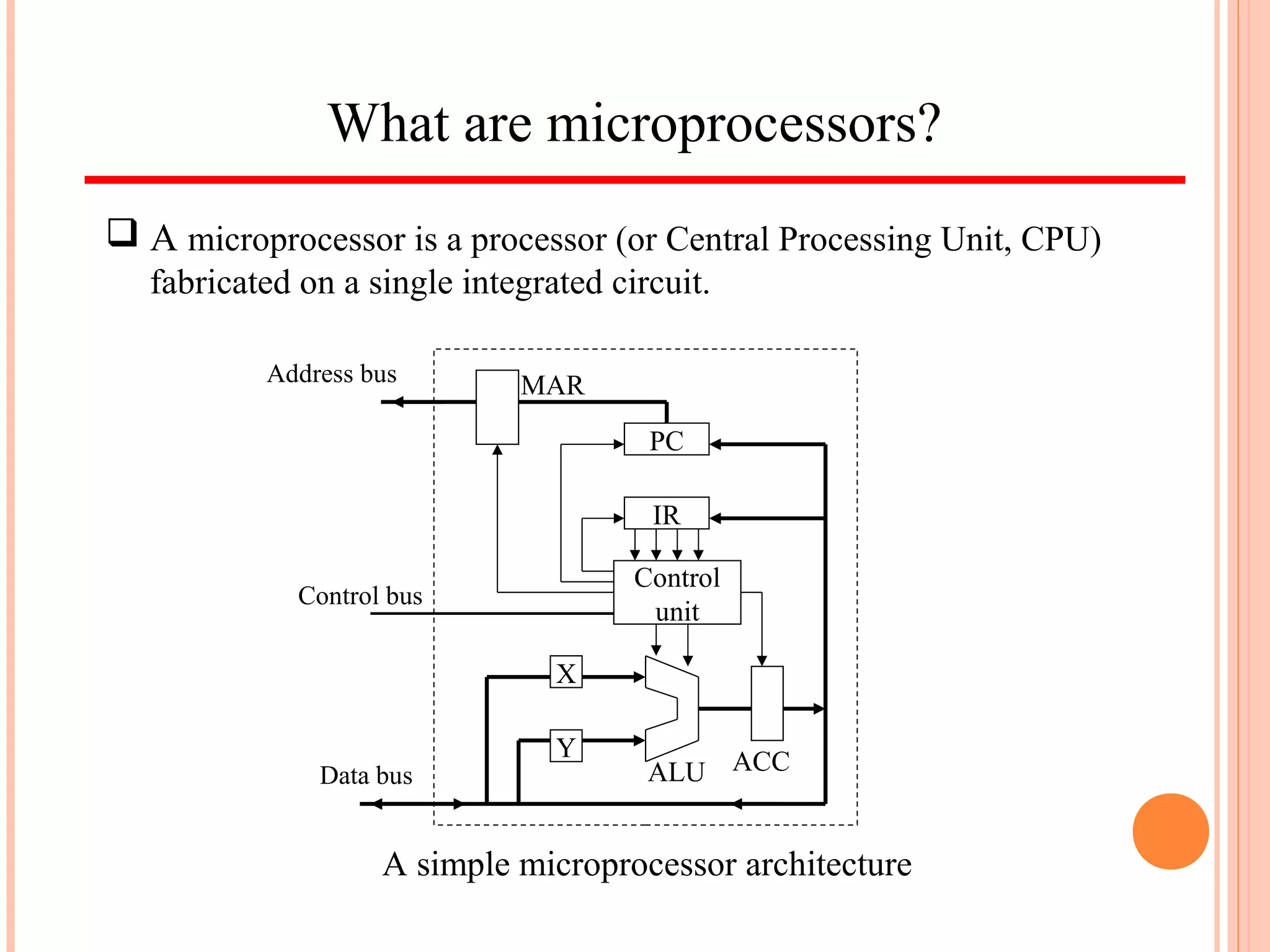
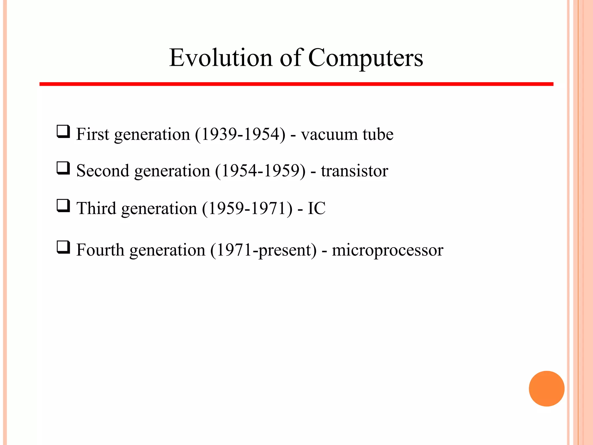
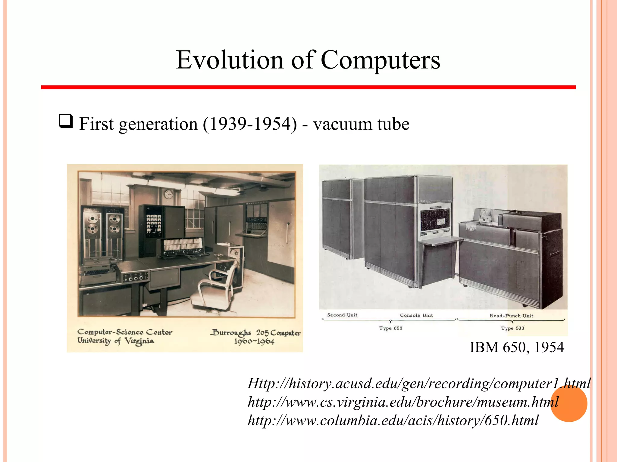
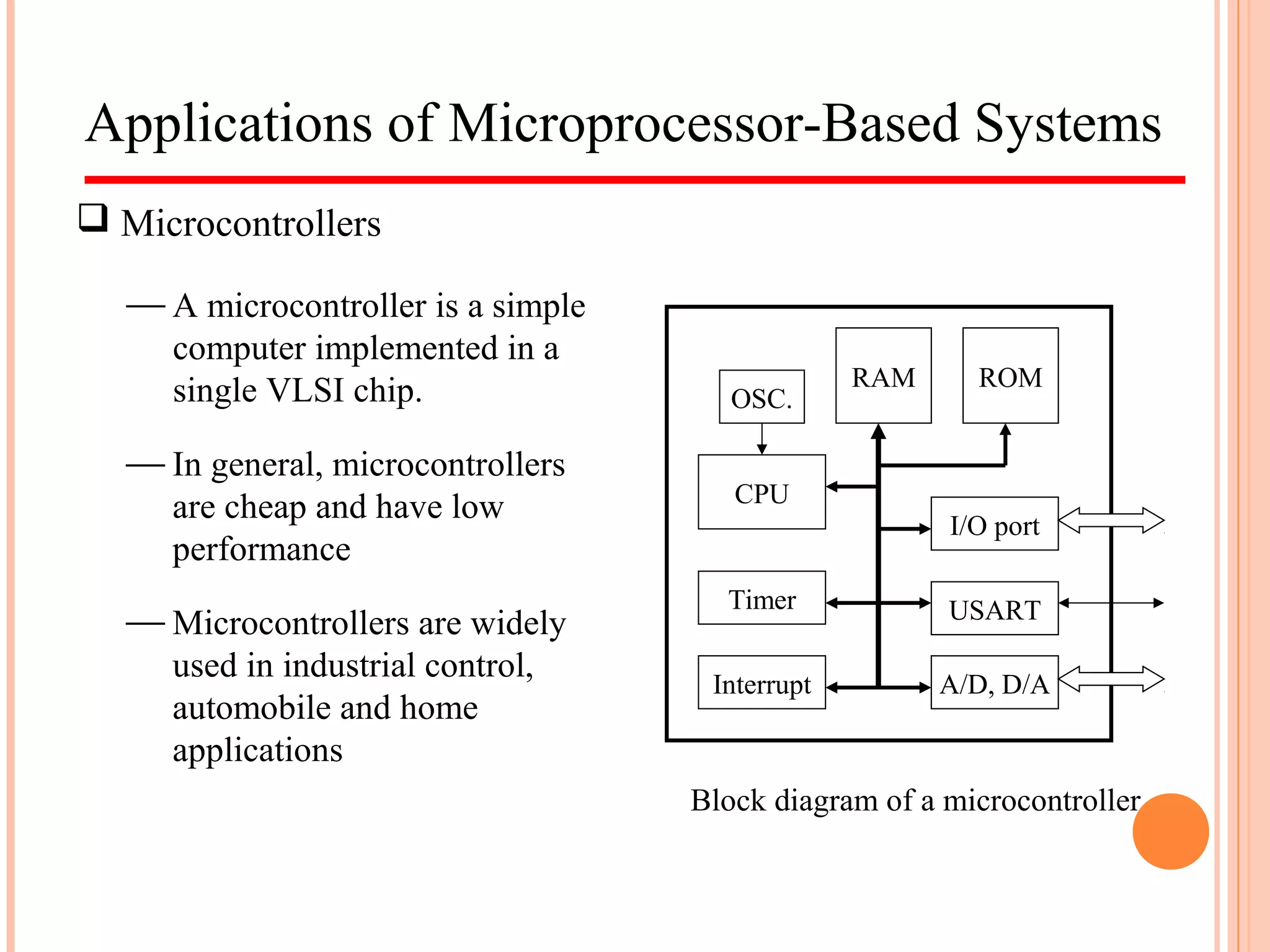
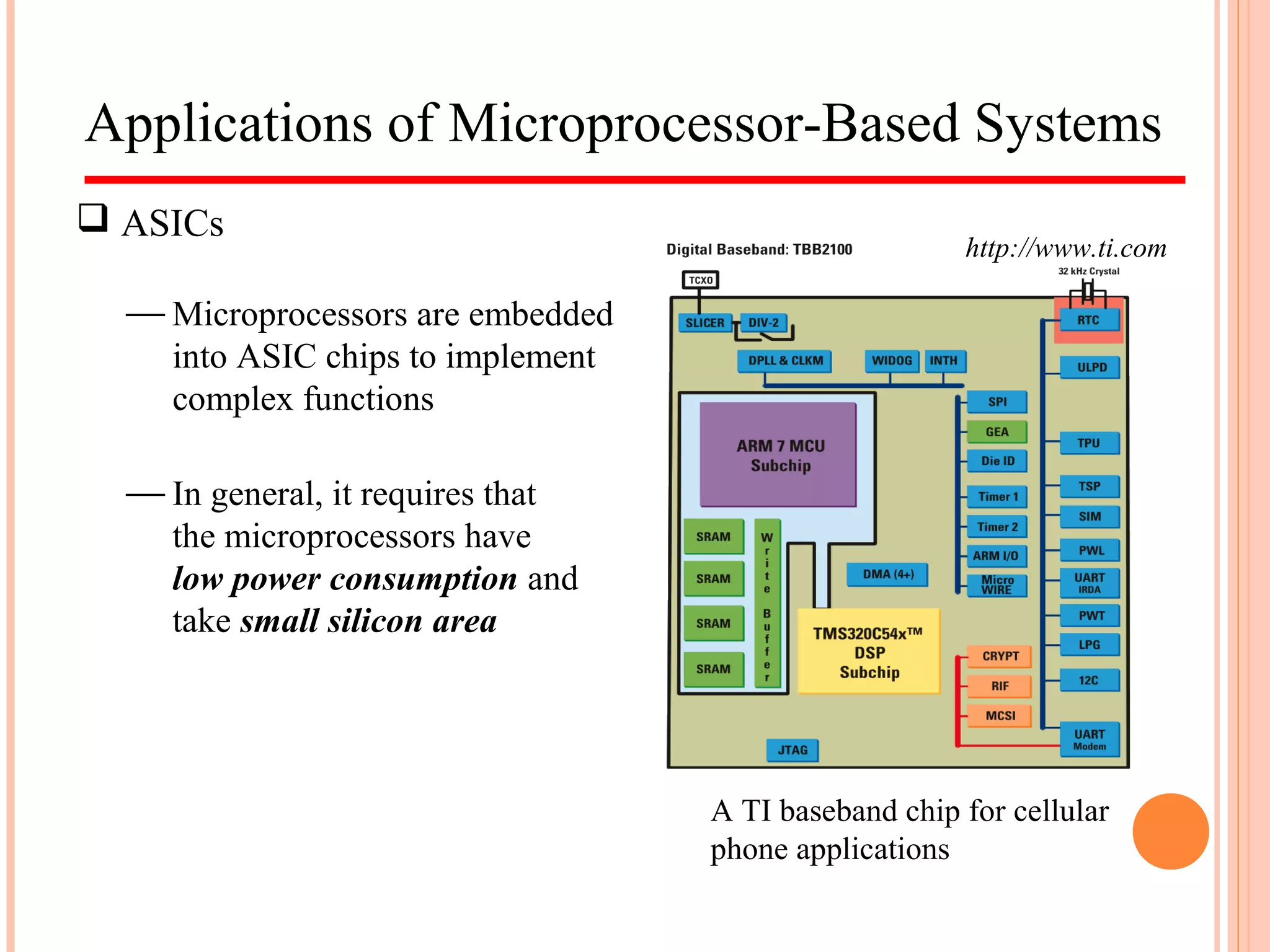
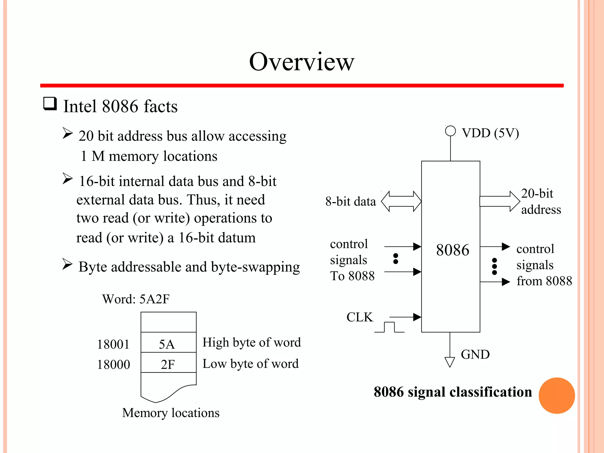
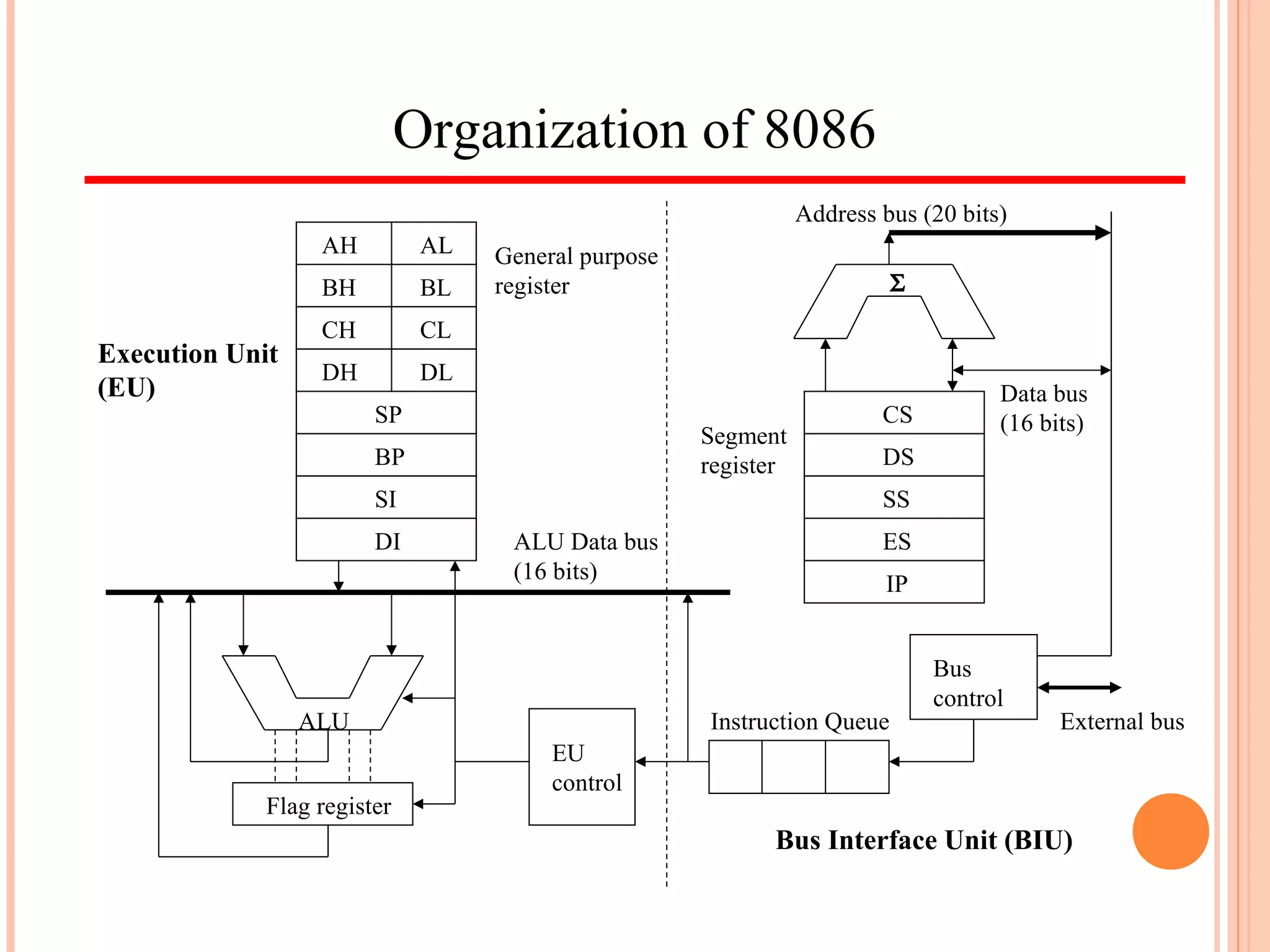
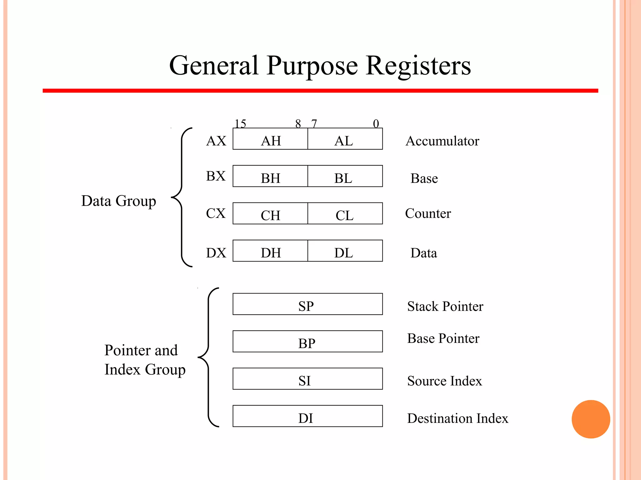
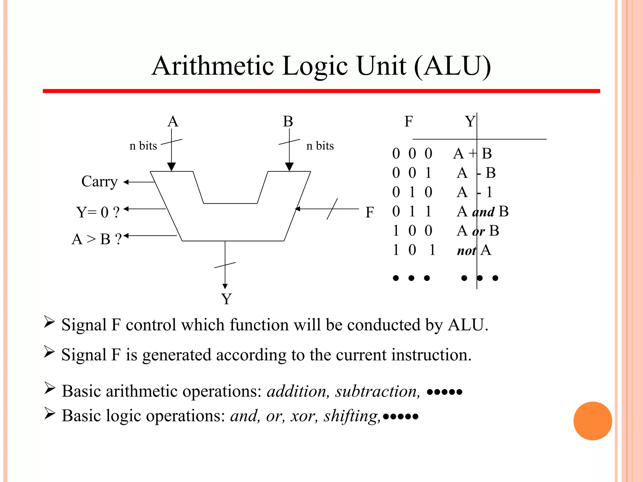
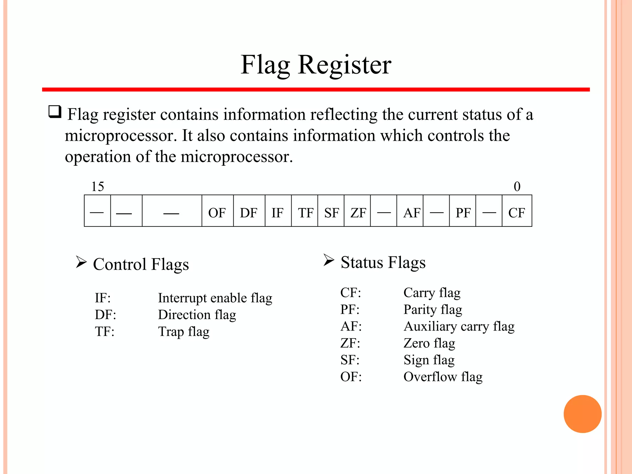
The document provides an overview of the Intel 8086 microprocessor. It discusses how microprocessor-based systems work and the evolution of computers from vacuum tubes to microprocessors. It then describes the architecture of the Intel 8086, including its registers, arithmetic logic unit, instruction set, addressing modes, memory segmentation, and interrupts. It also discusses the minimum and maximum operation modes of the 8086.