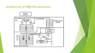
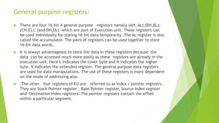
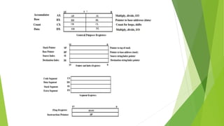
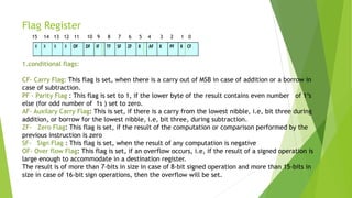
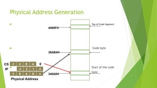
Chapter 2
The 8086 Microprocessor Architecture
Topics Covered
 Features of 8086
 Architecture of 8086
 Bus Interface Unit (BIU)
 Execution Unit (EU)
 Register Organization
 General purpose registers
 Segment registers
 Pointer and index registers
 Flag register
 Bus operation
 Memory Segmentation
8086 CPU Architecture :
 To improve the performance by implementing the parallel processing concept the
CPU of the 8086 /8088 is divided into two independent sections .
 They are :
 Bus Interface Unit (BIU)
 Execution Unit.(EU).
 The BIU sends out addresses ,fetches instructions ,read data from ports and
memory and writes data to ports and memory.i.e the BIU handles all transfers data
and addresses on the buses required by the execution Unit . Whereas the Execution
Unit decodes the instructions and executes the instructions.
Architecture of 8086 Microprocessor
The Execution Unit :
The Execution Unit consists of
 a control system ,
 a 16-bit ALU,
 16-bit Flag register and
 four general purpose registers(AX,BX,CX,DX),
 pointer registers (SP,BP) and Index registers(SI,DI) of each 16-bits .
The control circuitry controls the internal operations .
The decoder in the execution unit decodes the instructions fetched from the
memory into a series of actions.
The ALU can add ,subtract, perform operations like logical AND,OR,XOR,
increment, decrement, complement ,and shifting the binary numbers.
Bus Interface Unit :
 The BIU consists of a 6-byte long instruction register called Queue.
 And four stack segment registers (ES,CS,SS,DS) , one Instruction Pointer(IP) and an adder
circuit to calculate the 20bit physical address of a location.
 This bus interface unit will perform all the external bus operations. They are fetching the
instructions from the memory, read/write data from/into memory or port and also
supporting the instruction Queue etc.
 The BIU fetches up to six instruction bytes from the memory and stores these pre-fetched
bytes in a first –in first out register set called Queue. When the execution unit is ready for the
execution of the instruction ,instead of fetching the byte from the memory ,it reads the byte
from the Queue .
 This will increase the overall speed of microprocessor .Fetching the next instruction while the
current instruction executes is called pipelining or parallel processing.
REGISTER ORGANISATION :
 The 14 registers of 8086 microprocessor are categorized into four groups.
 They are general purpose data registers , Pointer & Index registers , Segment registers
and Flag register as shown in the table below.
S.No Type Register width Name of the Registers
1 General purpose Registers(4)
16-bit AX,BX,CX,DX
8-bit
AL,AH,BL,BH,CL,CH,DL,DH
2 Pointer Registers 16-bit
Stack Pointer(SP)
Base Pointer(BP)
3 Index Registers 16-bit
Source Index(SI)
Destination Index(DI)
4 Segment Registers
16-bit
Code Segment(CS)
Data Segment(DS)
Stack Segment(SS)
Extra Segment(ES)
5 Instruction 16-bit Instruction Pointer (IP)
6 Flag (PSW) 16-bit Flag Register
General purpose registers:
 There are four 16-bit 4 general purpose registers namely (AH, AL);(BH,BL);
(CH,CL); (and DH,DL) which are part of Execution unit. These registers can
be used individually for storing 16-bit data temporarily .The AL register is also
called the accumulator. The pairs of registers can be used together to store
16-bit data words.
 It is always advantageous to store the data in these registers because the
data can be accessed much more easily as these registers are already in the
execution unit. Here L indicates the lower byte and H indicates the higher
byte. X indicates the extended register. The general purpose data registers
are used for data manipulations. The use of these registers is more dependent
on the mode of addressing also.
 .The other four registers of EU are referred to as index / pointer registers.
They are Stack Pointer register , Base Pointer register, Source Index register
and Destination Index registers. The pointer registers contain the offset
within a particular segment.
 The BP & SP registers holds the offsets within the data and stack segments
respectively.
 The Index registers are used as general purpose registers as well as for
holding the offset in case of indexed based and relative indexed addressing
modes.
 The source Index register is generally used to store the offset of source data
in data segment while the Destination Index register used to store the offset
of destination in data or extra segment. These index registers are specifically
used in string manipulations.
Segment Registers :
 There are four 16-bit segment registers namely
 code segment register(CS),
 Stack segment register(SS),
 Data segment register(DS) and
 Extra segment register(ES).
 The code segment register is used for addressing the 64kB memory location in the code
segment of the memory ,where the code of the executable program is stored.
 Similarly the DS register points to the data segment of the 64kB memory where the data is
stored.
 The Extra segment register also refers to essentially another data segment of the memory
space.
 The SS register is useful for addressing stack segment of memory.
 So, the CS,DS,SS and ES segment registers respectively contains the segment addresses for
the code, data, stack and extra segments of the memory.
Instruction Pointer Register:
 It is a 16-bit register which always points to the next instruction to be
executed within the currently executing code segment.
 So, this register contains the 16-bit offset address pointing to the next
instruction code within the 64kB of the code segment area.
 Its content is automatically incremented as the execution of the next
instruction takes place.
Flag Register:
 This register is also called status register.
 It is a 16 bit register which contains six status flags and three control flags.
 So, only nine bits of the 16 bit register are defined and the remaining seven bits are
undefined.
 Normally this status flag bits indicate the status of the ALU after the arithmetic or logical
operations. Each bit of the status register is a flip/flop.
 The Flag register contains Carry flag, Parity flag, Auxiliary flag Zero flag, Sign flag ,Trap
flag, Interrupt flag, Direction flag and overflow flag as shown in the diagram.
 The CF,PF,AF,ZF,SF,OF are the status flags and the TF,IF and CF are the control flags.
Flag Register
X X X X OF DF IF TF SF ZF X AF X PF X CF
1.conditional flags:
CF- Carry Flag: This flag is set, when there is a carry out of MSB in case of addition or a borrow in
case of subtraction.
PF - Parity Flag : This flag is set to 1, if the lower byte of the result contains even number of 1’s
else (for odd number of 1s ) set to zero.
AF- Auxilary Carry Flag: This is set, if there is a carry from the lowest nibble, i.e, bit three during
addition, or borrow for the lowest nibble, i.e, bit three, during subtraction.
ZF- Zero Flag: This flag is set, if the result of the computation or comparison performed by the
previous instruction is zero
SF- Sign Flag : This flag is set, when the result of any computation is negative
OF- Over flow Flag: This flag is set, if an overflow occurs, i.e, if the result of a signed operation is
large enough to accommodate in a destination register.
The result is of more than 7-bits in size in case of 8-bit signed operation and more than 15-bits in
size in case of 16-bit sign operations, then the overflow will be set.
15 14 13 12 11 10 9 8 7 6 5 4 3 2 1 0
2.control flags
 TF - Tarp Flag: If this flag is set, the processor enters the single step execution mode.
 IF- Interrupt Flag: If this flag is set, the maskable interrupt INTR of 8086 is enabled and
if it is zero ,the interrupt is disabled. It can be set by using the STI instruction and can
be cleared by executing CLI instruction.
 DF- Direction Flag: This is used by string manipulation instructions. If this flag bit is ‘0’,
the string is processed beginning from the lowest address to the highest address, i.e.,
auto incrementing mode. Otherwise, the string is processed from the highest address
towards the lowest address, i.e., auto incrementing mode.
Segment Registers
 the 220
= 1M bytes of addresses are divided in to 4 64KB segments
 code segment - CS register stores upper 16 bits of its starting address
where executable program is stored
 stack segment - SS register stores upper 16 bits of its starting address
stores addresses and data while a subprogram is executed
 data segment - DS register stores upper 16 bits of its starting address
holds data
 extra segment - ES register stores upper 16 bits of its starting address
holds more data
Advantages of Memory Segmentation
 Allow the memory capacity to be 1MB even though the addresses associated
with the individual instructions are only 16 bits wide.
 Facilitate the use of separate memory areas for the program, its data and the
stack.
 Permit a program and/or its data to be put into different areas of memory
each time the program is executed.
 Multitasking becomes easy.
Instruction Pointer(IP)
 contains the 16-bit address of the next code byte in the code segment
 this is called an offset…it must be added to the address contained in the CS
register, which is called the base
 example:
 CS contains the value 348AH
 IP contains the value 4214H
 what’s the physical address of the next code byte?
 you can represent an address in segment base:offset form…348A:4214
Physical Address Generation
 Top of Code Segment
 Code byte
 Start of the code
 byte
348A0H
38AB4H
4489FH
4 2 1 4
3 8 A B 4
3 4 8 A 0CS
IP
Physical Address
 Segments and associated pointers:
Sl.No Segment Segment Registers pointers
1 Code segment CS IP
2 Data segment DS SI,DI,BX
3 Extra segment ES SI,DI
4 Stack segment SS SP,BP
Problems on physical address calculations
 1. calculate the physical address for the following :
 A) DS=2000H ,SI=2012H,ES=3000H

Chapter 2

  • 1.
    Chapter 2 The 8086Microprocessor Architecture
  • 2.
    Topics Covered  Featuresof 8086  Architecture of 8086  Bus Interface Unit (BIU)  Execution Unit (EU)  Register Organization  General purpose registers  Segment registers  Pointer and index registers  Flag register  Bus operation  Memory Segmentation
  • 3.
    8086 CPU Architecture:  To improve the performance by implementing the parallel processing concept the CPU of the 8086 /8088 is divided into two independent sections .  They are :  Bus Interface Unit (BIU)  Execution Unit.(EU).  The BIU sends out addresses ,fetches instructions ,read data from ports and memory and writes data to ports and memory.i.e the BIU handles all transfers data and addresses on the buses required by the execution Unit . Whereas the Execution Unit decodes the instructions and executes the instructions.
  • 4.
    Architecture of 8086Microprocessor
  • 5.
    The Execution Unit: The Execution Unit consists of  a control system ,  a 16-bit ALU,  16-bit Flag register and  four general purpose registers(AX,BX,CX,DX),  pointer registers (SP,BP) and Index registers(SI,DI) of each 16-bits . The control circuitry controls the internal operations . The decoder in the execution unit decodes the instructions fetched from the memory into a series of actions. The ALU can add ,subtract, perform operations like logical AND,OR,XOR, increment, decrement, complement ,and shifting the binary numbers.
  • 6.
    Bus Interface Unit:  The BIU consists of a 6-byte long instruction register called Queue.  And four stack segment registers (ES,CS,SS,DS) , one Instruction Pointer(IP) and an adder circuit to calculate the 20bit physical address of a location.  This bus interface unit will perform all the external bus operations. They are fetching the instructions from the memory, read/write data from/into memory or port and also supporting the instruction Queue etc.  The BIU fetches up to six instruction bytes from the memory and stores these pre-fetched bytes in a first –in first out register set called Queue. When the execution unit is ready for the execution of the instruction ,instead of fetching the byte from the memory ,it reads the byte from the Queue .  This will increase the overall speed of microprocessor .Fetching the next instruction while the current instruction executes is called pipelining or parallel processing.
  • 7.
    REGISTER ORGANISATION : The 14 registers of 8086 microprocessor are categorized into four groups.  They are general purpose data registers , Pointer & Index registers , Segment registers and Flag register as shown in the table below. S.No Type Register width Name of the Registers 1 General purpose Registers(4) 16-bit AX,BX,CX,DX 8-bit AL,AH,BL,BH,CL,CH,DL,DH 2 Pointer Registers 16-bit Stack Pointer(SP) Base Pointer(BP) 3 Index Registers 16-bit Source Index(SI) Destination Index(DI) 4 Segment Registers 16-bit Code Segment(CS) Data Segment(DS) Stack Segment(SS) Extra Segment(ES) 5 Instruction 16-bit Instruction Pointer (IP) 6 Flag (PSW) 16-bit Flag Register
  • 8.
    General purpose registers: There are four 16-bit 4 general purpose registers namely (AH, AL);(BH,BL); (CH,CL); (and DH,DL) which are part of Execution unit. These registers can be used individually for storing 16-bit data temporarily .The AL register is also called the accumulator. The pairs of registers can be used together to store 16-bit data words.  It is always advantageous to store the data in these registers because the data can be accessed much more easily as these registers are already in the execution unit. Here L indicates the lower byte and H indicates the higher byte. X indicates the extended register. The general purpose data registers are used for data manipulations. The use of these registers is more dependent on the mode of addressing also.  .The other four registers of EU are referred to as index / pointer registers. They are Stack Pointer register , Base Pointer register, Source Index register and Destination Index registers. The pointer registers contain the offset within a particular segment.
  • 10.
     The BP& SP registers holds the offsets within the data and stack segments respectively.  The Index registers are used as general purpose registers as well as for holding the offset in case of indexed based and relative indexed addressing modes.  The source Index register is generally used to store the offset of source data in data segment while the Destination Index register used to store the offset of destination in data or extra segment. These index registers are specifically used in string manipulations.
  • 11.
    Segment Registers : There are four 16-bit segment registers namely  code segment register(CS),  Stack segment register(SS),  Data segment register(DS) and  Extra segment register(ES).  The code segment register is used for addressing the 64kB memory location in the code segment of the memory ,where the code of the executable program is stored.  Similarly the DS register points to the data segment of the 64kB memory where the data is stored.  The Extra segment register also refers to essentially another data segment of the memory space.  The SS register is useful for addressing stack segment of memory.  So, the CS,DS,SS and ES segment registers respectively contains the segment addresses for the code, data, stack and extra segments of the memory.
  • 12.
    Instruction Pointer Register: It is a 16-bit register which always points to the next instruction to be executed within the currently executing code segment.  So, this register contains the 16-bit offset address pointing to the next instruction code within the 64kB of the code segment area.  Its content is automatically incremented as the execution of the next instruction takes place. Flag Register:  This register is also called status register.  It is a 16 bit register which contains six status flags and three control flags.  So, only nine bits of the 16 bit register are defined and the remaining seven bits are undefined.  Normally this status flag bits indicate the status of the ALU after the arithmetic or logical operations. Each bit of the status register is a flip/flop.  The Flag register contains Carry flag, Parity flag, Auxiliary flag Zero flag, Sign flag ,Trap flag, Interrupt flag, Direction flag and overflow flag as shown in the diagram.  The CF,PF,AF,ZF,SF,OF are the status flags and the TF,IF and CF are the control flags.
  • 13.
    Flag Register X XX X OF DF IF TF SF ZF X AF X PF X CF 1.conditional flags: CF- Carry Flag: This flag is set, when there is a carry out of MSB in case of addition or a borrow in case of subtraction. PF - Parity Flag : This flag is set to 1, if the lower byte of the result contains even number of 1’s else (for odd number of 1s ) set to zero. AF- Auxilary Carry Flag: This is set, if there is a carry from the lowest nibble, i.e, bit three during addition, or borrow for the lowest nibble, i.e, bit three, during subtraction. ZF- Zero Flag: This flag is set, if the result of the computation or comparison performed by the previous instruction is zero SF- Sign Flag : This flag is set, when the result of any computation is negative OF- Over flow Flag: This flag is set, if an overflow occurs, i.e, if the result of a signed operation is large enough to accommodate in a destination register. The result is of more than 7-bits in size in case of 8-bit signed operation and more than 15-bits in size in case of 16-bit sign operations, then the overflow will be set. 15 14 13 12 11 10 9 8 7 6 5 4 3 2 1 0
  • 14.
    2.control flags  TF- Tarp Flag: If this flag is set, the processor enters the single step execution mode.  IF- Interrupt Flag: If this flag is set, the maskable interrupt INTR of 8086 is enabled and if it is zero ,the interrupt is disabled. It can be set by using the STI instruction and can be cleared by executing CLI instruction.  DF- Direction Flag: This is used by string manipulation instructions. If this flag bit is ‘0’, the string is processed beginning from the lowest address to the highest address, i.e., auto incrementing mode. Otherwise, the string is processed from the highest address towards the lowest address, i.e., auto incrementing mode.
  • 15.
    Segment Registers  the220 = 1M bytes of addresses are divided in to 4 64KB segments  code segment - CS register stores upper 16 bits of its starting address where executable program is stored  stack segment - SS register stores upper 16 bits of its starting address stores addresses and data while a subprogram is executed  data segment - DS register stores upper 16 bits of its starting address holds data  extra segment - ES register stores upper 16 bits of its starting address holds more data
  • 16.
    Advantages of MemorySegmentation  Allow the memory capacity to be 1MB even though the addresses associated with the individual instructions are only 16 bits wide.  Facilitate the use of separate memory areas for the program, its data and the stack.  Permit a program and/or its data to be put into different areas of memory each time the program is executed.  Multitasking becomes easy.
  • 17.
    Instruction Pointer(IP)  containsthe 16-bit address of the next code byte in the code segment  this is called an offset…it must be added to the address contained in the CS register, which is called the base  example:  CS contains the value 348AH  IP contains the value 4214H  what’s the physical address of the next code byte?  you can represent an address in segment base:offset form…348A:4214
  • 18.
    Physical Address Generation Top of Code Segment  Code byte  Start of the code  byte 348A0H 38AB4H 4489FH 4 2 1 4 3 8 A B 4 3 4 8 A 0CS IP Physical Address
  • 19.
     Segments andassociated pointers: Sl.No Segment Segment Registers pointers 1 Code segment CS IP 2 Data segment DS SI,DI,BX 3 Extra segment ES SI,DI 4 Stack segment SS SP,BP
  • 20.
    Problems on physicaladdress calculations  1. calculate the physical address for the following :  A) DS=2000H ,SI=2012H,ES=3000H