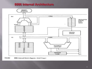
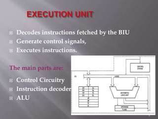
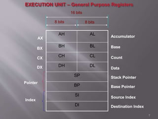
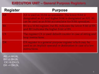
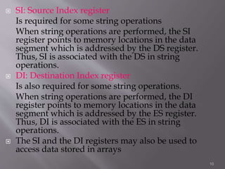
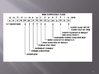
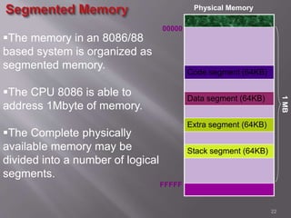
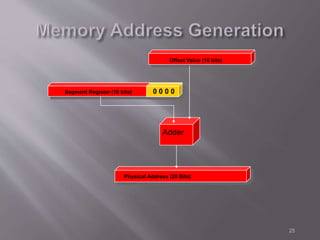
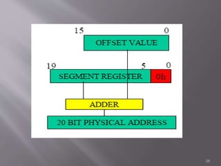
1
 It is a 16-bit μp.
 8086 has a 20 bit address bus can access up to
220 memory locations (1 MB).
 It can support up to 64K I/O ports.
 It provides 14, 16 -bit registers.
 Word size is 16 bits and double word size is 4
bytes.
 It has multiplexed address and data bus AD0-
AD15 and A16 – A19.
2
 8086 is designed to operate in two modes,
Minimum and Maximum.
 It can prefetches up to 6 instruction bytes from
memory and queues them in order to speed up
instruction execution.
 It requires +5V power supply.
 A 40 pin dual in line package.
 Address ranges from 00000H to FFFFFH
3
4
 8086 has two blocks BIU and EU.
 The BIU handles all transactions of data and addresses
on the buses for EU.
 The BIU performs all bus operations such as
instruction fetching, reading and writing operands for
memory and calculating the addresses of the memory
operands. The instruction bytes are transferred to the
instruction queue.
 EU executes instructions from the instruction system
byte queue.
 BIU contains Instruction queue, Segment registers,
Instruction pointer, Address adder.
 EU contains Control circuitry, Instruction decoder, ALU,
Pointer and Index register, Flag register.
5
 Decodes instructions fetched by the BIU
 Generate control signals,
 Executes instructions.
The main parts are:
 Control Circuitry
 Instruction decoder
 ALU
6
AH AL
BH BL
CH CL
DH DL
SP
BP
SI
DI
7
8 bits 8 bits
16 bits
Accumulator
Base
Count
Data
Stack Pointer
Base Pointer
Source Index
Destination Index
AX
BX
CX
DX
Pointer
Index
8 bits 8 bits
16 bits
Accumulator
Base
Count
Data
Stack Pointer
Base Pointer
Source Index
Destination Index
Register Purpose
AX AX is used as 16-bit accumulator. The lower 8-bit is
designated as AL and higher 8-bit is designated as AH. AL
can be used as an 8-bit accumulator for 8-bit operation.
BX BX is a 16 bit register, but BL indicates the lower 8-bit of BX
and BH indicates the higher 8-bit of BX.
CX The register CX is used default counter in case of string and
loop instructions.
DX DX register is a general purpose register which may be
used as an implicit operand or destination in case of a few
instructions.
8
AX --> AH,AL
BX --> BH,BL
CX --> CH,CL
DX --> DH,DL
 used to keep offset addresses.
 Used in various forms of memory addressing.
 In the case of SP and BP the default reference to form a
physical address is the Stack Segment (SS-will be discussed
under the BIU)
 The index registers (SI & DI) and the BX generally default
to the Data segment register (DS).
SP: Stack pointer
– This is stack pointer register pointing to program stack.
It is used in conjunction with SS for accessing the stack
segment
BP: Base Pointer
– This is base pointer register pointing to data in stack
segment. Unlike SP, we can use BP to access data in the
other segments
9
 SI: Source Index register
Is required for some string operations
When string operations are performed, the SI
register points to memory locations in the data
segment which is addressed by the DS register.
Thus, SI is associated with the DS in string
operations.
 DI: Destination Index register
Is also required for some string operations.
When string operations are performed, the DI
register points to memory locations in the data
segment which is addressed by the ES register.
Thus, DI is associated with the ES in string
operations.
 The SI and the DI registers may also be used to
access data stored in arrays
10
 A flag is a flip flop which indicates some conditions produced by
the execution of an instruction or controls certain operations of the
EU .
 In 8086 The EU contains
a 16 bit flag register
9 of the 16 are active flags and remaining 7 are undefined.
6 flags indicates some conditions- status flags and 3 are Control
Flags
 Flags Register determines the current state of the processor. They
are modified automatically by CPU after mathematical operations,
this allows to determine the type of the result, and to determine
conditions to transfer control to other parts of the program. 8086
has 9 flags and they are divided into two categories:
 Conditional Flags
 Control Flags
11
12
 Conditional Flags :
Conditional flags represent result of last arithmetic or logical
instruction executed. Conditional flags are as follows:
 Carry Flag (CF): This flag indicates an overflow condition
for unsigned integer arithmetic. It is also used in multiple-
precision arithmetic.
 Auxiliary Flag (AF): If an operation performed in ALU
generates a carry/barrow from lower nibble (i.e. D0 – D3)
to upper nibble (i.e. D4 – D7), the AF flag is set i.e. carry
given by D3 bit to D4 is AF flag. This is not a general-
purpose flag, it is used internally by the processor to perform
Binary to BCD conversion.
 Parity Flag (PF): This flag is used to indicate the parity of
result. If lower order 8-bits of the result contains even
number of 1’s, the Parity Flag is set and for odd number of
1’s, the Parity Flag is reset.
13
 Zero Flag (ZF): It is set; if the result of
arithmetic or logical operation is zero else it is
reset
 Sign Flag (SF): In sign magnitude format the
sign of number is indicated by MSB bit. If the
result of operation is negative, sign flag is set.
 Overflow Flag (OF): It occurs when signed
numbers are added or subtracted. An OF
indicates that the result has exceeded the
capacity of machine.
14
 Control Flags :
Control flags are set or reset deliberately to
control the operations of the execution unit.
Control flags are as follows:
 Trap Flag (TP):
 It is used for single step control.
 It allows user to execute one instruction of a program at a time
for debugging.
 When trap flag is set, program can be run in single step mode.
 Interrupt Flag (IF):
 It is an interrupt enable/disable flag.
 If it is set, the mask able interrupt of 8086 is enabled and if it is
reset, the interrupt is disabled.
 It can be set by executing instruction sit and can be cleared by
executing CLI instruction
15
 Direction Flag (DF):
 It is used in string operation.
 If it is set, string bytes are accessed from higher
memory address to lower memory address.
 When it is reset, the string bytes are accessed from
lower memory address to higher memory address.
16
 Six of the flags are status indicators reflecting
properties of the last arithmetic or logical
instruction.
 For example, if register AL = 7Fh and the
instruction ADD AL,1 is executed then the
following happen
AL = 80h
CF = 0; there is no carry out of bit 7
PF = 0; 80h has an odd number of ones
AF = 1; there is a carry out of bit 3 into bit 4
ZF = 0; the result is not zero
SF = 1; bit seven is one
OF = 1; the sign bit has changed
17
Contains
 6-byte Instruction Queue (Q)
 The Segment Registers (CS, DS, ES, SS).
 The Instruction Pointer (IP).
 The Address Summing block (Σ)
18
 The BIU uses a mechanism known as an
instruction stream queue to implement a pipeline
architecture.
 This queue permits pre-fetch of up to 6 bytes of
instruction code. Whenever the queue of the BIU
is not full, it has room for at least two more bytes
and at the same time the EU is not requesting it to
read or write operands from memory, the BIU is
free to look ahead in the program by pre-fetching
the next sequential instruction.
19
 In 8086/88 the processors have 4 segments
registers
 Code segment (CS) is a 16-bit register containing address of 64 KB
segment with processor instructions. The processor uses CS segment
for all accesses to instructions referenced by instruction pointer (IP)
register. CS register cannot be changed directly. The CS register is
automatically updated during far jump, far call and far return
instructions.
 Stack segment (SS) It is a 16-bit register containing address of 64KB segment
with program stack. By default, the processor assumes that all data referenced
by the stack pointer (SP) and base pointer (BP) registers is located in the stack
segment. SS register can be changed directly using POP instruction.
 Data segment (DS):It is a 16-bit register containing address of 64KB segment
with program data. By default, the processor assumes that all data referenced
by general registers (AX, BX, CX, DX) and index register (SI, DI) is located in
the data segment. DS register can be changed directly using POP and LDS
instructions
20
 Extra segment (ES)It is a 16-bit register containing address of
64KB segment, usually with program data. By default, the
processor assumes that the DI register references the ES
segment in string manipulation instructions. ES register can be
changed directly using POP and LES instructions. It is possible to
change default segments used by general and index registers by
prefixing instructions with a CS, SS, DS or ES prefix.
 IP (Instruction Pointer):-To access instructions the 8086 uses the
registers CS and IP. The CS register contains the segment number
of the next instruction and the IP contains the offset. IP is updated
each time an instruction is executed so that it will point to the next
instruction. Unlike other registers the IP can’t be directly
manipulated by an instruction, that is, an instruction may not
contain IP as its operand
21
Code segment (64KB)
Data segment (64KB)
Extra segment (64KB)
Stack segment (64KB)
22
1MB
The memory in an 8086/88
based system is organized as
segmented memory.
The CPU 8086 is able to
address 1Mbyte of memory.
The Complete physically
available memory may be
divided into a number of logical
segments.
00000
FFFFF
Physical Memory
 The 4 segments are Code, Data, Extra and Stack
segments.
 A Segment is a 64kbyte block of memory.
 The 16 bit contents of the segment registers in the
BIU actually point to the starting location of a
particular segment.
 A segment may be located any where in the
memory
 Each of these segments can be used for a specific
function
23
 Code segment of the memory, where the executable
program is stored.
 Data segment of the memory where the data is stored.
 Extra Segment which is another data segment in the
memory
 The stack segment is that segment of memory which is
used to store stack data.
 While addressing any location in the memory bank, the physical
address is calculated from two parts:
Physical address= segment address + offset address
 The second part is the offset value in that
segment.
24
25
Physical Address (20 Bits)
Adder
Segment Register (16 bits) 0 0 0 0
Offset Value (16 bits)
26
Thank-You
27

Arch 8086

  • 1.
  • 2.
     It isa 16-bit μp.  8086 has a 20 bit address bus can access up to 220 memory locations (1 MB).  It can support up to 64K I/O ports.  It provides 14, 16 -bit registers.  Word size is 16 bits and double word size is 4 bytes.  It has multiplexed address and data bus AD0- AD15 and A16 – A19. 2
  • 3.
     8086 isdesigned to operate in two modes, Minimum and Maximum.  It can prefetches up to 6 instruction bytes from memory and queues them in order to speed up instruction execution.  It requires +5V power supply.  A 40 pin dual in line package.  Address ranges from 00000H to FFFFFH 3
  • 4.
  • 5.
     8086 hastwo blocks BIU and EU.  The BIU handles all transactions of data and addresses on the buses for EU.  The BIU performs all bus operations such as instruction fetching, reading and writing operands for memory and calculating the addresses of the memory operands. The instruction bytes are transferred to the instruction queue.  EU executes instructions from the instruction system byte queue.  BIU contains Instruction queue, Segment registers, Instruction pointer, Address adder.  EU contains Control circuitry, Instruction decoder, ALU, Pointer and Index register, Flag register. 5
  • 6.
     Decodes instructionsfetched by the BIU  Generate control signals,  Executes instructions. The main parts are:  Control Circuitry  Instruction decoder  ALU 6
  • 7.
    AH AL BH BL CHCL DH DL SP BP SI DI 7 8 bits 8 bits 16 bits Accumulator Base Count Data Stack Pointer Base Pointer Source Index Destination Index AX BX CX DX Pointer Index 8 bits 8 bits 16 bits Accumulator Base Count Data Stack Pointer Base Pointer Source Index Destination Index
  • 8.
    Register Purpose AX AXis used as 16-bit accumulator. The lower 8-bit is designated as AL and higher 8-bit is designated as AH. AL can be used as an 8-bit accumulator for 8-bit operation. BX BX is a 16 bit register, but BL indicates the lower 8-bit of BX and BH indicates the higher 8-bit of BX. CX The register CX is used default counter in case of string and loop instructions. DX DX register is a general purpose register which may be used as an implicit operand or destination in case of a few instructions. 8 AX --> AH,AL BX --> BH,BL CX --> CH,CL DX --> DH,DL
  • 9.
     used tokeep offset addresses.  Used in various forms of memory addressing.  In the case of SP and BP the default reference to form a physical address is the Stack Segment (SS-will be discussed under the BIU)  The index registers (SI & DI) and the BX generally default to the Data segment register (DS). SP: Stack pointer – This is stack pointer register pointing to program stack. It is used in conjunction with SS for accessing the stack segment BP: Base Pointer – This is base pointer register pointing to data in stack segment. Unlike SP, we can use BP to access data in the other segments 9
  • 10.
     SI: SourceIndex register Is required for some string operations When string operations are performed, the SI register points to memory locations in the data segment which is addressed by the DS register. Thus, SI is associated with the DS in string operations.  DI: Destination Index register Is also required for some string operations. When string operations are performed, the DI register points to memory locations in the data segment which is addressed by the ES register. Thus, DI is associated with the ES in string operations.  The SI and the DI registers may also be used to access data stored in arrays 10
  • 11.
     A flagis a flip flop which indicates some conditions produced by the execution of an instruction or controls certain operations of the EU .  In 8086 The EU contains a 16 bit flag register 9 of the 16 are active flags and remaining 7 are undefined. 6 flags indicates some conditions- status flags and 3 are Control Flags  Flags Register determines the current state of the processor. They are modified automatically by CPU after mathematical operations, this allows to determine the type of the result, and to determine conditions to transfer control to other parts of the program. 8086 has 9 flags and they are divided into two categories:  Conditional Flags  Control Flags 11
  • 12.
  • 13.
     Conditional Flags: Conditional flags represent result of last arithmetic or logical instruction executed. Conditional flags are as follows:  Carry Flag (CF): This flag indicates an overflow condition for unsigned integer arithmetic. It is also used in multiple- precision arithmetic.  Auxiliary Flag (AF): If an operation performed in ALU generates a carry/barrow from lower nibble (i.e. D0 – D3) to upper nibble (i.e. D4 – D7), the AF flag is set i.e. carry given by D3 bit to D4 is AF flag. This is not a general- purpose flag, it is used internally by the processor to perform Binary to BCD conversion.  Parity Flag (PF): This flag is used to indicate the parity of result. If lower order 8-bits of the result contains even number of 1’s, the Parity Flag is set and for odd number of 1’s, the Parity Flag is reset. 13
  • 14.
     Zero Flag(ZF): It is set; if the result of arithmetic or logical operation is zero else it is reset  Sign Flag (SF): In sign magnitude format the sign of number is indicated by MSB bit. If the result of operation is negative, sign flag is set.  Overflow Flag (OF): It occurs when signed numbers are added or subtracted. An OF indicates that the result has exceeded the capacity of machine. 14
  • 15.
     Control Flags: Control flags are set or reset deliberately to control the operations of the execution unit. Control flags are as follows:  Trap Flag (TP):  It is used for single step control.  It allows user to execute one instruction of a program at a time for debugging.  When trap flag is set, program can be run in single step mode.  Interrupt Flag (IF):  It is an interrupt enable/disable flag.  If it is set, the mask able interrupt of 8086 is enabled and if it is reset, the interrupt is disabled.  It can be set by executing instruction sit and can be cleared by executing CLI instruction 15
  • 16.
     Direction Flag(DF):  It is used in string operation.  If it is set, string bytes are accessed from higher memory address to lower memory address.  When it is reset, the string bytes are accessed from lower memory address to higher memory address. 16
  • 17.
     Six ofthe flags are status indicators reflecting properties of the last arithmetic or logical instruction.  For example, if register AL = 7Fh and the instruction ADD AL,1 is executed then the following happen AL = 80h CF = 0; there is no carry out of bit 7 PF = 0; 80h has an odd number of ones AF = 1; there is a carry out of bit 3 into bit 4 ZF = 0; the result is not zero SF = 1; bit seven is one OF = 1; the sign bit has changed 17
  • 18.
    Contains  6-byte InstructionQueue (Q)  The Segment Registers (CS, DS, ES, SS).  The Instruction Pointer (IP).  The Address Summing block (Σ) 18
  • 19.
     The BIUuses a mechanism known as an instruction stream queue to implement a pipeline architecture.  This queue permits pre-fetch of up to 6 bytes of instruction code. Whenever the queue of the BIU is not full, it has room for at least two more bytes and at the same time the EU is not requesting it to read or write operands from memory, the BIU is free to look ahead in the program by pre-fetching the next sequential instruction. 19
  • 20.
     In 8086/88the processors have 4 segments registers  Code segment (CS) is a 16-bit register containing address of 64 KB segment with processor instructions. The processor uses CS segment for all accesses to instructions referenced by instruction pointer (IP) register. CS register cannot be changed directly. The CS register is automatically updated during far jump, far call and far return instructions.  Stack segment (SS) It is a 16-bit register containing address of 64KB segment with program stack. By default, the processor assumes that all data referenced by the stack pointer (SP) and base pointer (BP) registers is located in the stack segment. SS register can be changed directly using POP instruction.  Data segment (DS):It is a 16-bit register containing address of 64KB segment with program data. By default, the processor assumes that all data referenced by general registers (AX, BX, CX, DX) and index register (SI, DI) is located in the data segment. DS register can be changed directly using POP and LDS instructions 20
  • 21.
     Extra segment(ES)It is a 16-bit register containing address of 64KB segment, usually with program data. By default, the processor assumes that the DI register references the ES segment in string manipulation instructions. ES register can be changed directly using POP and LES instructions. It is possible to change default segments used by general and index registers by prefixing instructions with a CS, SS, DS or ES prefix.  IP (Instruction Pointer):-To access instructions the 8086 uses the registers CS and IP. The CS register contains the segment number of the next instruction and the IP contains the offset. IP is updated each time an instruction is executed so that it will point to the next instruction. Unlike other registers the IP can’t be directly manipulated by an instruction, that is, an instruction may not contain IP as its operand 21
  • 22.
    Code segment (64KB) Datasegment (64KB) Extra segment (64KB) Stack segment (64KB) 22 1MB The memory in an 8086/88 based system is organized as segmented memory. The CPU 8086 is able to address 1Mbyte of memory. The Complete physically available memory may be divided into a number of logical segments. 00000 FFFFF Physical Memory
  • 23.
     The 4segments are Code, Data, Extra and Stack segments.  A Segment is a 64kbyte block of memory.  The 16 bit contents of the segment registers in the BIU actually point to the starting location of a particular segment.  A segment may be located any where in the memory  Each of these segments can be used for a specific function 23
  • 24.
     Code segmentof the memory, where the executable program is stored.  Data segment of the memory where the data is stored.  Extra Segment which is another data segment in the memory  The stack segment is that segment of memory which is used to store stack data.  While addressing any location in the memory bank, the physical address is calculated from two parts: Physical address= segment address + offset address  The second part is the offset value in that segment. 24
  • 25.
    25 Physical Address (20Bits) Adder Segment Register (16 bits) 0 0 0 0 Offset Value (16 bits)
  • 26.
  • 27.

Editor's Notes