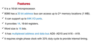
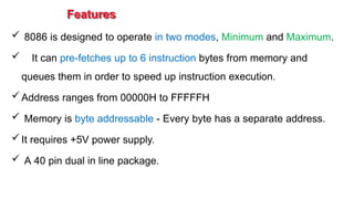
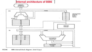
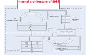
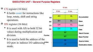
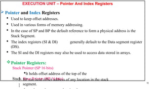
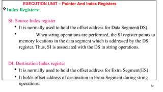
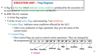
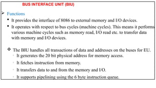
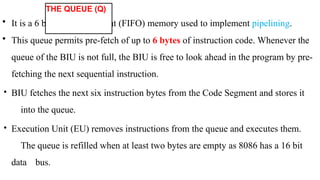
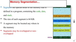
The document outlines the architecture and features of the Intel 8086 microprocessor, which is a 16-bit microprocessor with a 20-bit address bus capable of accessing up to 1 MB of memory. It describes the internal architecture, including the execution unit (EU) and bus interface unit (BIU), and details the function of various registers and memory segmentation. Additionally, it explains the organization of instructions, addressing modes, and how the microprocessor handles data and instruction execution efficiently using pipelining.


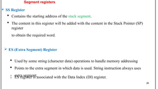


![Getting Started with Apache Spark: Big Data Made Simple [Free Meetup]](https://cdn.slidesharecdn.com/ss_thumbnails/apachesparkgettingstarted-260203175547-8361bcc3-thumbnail.jpg?width=640&height=640&fit=bounds)

