Downloaded 126 times


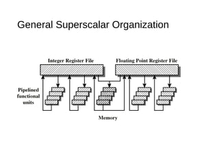
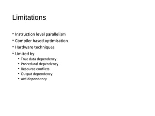
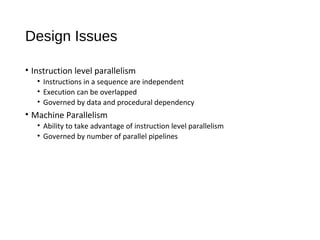
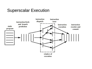
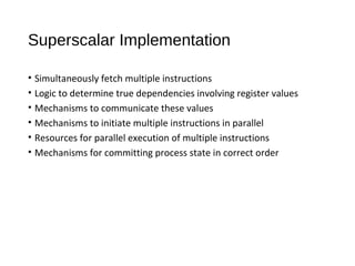
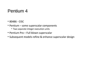
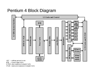
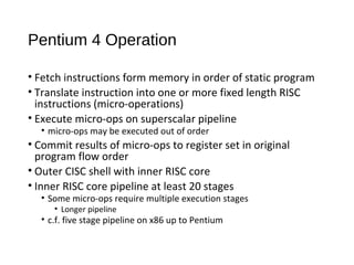
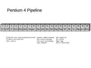
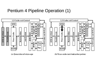
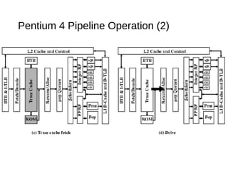
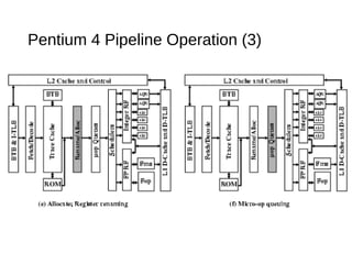
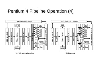
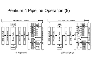
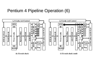
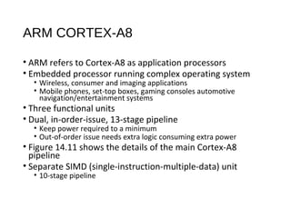
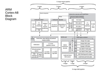

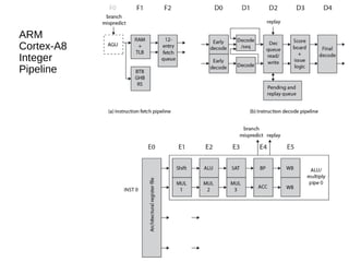
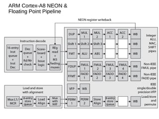

This document discusses instruction level parallelism (ILP) and the design of superscalar processors, highlighting their ability to execute multiple instructions simultaneously by overlapping instruction fetching and execution. It elaborates on challenges such as dependencies and resource conflicts, along with strategies like register renaming and out-of-order execution to maximize efficiency. It also provides specific examples of processor architectures, including the Pentium and ARM Cortex-A8, illustrating their execution pipelines and methodologies for optimizing performance.