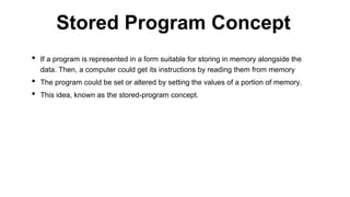
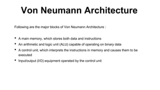
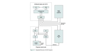
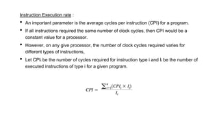
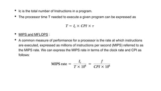
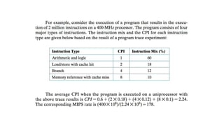
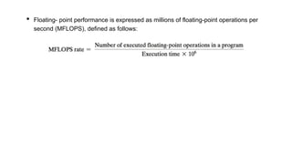
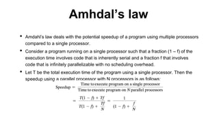
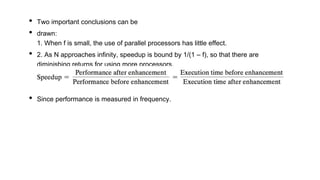
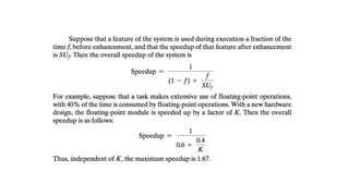
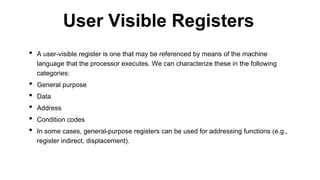
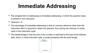
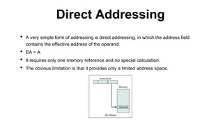
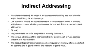
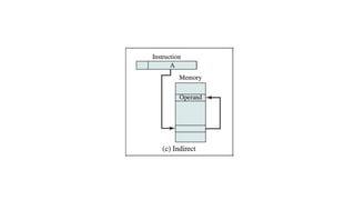
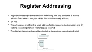
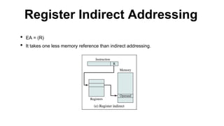
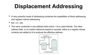
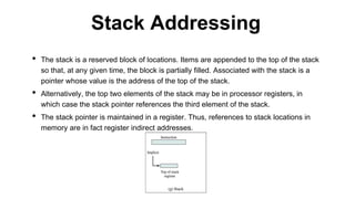
This document discusses processor organization and architecture. It covers the stored program concept where both instructions and data are stored in memory. It describes the Von Neumann architecture, which includes a main memory, ALU, control unit, and I/O. It discusses the registers used in processor control and execution like the program counter, accumulator, and instruction register. Finally, it examines addressing modes like immediate, direct, indirect, register, displacement, and stack addressing.
2. • If a program is represented in a form suitable for storing in memory alongside the
data. Then, a computer could get its instructions by reading them from memory
• The program could be set or altered by setting the values of a portion of memory.
• This idea, known as the stored-program concept.
Stored Program Concept
3. Following are the major blocks of Von Neumann Architecture :
• A main memory, which stores both data and instructions
• An arithmetic and logic unit (ALU) capable of operating on binary data
• A control unit, which interprets the instructions in memory and causes them to be
executed
• Input/output (I/O) equipment operated by the control unit
Von Neumann Architecture
4.
5. • Memory buffer register(MBR) : Contains a word to be stored in memory or sent to the
I/O unit, or is used to receive a word from memory or from the I/O unit.
• Memory address register (MAR) : Specifies the address in memory of the word to be
written from or read into the MBR.
• Instruction register(IR) : Contains the 8-bit opcode of the instruction being executed.
• Instruction buffer register (IBR) : Employed to hold temporarily the right-
hand instruction from a word in memory.
6. • Program counter (PC) : Contains the address of the next instruction pair to be fetched
from memory.
• Accumulator (AC) and multiplier quotient (MQ) : Employed to hold tem- porarily
operands and results of ALU operations. For example, the result of multiplying two 40-
bit numbers is an 80-bit number; the most significant 40 bits are stored in the AC and
the least significant in the MQ.
7. • Raw speed is far less important than how a processor performs when executing a
given application.
• Unfortunately, application performance depends not just on the raw speed of the
processor but also on the instruction set, choice of implementation language,
efficiency of the compiler, and skill of the programming done to implement the
application.
• CPU Clock Speed : At the most fundamental level, the speed of a processor is
dictated by the pulse frequency produced by the clock, measured in cycles per
second, or Hertz (Hz).
Performance Assessment
8. Instruction Execution rate :
• An important parameter is the average cycles per instruction (CPI) for a program.
• If all instructions required the same number of clock cycles, then CPI would be a
constant value for a processor.
• However, on any give processor, the number of clock cycles required varies for
different types of instructions,
• Let CPIi be the number of cycles required for instruction type i and Ii be the number of
executed instructions of type i for a given program.
9. • Ic is the total number of Instructions in a program.
• The processor time T needed to execute a given program can be expressed as
• MIPS and MFLOPS :
• A common measure of performance for a processor is the rate at which instructions
are executed, expressed as millions of instructions per second (MIPS) referred to as
the MIPS rate. We can express the MIPS rate in terms of the clock rate and CPI as
follows:
10.
11. • Floating- point performance is expressed as millions of floating-point operations per
second (MFLOPS), defined as follows:
12. • Amdahl’s law deals with the potential speedup of a program using multiple processors
compared to a single processor.
• Consider a program running on a single processor such that a fraction (1 – f) of the
execution time involves code that is inherently serial and a fraction f that involves
code that is infinitely parallelizable with no scheduling overhead.
• Let T be the total execution time of the program using a single processor. Then the
speedup using a parallel processor with N processors is as follows:
Amhdal’s law
13. • Two important conclusions can be
• drawn:
1. When f is small, the use of parallel processors has little effect.
• 2. As N approaches infinity, speedup is bound by 1/(1 – f), so that there are
diminishing returns for using more processors.
• Since performance is measured in frequency.
14.
15. • A user-visible register is one that may be referenced by means of the machine
language that the processor executes. We can characterize these in the following
categories:
• General purpose
• Data
• Address
• Condition codes
• In some cases, general-purpose registers can be used for addressing functions (e.g.,
register indirect, displacement).
User Visible Registers
16. • In other cases, there is a partial or clean separation between data registers and
address registers.
• Data registers may be used only to hold data and cannot be employed in the
calculation of an operand address.
• Segment pointers : In a machine with segmented addressing ,a segment register
holds the address of the base of the segment.
• Stack pointer : If there is user-visible stack addressing, then typically there is a
dedicated register that points to the top of the stack.
• A final category of registers, which is at least partially visible to the user, holds
condition codes (also referred to as flags).
• Condition codes are bits set by the processor hardware as the result of operations.
• In addition to the result itself being stored in a register or memory, a condition code is
also set. The code may subsequently be tested as part of a conditional branch
operation.
17. • There are a variety of processor registers that are employed to control the operation
of the processor. Most of these, on most machines, are not visible to the user.
• Four registers are essential to instruction execution:
• Program counter (PC) : Contains the address of an instruction to be fetched.
• Instruction register (IR) : Contains the instruction most recently fetched.
• Memory address register (MAR) : Contains the address of a location in memory.
• Memory buffer register (MBR) : Contains a word of data to be written to memory or
the word most recently read.
Control and Status Registers
18. • Many processor designs include a register or set of registers, often known as the
program status word (PSW), that contain condition codes plus other status
information.
• Common fields or flags include the following:
• Sign
• Zero
• Carry
• Equal
• Overflow
• Interrupt Enable/Disable : Used to enable or disable interrupts.
• Supervisor : Indicates whether the processor is executing in supervisor or user
mode. Certain privileged instructions can be executed only in supervisor mode,
and certain areas of memory can be accessed only in supervisor mode.
19. • In a pipeline, new inputs are accepted at one end before previously accepted inputs appear as
outputs at the other end.
• Let us consider the following decomposition of the instruction processing.
• Fetch instruction (FI) : Read the next expected instruction into a buffer.
• Decode instruction (DI) : Determine the opcode and the operand specifiers.
• Calculate operands (CO) : Calculate the effective address of each source oper- and. This may
involve displacement, register indirect, indirect, or other forms of address calculation.
• Fetch operands (FO) : Fetch each operand from memory. Operands in regis- ters need not be
fetched.
• Execute instruction (EI) : Perform the indicated operation and store the result, if any, in the
specified destination operand location.
• Write operand (WO) : Store the result in memory.
Pipelining Strategy
20.
21. • The cycle time T(tau) of an instruction pipeline is the time needed to advance a set of
instructions one stage through the pipeline
• The cycle time can be determined as
Pipeline performance
22. • The speedup factor for the instruction pipeline compared to execution without the
pipeline is defined as
23. • A pipeline hazard occurs when the pipeline, or some portion of the pipeline, must stall
because conditions do not permit continued execution.
• Resource Hazards :
• A resource hazard occurs when two (or more) instructions that are already in the
pipeline need the same resource. The result is that the instructions must be executed
in serial rather than parallel for a portion of the pipeline.
• Another example of a resource conflict is a situation in which multiple instructions are
ready to enter the execute instruction phase and there is a single ALU.
• One solutions to such resource hazards is to increase available resources, such as
having multiple ports into main memory and multiple ALU units.
Pipelining hazards
24. Resource Hazard
FI DI CO FO EI WO
I1
I2 I1
I3 I2 I1
- I3 I2 I1
- - I3 I2 I1
- - - I3 I2 I1
I4 - - - I3 I2
25. • Data Hazards :
• A data hazard occurs when there is a conflict in the access of an operand location.
• There are three types of data hazards;
• Read after write (RAW), or true dependency : An instruction modifies a reg- ister or
memory location and a succeeding instruction reads the data in that memory or
register location. A hazard occurs if the read takes place before the write operation is
complete.
• Write after read (WAR),or anti dependency : A hazard occurs if the write operation
completes before the read operation takes place.
• Write after write (WAW), or output dependency : Two instructions both write to the
same location. A hazard occurs if the write operations take place in the reverse order
of the intended sequence.
26. • Control Hazards :
• A control hazard, also known as a branch hazard, occurs when the pipeline makes
the wrong decision on a branch prediction and therefore brings instructions into the
pipeline that must subsequently be discarded.
27. • The simplest form of addressing is immediate addressing, in which the operand value
is present in the instruction
• Operand = A
• The advantage of immediate addressing is that no memory reference other than the
instruction fetch is required to obtain the operand, thus saving one memory or cache
cycle in the instruction cycle.
• The disadvantage is that the size of the number is restricted to the size of the address
field, which, in most instruction sets, is small compared with the word length.
Immediate Addressing
28. • A very simple form of addressing is direct addressing, in which the address field
contains the effective address of the operand:
• EA = A
• It requires only one memory reference and no special calculation.
• The obvious limitation is that it provides only a limited address space.
Direct Addressing
29. • With direct addressing, the length of the address field is usually less than the word
length, thus limiting the address range.
• One solution is to have the address field refer to the address of a word in memory,
which in turn contains a full-length address of the operand. This is known as indirect
addressing:
• EA = (A)
• The parentheses are to be interpreted as meaning contents of.
• The obvious advantage of this approach is that for a word length of N, an address
space of 2N is now available.
• The disadvantage is that instruction execution requires two memory references to fetch
the operand: one to get its address and a second to get its value.
Indirect Addressing
30.
31. • Register addressing is similar to direct addressing. The only difference is that the
address field refers to a register rather than a main memory address:
• EA = R
• The advantages are (1) only a small address field is needed in the instruction, and (2)
no time-consuming memory references are required.
• The disadvantage of register addressing is that the address space is very limited.
Register Addressing
32. • EA = (R)
• It takes one less memory reference than indirect addressing.
Register Indirect Addressing
33. • A very powerful mode of addressing combines the capabilities of direct addressing
and register indirect addressing.
• EA = A + (R)
• The value contained in one address field (value = A) is used directly. The other
address field, or an implicit reference based on opcode, refers to a register whose
contents are added to A to produce the effective address.
Displacement Addressing
34. • The stack is a reserved block of locations. Items are appended to the top of the stack
so that, at any given time, the block is partially filled. Associated with the stack is a
pointer whose value is the address of the top of the stack.
• Alternatively, the top two elements of the stack may be in processor registers, in
which case the stack pointer references the third element of the stack.
• The stack pointer is maintained in a register. Thus, references to stack locations in
memory are in fact register indirect addresses.
Stack Addressing