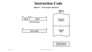
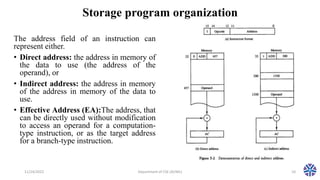
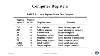
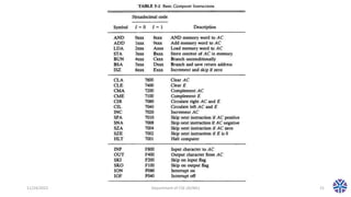
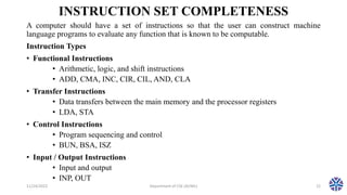
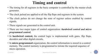
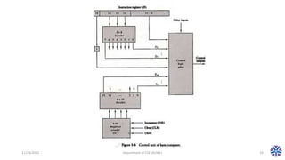
CS307PC:Computer Organization
and Architecture (R18 II(I sem))
Department of computer science and engineering
(AI/ML)
Session 5
by
Asst.Prof.M.Gokilavani
VITS
11/24/2022 Department of CSE (AI/ML) 1
TEXT BOOK:
• 1. Computer System Architecture – M. Moris Mano, Third Edition,
Pearson/PHI.
REFERENCES:
• Computer Organization – Car Hamacher, Zvonks Vranesic, Safea
Zaky, Vth Edition, McGraw Hill.
• Computer Organization and Architecture – William Stallings Sixth
Edition, Pearson/PHI.
• Structured Computer Organization – Andrew S. Tanenbaum, 4th
Edition, PHI/Pearson.
11/24/2022 Department of CSE (AI/ML) 2
UNIT - I
11/24/2022 Department of CSE (AI/ML) 3
Digital Computers: Introduction, Block diagram of Digital Computer,
Definition of Computer Organization, Computer Design and Computer
Architecture.
Register Transfer Language and Micro operations: Register Transfer
language, Register Transfer, Bus and memory transfers, Arithmetic
Micro operations, logic micro operations, shift micro operations,
Arithmetic logic shift unit.
Basic Computer Organization and Design: Instruction codes,
Computer Registers Computer instructions, Timing and Control,
Instruction cycle, Memory Reference Instructions, Input – Output and
Interrupt.
Topics covered in session 5
• Basic Computer Organization and Design
• Instruction codes
• Computer Registers Computer instructions
• Timing and Control
• Instruction cycle
• Memory Reference Instructions
• Input – Output and Interrupt
11/24/2022 Department of CSE (AI/ML) 4
Description of basic computer
• Computers are the digital devices that performs the various computational task.
• Digital means there is the process of representing the information by the help of
the certain discrete values.
• Information is represented in digital computers in terms of bits.
• By various coding techniques these groups of bits can not only represent numbers
but also other discrete symbols
• A computer system is sub-divided into two functional entities:
• hardware and software
• Hardware consists of all electronics components.
• Software consists of instruction and data that the computer manipulate to perform
various tasks.
11/24/2022 Department of CSE (AI/ML) 5
Description of basic computer
• Application software is all the computer software that
causes a computer to perform useful tasks beyond the running
of the computer itself.
• System software is computer software designed to operate
and control the computer hardware and to provide a platform
for running application software.
• Computer hardware is the collection of physical elements
that comprise a computer system.
• Hardware consist of three major parts:
• CPU: It has ALU for manipulating data, registers for storing data
and control circuit for generating control signals.
• Memory: It store instruction and data.
• I/O Processor: It contain electronic circuit for communicating and
controlling information flow between computer and input or output
devices.
11/24/2022 Department of CSE (AI/ML) 6
INSTRUCTIONS Program A sequence of (machine)
instructions
• Program
A sequence of (machine) instructions(Machine)
• Instruction
A group of bits that tell the computer to perform a specific operation (a
sequence of micro-operation).
• The instructions of a program, along with any needed data are stored
in memory
• The CPU reads the next instruction from memory.
• It is placed in an Instruction Register (IR)
• Control circuitry in control unit then translates the instruction into
the sequence of micro operations necessary to implement it.
11/24/2022 Department of CSE (AI/ML) 7
Instruction Code
• A computer instruction is often divided into two parts.
• An opcode (Operation Code) that specifies the operation for that
instruction.
• An address that specifies the registers and/or locations in memory to use
for that operation.
• In the Basic Computer, since the memory contains 4096 (= 212) words, we needs
12 bit to specify which memory address this instruction will use.
• In the Basic Computer, bit 15 of the instruction specifies the addressing mode (0:
direct addressing, 1: indirect addressing).
• Since the memory words, and hence the instructions, are 16 bits long, that leaves 3
bits for the instruction’s opcode.
11/24/2022 Department of CSE (AI/ML) 8
Instruction Code
11/24/2022 Department of CSE (AI/ML) 9
Storage program organization
The address field of an instruction can
represent either.
• Direct address: the address in memory of
the data to use (the address of the
operand), or
• Indirect address: the address in memory
of the address in memory of the data to
use.
• Effective Address (EA):The address, that
can be directly used without modification
to access an operand for a computation-
type instruction, or as the target address
for a branch-type instruction.
11/24/2022 Department of CSE (AI/ML) 10
Direct and indirect addressing
• In direct address the address field in the instruction gives the address of the
operand, In case of the indirect address, the address in the address field gives an
address of the memory word in which address operand is found.
• Direct and indirect address are separated by bit I. I is 1 for indirect and o for
direct.
• In direct address, content of the address field gives the effective address which is
457 in the given example.
• In indirect address, the word in the memory address specified in the address field
gives the effective address which is 1350 in the given example.
11/24/2022 Department of CSE (AI/ML) 11
Computer Registers
11/24/2022 Department of CSE (AI/ML) 12
Computer Registers
11/24/2022 Department of CSE (AI/ML) 13
Computer Registers
• A processor has many registers to hold instructions, addresses, data, etc.
• The processor has a register, the Program Counter (PC) that holds the memory
address of the next instruction to get.
• Since the memory in the Basic Computer only has 4096 locations, the PC only
needs 12 bits.
• In a direct or indirect addressing, the processor needs to keep track of what
locations in memory it is addressing: The Address Register (AR) is used for this.
• The AR is a 12 bit register in the Basic Computer.
• When an operand is found, using either direct or indirect addressing, it is placed in
the Data Register (DR). The processor then uses this value as data for its
operation.
• The Basic Computer has a single general purpose register – the
Accumulator (AC).
11/24/2022 Department of CSE (AI/ML) 14
Computer Registers
• The significance of a general purpose register is that it can be referred to in
instructions.
• e.g. load AC with the contents of a specific memory location; store the
contents of AC into a specified memory location.
• Often a processor will need a scratch register to store intermediate results or other
temporary data; in the Basic Computer this is the Temporary Register (TR).
• The Basic Computer uses a very simple model of input/output (I/O) operations.
• Input devices are considered to send 8 bits of character data to the
processor.
• The processor can send 8 bits of character data to output devices.
• The Input Register (INPR) holds an 8 bit character gotten from an input
device.
• The Output Register (OUTR) holds an 8 bit character to be send to an
output device
11/24/2022 Department of CSE (AI/ML) 15
Common Bus System
• The basic computer has eight register, memory unit and control unit.
• Path must be provided to transfer information from one register to another and
from memory to the register.
• The number of wires will be excessive if the connection is made between the
output of each register and input of other.
• A more efficient scheme in transferring information in a system having many
register is to use a common bus.
• The output of th seven registers and memory are connected to the common bus
system.
11/24/2022 Department of CSE (AI/ML) 16
Common Bus System
11/24/2022 Department of CSE (AI/ML) 17
Common Bus System
• The specific output that is selected for the bus lines at any given time is determined from
the binary value of the selection variables S2,S1 and S0.
• The numbers along each output shows the decimal equivalent of the required binary
selection.
• The lines from the common bus are connected to the inputs of each register and data input
of the memory.
• The particular register whose LD(load) input is enabled receives the data from the bus
during the next clock transition.
• The memory receives the content of the bus when its write input is activated.
11/24/2022 Department of CSE (AI/ML) 18
Computer Instructions
11/24/2022 Department of CSE (AI/ML) 19
Computer Instructions
• A memory reference instruction uses 12 bits to specify the an address and one
bit to specify the addressing mode.
• A register reference instruction specifies an operation on or a test of the AC
register. 12 bits are used to specify the operation or test to be executed.
• In the case of i/o instruction also 12 bits are used to specify the type of i/o
operation or test performed.
• Hex code of i/o instruction starts with F.
• Hex code of register reference instruction starts with the 7.
• Hex code of direct memory reference instruction starts with 0-6.
• Hex code of indirect memory reference instruction starts with 8-E.
11/24/2022 Department of CSE (AI/ML) 20
11/24/2022 Department of CSE (AI/ML) 21
INSTRUCTION SET COMPLETENESS
A computer should have a set of instructions so that the user can construct machine
language programs to evaluate any function that is known to be computable.
Instruction Types
• Functional Instructions
• Arithmetic, logic, and shift instructions
• ADD, CMA, INC, CIR, CIL, AND, CLA
• Transfer Instructions
• Data transfers between the main memory and the processor registers
• LDA, STA
• Control Instructions
• Program sequencing and control
• BUN, BSA, ISZ
• Input / Output Instructions
• Input and output
• INP, OUT
11/24/2022 Department of CSE (AI/ML) 22
Timing and control
• The timing for all registers in the basic computer is controlled by the master clock
generator.
• The clock pulsed are applied to all the flip flops and registers in the system.
• The clock pulses do not change the state of register unless enabled by control
signals.
• These signals are generated in the control unit.
• There are two major types of control organization: hardwired control and micro
programmed control.
• In hardwired control, the control logic is implemented with gates, flip flops,
decoders and other digital circuits.
• In micro programmed organization, the control information is stored in a control
memory. The control memory is programmed to initiate the required sequence of
micro operation.
11/24/2022 Department of CSE (AI/ML) 23
11/24/2022 Department of CSE (AI/ML) 24
11/24/2022 Department of CSE (AI/ML) 25
Hardwired Control Unit
• It consists of two decoders , sequence counter and number of control
logic gates.
• An instruction read from memory is places in IR.
• Opcode of the instruction derives one of the output of opcode decoder
high.
• At first SC is cleared to zero. As the first clock pulse hits the output of
counter and hence counter decoder change and produce sequence of
timing signals T0,T1,T2 and so on.
11/24/2022 Department of CSE (AI/ML) 26
Hardwired Control Unit
• The output of counter decoder and decoded opcode of the instruction
causes the control logic to generate a particular control word for the
operation.
• At the end of each instruction, counter is cleared.
• For the next instruction, the opcode produces different output on the
opcode decoder and the control will be different and the control unit
will perform the different tasks.
11/24/2022 Department of CSE (AI/ML) 27
Topics to be covered in next session 6
• Instruction cycle
11/24/2022 Department of CSE (AI/ML) 28
Thank you!!!

CS304PC:Computer Organization and Architecture Session 5 Basic Computer Organization and Design.pptx

  • 1.
    CS307PC:Computer Organization and Architecture(R18 II(I sem)) Department of computer science and engineering (AI/ML) Session 5 by Asst.Prof.M.Gokilavani VITS 11/24/2022 Department of CSE (AI/ML) 1
  • 2.
    TEXT BOOK: • 1.Computer System Architecture – M. Moris Mano, Third Edition, Pearson/PHI. REFERENCES: • Computer Organization – Car Hamacher, Zvonks Vranesic, Safea Zaky, Vth Edition, McGraw Hill. • Computer Organization and Architecture – William Stallings Sixth Edition, Pearson/PHI. • Structured Computer Organization – Andrew S. Tanenbaum, 4th Edition, PHI/Pearson. 11/24/2022 Department of CSE (AI/ML) 2
  • 3.
    UNIT - I 11/24/2022Department of CSE (AI/ML) 3 Digital Computers: Introduction, Block diagram of Digital Computer, Definition of Computer Organization, Computer Design and Computer Architecture. Register Transfer Language and Micro operations: Register Transfer language, Register Transfer, Bus and memory transfers, Arithmetic Micro operations, logic micro operations, shift micro operations, Arithmetic logic shift unit. Basic Computer Organization and Design: Instruction codes, Computer Registers Computer instructions, Timing and Control, Instruction cycle, Memory Reference Instructions, Input – Output and Interrupt.
  • 4.
    Topics covered insession 5 • Basic Computer Organization and Design • Instruction codes • Computer Registers Computer instructions • Timing and Control • Instruction cycle • Memory Reference Instructions • Input – Output and Interrupt 11/24/2022 Department of CSE (AI/ML) 4
  • 5.
    Description of basiccomputer • Computers are the digital devices that performs the various computational task. • Digital means there is the process of representing the information by the help of the certain discrete values. • Information is represented in digital computers in terms of bits. • By various coding techniques these groups of bits can not only represent numbers but also other discrete symbols • A computer system is sub-divided into two functional entities: • hardware and software • Hardware consists of all electronics components. • Software consists of instruction and data that the computer manipulate to perform various tasks. 11/24/2022 Department of CSE (AI/ML) 5
  • 6.
    Description of basiccomputer • Application software is all the computer software that causes a computer to perform useful tasks beyond the running of the computer itself. • System software is computer software designed to operate and control the computer hardware and to provide a platform for running application software. • Computer hardware is the collection of physical elements that comprise a computer system. • Hardware consist of three major parts: • CPU: It has ALU for manipulating data, registers for storing data and control circuit for generating control signals. • Memory: It store instruction and data. • I/O Processor: It contain electronic circuit for communicating and controlling information flow between computer and input or output devices. 11/24/2022 Department of CSE (AI/ML) 6
  • 7.
    INSTRUCTIONS Program Asequence of (machine) instructions • Program A sequence of (machine) instructions(Machine) • Instruction A group of bits that tell the computer to perform a specific operation (a sequence of micro-operation). • The instructions of a program, along with any needed data are stored in memory • The CPU reads the next instruction from memory. • It is placed in an Instruction Register (IR) • Control circuitry in control unit then translates the instruction into the sequence of micro operations necessary to implement it. 11/24/2022 Department of CSE (AI/ML) 7
  • 8.
    Instruction Code • Acomputer instruction is often divided into two parts. • An opcode (Operation Code) that specifies the operation for that instruction. • An address that specifies the registers and/or locations in memory to use for that operation. • In the Basic Computer, since the memory contains 4096 (= 212) words, we needs 12 bit to specify which memory address this instruction will use. • In the Basic Computer, bit 15 of the instruction specifies the addressing mode (0: direct addressing, 1: indirect addressing). • Since the memory words, and hence the instructions, are 16 bits long, that leaves 3 bits for the instruction’s opcode. 11/24/2022 Department of CSE (AI/ML) 8
  • 9.
  • 10.
    Storage program organization Theaddress field of an instruction can represent either. • Direct address: the address in memory of the data to use (the address of the operand), or • Indirect address: the address in memory of the address in memory of the data to use. • Effective Address (EA):The address, that can be directly used without modification to access an operand for a computation- type instruction, or as the target address for a branch-type instruction. 11/24/2022 Department of CSE (AI/ML) 10
  • 11.
    Direct and indirectaddressing • In direct address the address field in the instruction gives the address of the operand, In case of the indirect address, the address in the address field gives an address of the memory word in which address operand is found. • Direct and indirect address are separated by bit I. I is 1 for indirect and o for direct. • In direct address, content of the address field gives the effective address which is 457 in the given example. • In indirect address, the word in the memory address specified in the address field gives the effective address which is 1350 in the given example. 11/24/2022 Department of CSE (AI/ML) 11
  • 12.
  • 13.
  • 14.
    Computer Registers • Aprocessor has many registers to hold instructions, addresses, data, etc. • The processor has a register, the Program Counter (PC) that holds the memory address of the next instruction to get. • Since the memory in the Basic Computer only has 4096 locations, the PC only needs 12 bits. • In a direct or indirect addressing, the processor needs to keep track of what locations in memory it is addressing: The Address Register (AR) is used for this. • The AR is a 12 bit register in the Basic Computer. • When an operand is found, using either direct or indirect addressing, it is placed in the Data Register (DR). The processor then uses this value as data for its operation. • The Basic Computer has a single general purpose register – the Accumulator (AC). 11/24/2022 Department of CSE (AI/ML) 14
  • 15.
    Computer Registers • Thesignificance of a general purpose register is that it can be referred to in instructions. • e.g. load AC with the contents of a specific memory location; store the contents of AC into a specified memory location. • Often a processor will need a scratch register to store intermediate results or other temporary data; in the Basic Computer this is the Temporary Register (TR). • The Basic Computer uses a very simple model of input/output (I/O) operations. • Input devices are considered to send 8 bits of character data to the processor. • The processor can send 8 bits of character data to output devices. • The Input Register (INPR) holds an 8 bit character gotten from an input device. • The Output Register (OUTR) holds an 8 bit character to be send to an output device 11/24/2022 Department of CSE (AI/ML) 15
  • 16.
    Common Bus System •The basic computer has eight register, memory unit and control unit. • Path must be provided to transfer information from one register to another and from memory to the register. • The number of wires will be excessive if the connection is made between the output of each register and input of other. • A more efficient scheme in transferring information in a system having many register is to use a common bus. • The output of th seven registers and memory are connected to the common bus system. 11/24/2022 Department of CSE (AI/ML) 16
  • 17.
    Common Bus System 11/24/2022Department of CSE (AI/ML) 17
  • 18.
    Common Bus System •The specific output that is selected for the bus lines at any given time is determined from the binary value of the selection variables S2,S1 and S0. • The numbers along each output shows the decimal equivalent of the required binary selection. • The lines from the common bus are connected to the inputs of each register and data input of the memory. • The particular register whose LD(load) input is enabled receives the data from the bus during the next clock transition. • The memory receives the content of the bus when its write input is activated. 11/24/2022 Department of CSE (AI/ML) 18
  • 19.
  • 20.
    Computer Instructions • Amemory reference instruction uses 12 bits to specify the an address and one bit to specify the addressing mode. • A register reference instruction specifies an operation on or a test of the AC register. 12 bits are used to specify the operation or test to be executed. • In the case of i/o instruction also 12 bits are used to specify the type of i/o operation or test performed. • Hex code of i/o instruction starts with F. • Hex code of register reference instruction starts with the 7. • Hex code of direct memory reference instruction starts with 0-6. • Hex code of indirect memory reference instruction starts with 8-E. 11/24/2022 Department of CSE (AI/ML) 20
  • 21.
  • 22.
    INSTRUCTION SET COMPLETENESS Acomputer should have a set of instructions so that the user can construct machine language programs to evaluate any function that is known to be computable. Instruction Types • Functional Instructions • Arithmetic, logic, and shift instructions • ADD, CMA, INC, CIR, CIL, AND, CLA • Transfer Instructions • Data transfers between the main memory and the processor registers • LDA, STA • Control Instructions • Program sequencing and control • BUN, BSA, ISZ • Input / Output Instructions • Input and output • INP, OUT 11/24/2022 Department of CSE (AI/ML) 22
  • 23.
    Timing and control •The timing for all registers in the basic computer is controlled by the master clock generator. • The clock pulsed are applied to all the flip flops and registers in the system. • The clock pulses do not change the state of register unless enabled by control signals. • These signals are generated in the control unit. • There are two major types of control organization: hardwired control and micro programmed control. • In hardwired control, the control logic is implemented with gates, flip flops, decoders and other digital circuits. • In micro programmed organization, the control information is stored in a control memory. The control memory is programmed to initiate the required sequence of micro operation. 11/24/2022 Department of CSE (AI/ML) 23
  • 24.
  • 25.
  • 26.
    Hardwired Control Unit •It consists of two decoders , sequence counter and number of control logic gates. • An instruction read from memory is places in IR. • Opcode of the instruction derives one of the output of opcode decoder high. • At first SC is cleared to zero. As the first clock pulse hits the output of counter and hence counter decoder change and produce sequence of timing signals T0,T1,T2 and so on. 11/24/2022 Department of CSE (AI/ML) 26
  • 27.
    Hardwired Control Unit •The output of counter decoder and decoded opcode of the instruction causes the control logic to generate a particular control word for the operation. • At the end of each instruction, counter is cleared. • For the next instruction, the opcode produces different output on the opcode decoder and the control will be different and the control unit will perform the different tasks. 11/24/2022 Department of CSE (AI/ML) 27
  • 28.
    Topics to becovered in next session 6 • Instruction cycle 11/24/2022 Department of CSE (AI/ML) 28 Thank you!!!