Resistive, inductive and Capacitive Transducer.pptx
1.
Resistive, Inductive andCapacitive
Transducer
Dr. Sushma Gupta
Professor
Department of Electrical Engineering
MANIT, Bhopal
2.
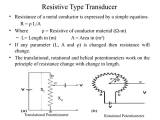
Resistive Type Transducer
•Resistance of a metal conductor is expressed by a simple equation-
R = ρ L/A
• Where ρ = Resistive of conductor material (Ω-m)
– L= Length in (m) A = Area in (m2
)
• If any parameter (L, A and ρ) is changed then resistance will
change.
• The translational, rotational and helical potentiometers work on the
principle of resistance change with change in length.
Translational Potentiometer Rotational Potentiometer
xt
xo
3.
• The outputvoltage under ideal
condition is-
• Vo = [(Resistance at the o/p
terminal) X Input Voltage]/
Resistance at the input terminal
Vo = Xo Vi / Xt
• For rotational potentiometer-
• Vo = Фo Vi /Фt
• Sensitivity = Output/Input
• = Vo/ Vi = Xo / Xt =θo /θt
• The resistivity of metal is changed
with change in temperature thus
causing change in resistance.
• For translational devices, the
resolution is limited to 25-50μm.
• Variation in resistance is in step
so the resolution is also limited.
• Actual practical limit is 20 to 40
turns per mm.
• For rotational devices, angular
resolution is-
– 3 to 6 degree/D Where D =
Diameter of the
potentiometer
• In order to get high resolution
thin wire should be used and
placed very closely.
• In case for fine resolution and
high resistance, Carbon-film or
a conductive-plastice
resistance elements is used.
• Resolution can be increased by
using multi-turn potentiometer
which is known as helipot or
helical potentiometer.
Helical
Potentiometer
4.
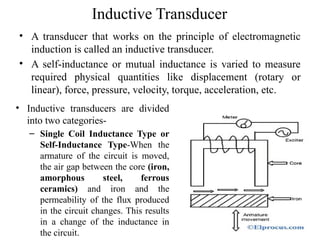
Inductive Transducer
• Atransducer that works on the principle of electromagnetic
induction is called an inductive transducer.
• A self-inductance or mutual inductance is varied to measure
required physical quantities like displacement (rotary or
linear), force, pressure, velocity, torque, acceleration, etc.
• Inductive transducers are divided
into two categories-
– Single Coil Inductance Type or
Self-Inductance Type-When the
armature of the circuit is moved,
the air gap between the core (iron,
amorphous steel, ferrous
ceramics) and iron and the
permeability of the flux produced
in the circuit changes. This results
in a change of the inductance in
the circuit.
5.
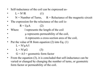
• Self-inductance ofthe coil can be expressed as-
• L = N2
/R (1)
• N = Number of Turns, R = Reluctance of the magnetic circuit
• The expression for the reluctance of the coil is-
• R = l/µA (2)
• Where l represents the length of the coil
• μ represents permeability of the coil,
• A represents a cross-section area of the coil,
• Put the value of R from equation (2) into Eq. (1)
L = N2
µA/l
• L = N2
µG (3)
• G = A/l = geometric form factor
• From the equation (3), it is concluded that self-inductance can be
varied or changed by changing the number of turns, or geometric
form factor or permeability of the coil.
6.
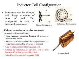
Inductor Coil Configuration
•Inductance can be changed
with change in number of
turns of coil. This
arrangement is used to
measure displacement. Linear displacement
Rotational displacement
• Coil may be used as air cored or iron-cored.
• Air cored coils are preferred-
• High frequency operation because of absence of
eddy-current losses.
• Inductance of air-cored coil is independent of coil
current as permeability of the air is constant.
• Size is large compared to iron cored coil.
• Change in inductance of air core coil is small
because of the low permeability of air.
• It is affected by external magnetic field.
Air-cored coil
7.
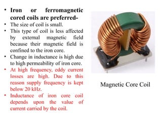
• Iron orferromagnetic
cored coils are preferred-
• The size of coil is small.
• This type of coil is less affected
by external magnetic field
because their magnetic field is
confined to the iron core.
• Change in inductance is high due
to high permeability of iron core.
• At high frequency, eddy current
losses are high. Due to this
reason supply frequency is kept
below 20 kHz.
• Inductance of iron core coil
depends upon the value of
current carried by the coil.
Magnetic Core Coil
8.
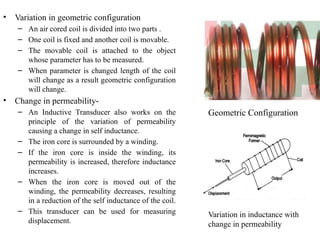
• Variation ingeometric configuration
– An air cored coil is divided into two parts .
– One coil is fixed and another coil is movable.
– The movable coil is attached to the object
whose parameter has to be measured.
– When parameter is changed length of the coil
will change as a result geometric configuration
will change.
• Change in permeability-
– An Inductive Transducer also works on the
principle of the variation of permeability
causing a change in self inductance.
– The iron core is surrounded by a winding.
– If the iron core is inside the winding, its
permeability is increased, therefore inductance
increases.
– When the iron core is moved out of the
winding, the permeability decreases, resulting
in a reduction of the self inductance of the coil.
– This transducer can be used for measuring
displacement.
Geometric Configuration
Variation in inductance with
change in permeability
9.
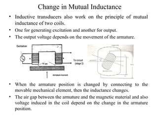
Change in MutualInductance
• Inductive transducers also work on the principle of mutual
inductance of two coils.
• One for generating excitation and another for output.
• The output voltage depends on the movement of the armature.
• When the armature position is changed by connecting to the
movable mechanical element, then the inductance changes.
• The air gap between the armature and the magnetic material and also
voltage induced in the coil depend on the change in the armature
position.
10.
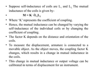
• Suppose self-inductanceof coils are L1 and L2, The mutual
inductance of the coils is given by-
• M = K √L1L2
• Where ‘K’ represents the coefficient of coupling.
• Hence, the mutual inductance can be changed by varying the
self-inductance of the individual coils or by changing the
coefficient of coupling.
• The factor K depends on the distance and orientation of the
coils.
• To measure the displacement, armature is connected to a
movable object. As the object moves, the coupling factor K
changes, which results in a change in mutual inductance in
the coils.
• This change in mutual inductance or output voltage can be
calibrated in terms of displacement for an instrument.
11.
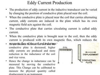
Eddy Current Production
•The production of eddy current in the inductive transducer can be varied
by changing the position of conductive plate placed near the coil.
• When the conductive plate is placed near the coil that carries alternating
current, eddy currents are induced in the plate which has its own
magnetic field acts against the coil.
• The conductive plate that carries circulating current is called eddy
current.
• When the conductive plate is brought near to the coil, then the eddy
current is produced with its own magnetic flux, which reduces the
magnetic flux of the coil and inductance.
• As the distance between the coil and the
conductive plate is decreased, higher
eddy currents are produced and more
reduction in the inductance of the coil
and vice versa.
• Hence the change in inductance can be
measured by moving the conductive
plate. This Change can be calibrated to
measure the physical quantity called
12.
Capacitive Transducer
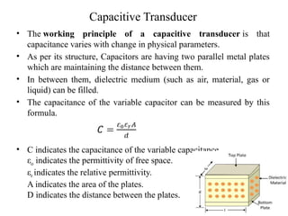
• Theworking principle of a capacitive transducer is that
capacitance varies with change in physical parameters.
• As per its structure, Capacitors are having two parallel metal plates
which are maintaining the distance between them.
• In between them, dielectric medium (such as air, material, gas or
liquid) can be filled.
• The capacitance of the variable capacitor can be measured by this
formula.
• C indicates the capacitance of the variable capacitance.
εo indicates the permittivity of free space.
εr indicates the relative permittivity.
A indicates the area of the plates.
D indicates the distance between the plates.
13.
• It isa passive type of transducer means external power is
required for operation.
• The capacitive transducer works on the principle of change
of capacitance which may be caused by-
– Change in overlapping area.
– Change in the distance between the plates
– Change in dielectric constant.
• These changes (Change in overlapping area and distance
between the plates) are caused by physical variable like
displacement, force and pressure.
• The change in capacitance with change in dielectric constant
causes in measurement of liquid and gas level.
• The capacitance of transducer is measured with the Schering
bridge.
• The output impedance of transducer is given by-
Xc = 1/2 f C
ᴫ
14.
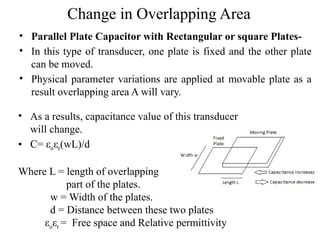
Change in OverlappingArea
• Parallel Plate Capacitor with Rectangular or square Plates-
• In this type of transducer, one plate is fixed and the other plate
can be moved.
• Physical parameter variations are applied at movable plate as a
result overlapping area A will vary.
• As a results, capacitance value of this transducer
will change.
• C= εoεr(wL)/d
Where L = length of overlapping
part of the plates.
w = Width of the plates.
d = Distance between these two plates
εoεr = Free space and Relative permittivity
15.
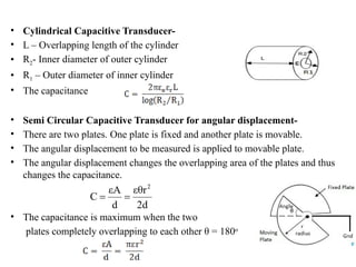
• Cylindrical CapacitiveTransducer-
• L – Overlapping length of the cylinder
• R2- Inner diameter of outer cylinder
• R1 – Outer diameter of inner cylinder
• The capacitance
• Semi Circular Capacitive Transducer for angular displacement-
• There are two plates. One plate is fixed and another plate is movable.
• The angular displacement to be measured is applied to movable plate.
• The angular displacement changes the overlapping area of the plates and thus
changes the capacitance.
• The capacitance is maximum when the two
plates completely overlapping to each other θ = 180o
16.
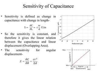
Sensitivity of Capacitance
•Sensitivity is defined as change in
capacitance with change in length-
• So the sensitivity is constant, and
therefore it gives the linear relation
between the capacitance and linear
displacement (Overlapping Area).
• The sensitivity for angular
displacement-
Max.
17.
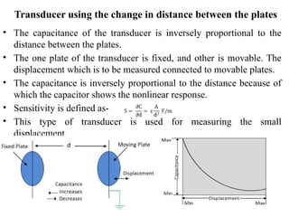
• The capacitanceof the transducer is inversely proportional to the
distance between the plates.
• The one plate of the transducer is fixed, and other is movable. The
displacement which is to be measured connected to movable plates.
• The capacitance is inversely proportional to the distance because of
which the capacitor shows the nonlinear response.
• Sensitivity is defined as-
• This type of transducer is used for measuring the small
displacement.
Transducer using the change in distance between the plates
18.
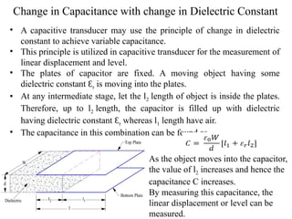
Change in Capacitancewith change in Dielectric Constant
• A capacitive transducer may use the principle of change in dielectric
constant to achieve variable capacitance.
• This principle is utilized in capacitive transducer for the measurement of
linear displacement and level.
• The plates of capacitor are fixed. A moving object having some
dielectric constant Ɛr is moving into the plates.
• At any intermediate stage, let the l2 length of object is inside the plates.
Therefore, up to l2 length, the capacitor is filled up with dielectric
having dielectric constant Ɛr whereas l1 length have air.
• The capacitance in this combination can be found as-
As the object moves into the capacitor,
the value of l2 increases and hence the
capacitance C increases.
By measuring this capacitance, the
linear displacement or level can be
measured.
19.
Advantages and Disadvantagesof
Capacitive Transducer
• It is very sensitive transducer.
• It has high input impedance so loading effect is less.
• It requires very small power for operation.
• It gives good frequency response because of which
it can be used for dynamic study.
• Metallic parts of the transducer require insulation.
• Some transducer shows nonlinear characteristics so
operation is in limited range.
• Proper earthling is required to reduce the effect of
stray magnetic field.
20.
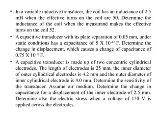
• In avariable inductive transducer, the coil has an inductance of 2.5
mH when the effective turns on the coil are 50. Determine the
inductance of the coil when the measurand makes the effective
turns on the coil 52.
• A capacitive transducer with its plate separation of 0.05 mm, under
static conditions has a capacitance of 5 X 10-12
F. Determine the
change in displacement, which causes a change of capacitance of
0.75 X 10⁻¹²
F.
• A capacitive transducer is made up of two concentric cylindrical
electrodes. The length of electrodes is 25 mm, the inner diameter
of outer cylindrical electrodes is 4.2 mm and the outer diameter of
inner cylindrical electrode is 4.0 mm. Determine the sensitivity of
the transducer. Assume air medium. Determine the change in
capacitance for a displacement of the inner electrode of 2.5 mm.
Determine also the electric stress when a voltage of 150 V is
applied across the electrodes.
21.
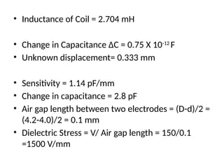
• Inductance ofCoil = 2.704 mH
• Change in Capacitance ∆C = 0.75 X 10⁻¹²
F
• Unknown displacement= 0.333 mm
• Sensitivity = 1.14 pF/mm
• Change in capacitance = 2.8 pF
• Air gap length between two electrodes = (D-d)/2 =
(4.2-4.0)/2 = 0.1 mm
• Dielectric Stress = V/ Air gap length = 150/0.1
=1500 V/mm

![• The output voltage under ideal
condition is-
• Vo = [(Resistance at the o/p
terminal) X Input Voltage]/
Resistance at the input terminal
Vo = Xo Vi / Xt
• For rotational potentiometer-
• Vo = Фo Vi /Фt
• Sensitivity = Output/Input
• = Vo/ Vi = Xo / Xt =θo /θt
• The resistivity of metal is changed
with change in temperature thus
causing change in resistance.
• For translational devices, the
resolution is limited to 25-50μm.
• Variation in resistance is in step
so the resolution is also limited.
• Actual practical limit is 20 to 40
turns per mm.
• For rotational devices, angular
resolution is-
– 3 to 6 degree/D Where D =
Diameter of the
potentiometer
• In order to get high resolution
thin wire should be used and
placed very closely.
• In case for fine resolution and
high resistance, Carbon-film or
a conductive-plastice
resistance elements is used.
• Resolution can be increased by
using multi-turn potentiometer
which is known as helipot or
helical potentiometer.
Helical
Potentiometer](https://image.slidesharecdn.com/resistiveinductiveandcapacitivetransducer-250629173351-f30d57a3/85/Resistive-inductive-and-Capacitive-Transducer-pptx-3-320.jpg)