Download to read offline
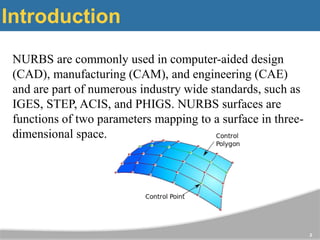

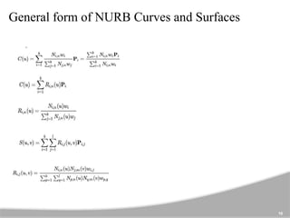


NURBS (Non-Uniform Rational B-Splines) are mathematical models used in CAD, CAM, and CAE for generating and representing curves and surfaces with complex shapes. They differ from polygons in that they are patch-based and composed of curves rather than straight lines, allowing for more flexibility in design. NURBS offer several advantages, including reduced memory consumption, quick evaluation, and the ability to accurately represent both standard and free-form shapes.