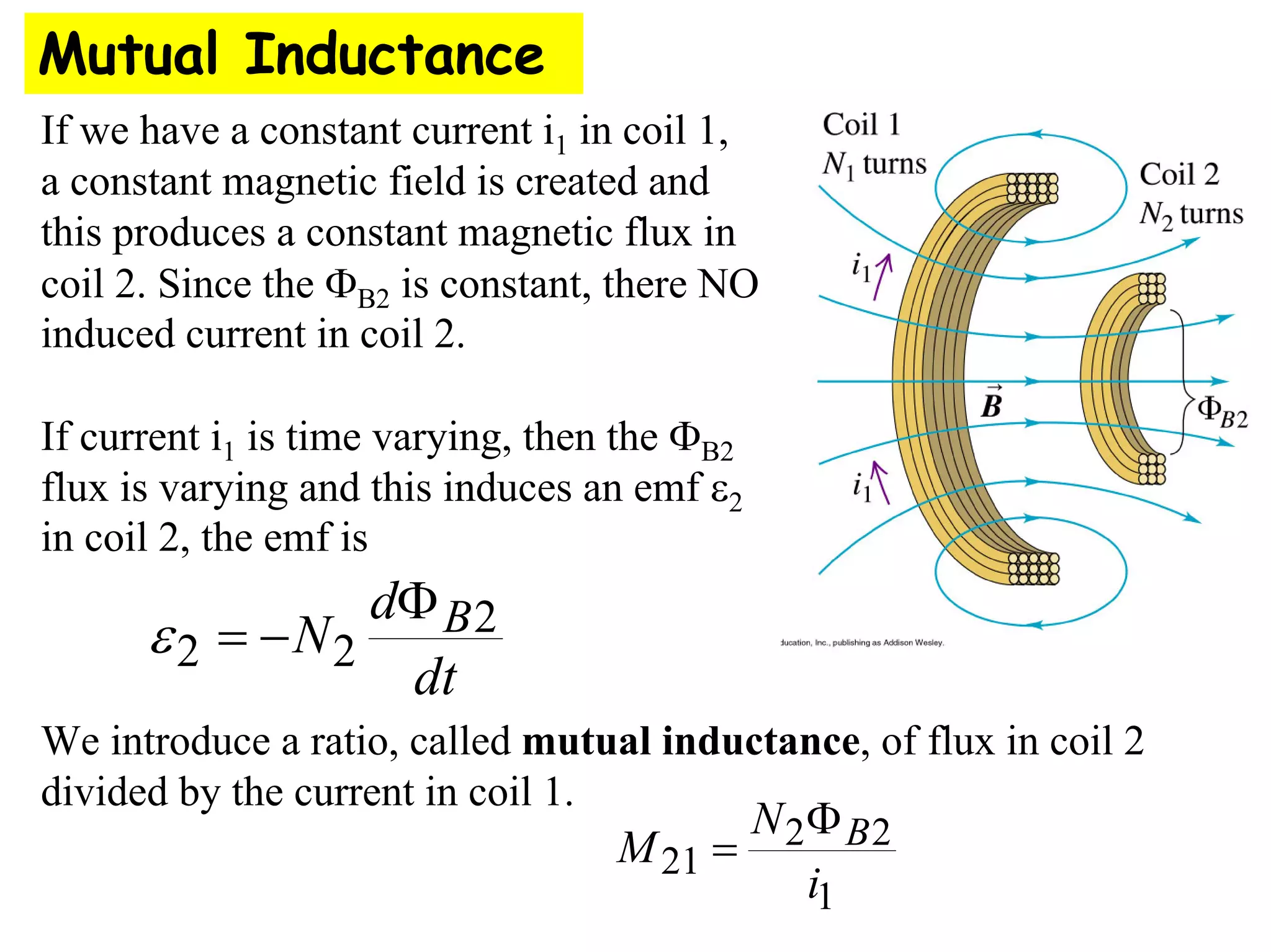
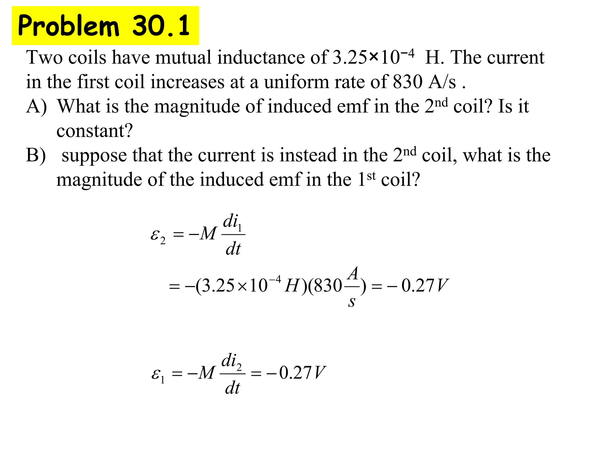
Mutual Inductance
If we have a constant current i1 in coil 1,
a constant magnetic field is created and
this produces a constant magnetic flux in
coil 2. Since the ΦB2 is constant, there NO
induced current in coil 2.
If current i1 is time varying, then the ΦB2
flux is varying and this induces an emf ε2
in coil 2, the emf is
We introduce a ratio, called mutual inductance, of flux in coil 2
divided by the current in coil 1.
dt
d
N B2
2
2
Φ
−
=
ε
1
2
2
21
i
N
M B
Φ
=
Mutual Inductance
mutual inductance, , can now be used in Faraday’s eqn
We can also the varying current i2 which creates a changing flux ΦB1
in coil 1 and induces an emf ε1. This is given by a similar eqn.
1
2
2
21
i
N
M B
Φ
=
dt
di
M
dt
d
N
dt
di
M B 1
21
2
2
2
2
1
21 ; −
=
−
=
Φ
= ε
ε
dt
di
M 2
12
1 −
=
ε
It can be shown (we do not prove here) that,
The units of mutual inductance is T ⋅ m2/A = Weber/A = Henry
M
M
M =
= 21
12
(after the Joseph Henry, who missed Faraday’s Law)
2
2
1
21 B
N
i
M Φ
=
The induced emf,
has the following features;
Mutual Inductance
dt
di
M 2
1 −
=
ε
• The induced emf opposes the magnetic flux change
• The induced emf increases if the currents changes very
fast
• The induced emf depends on M, which depends only the
geometry of the two coils and not the current.
• For a few simple cases, we can calculate M, but usually it
is just measured.
Two coils have mutual inductance of 3.25×10⁻⁴ H. The current
in the first coil increases at a uniform rate of 830 A/s .
A) What is the magnitude of induced emf in the 2nd coil? Is it
constant?
B) suppose that the current is instead in the 2nd coil, what is the
magnitude of the induced emf in the 1st coil?
Problem 30.1
V
s
A
H
dt
di
M
27
.
0
)
830
)(
10
25
.
3
( 4
1
2
−
=
×
−
=
−
=
−
ε
V
dt
di
M 27
.
0
2
1 −
=
−
=
ε
Magnetic field due to coil 1 is
B1 = μ0n1i1 = μ0N1i1 / l
Mutual inductance is,
l
A
N
N
l
i
A
i
N
N
i
A
B
N
i
N
M B
2
1
0
1
1
1
0
2
1
1
2
1
2
2
μ
μ
=
=
=
Φ
=
The induced emf in coil1 from coil2 is
dt
di
l
A
N
N
dt
di
M 2
2
1
0
2
1
μ
ε −
=
−
=
Tesla Coil Example
Nicolai Tesla (1856-1943)
Born in Croatia, graduated from University of
Prague. Arrived in New York with 4cents and went
to work for Edison. Tesla invented polyphase
alternating-current system, induction motor,
alternating-current power transmission, Tesla
coil transformer, wireless communication, radio,
and fluorescent lights. He set up a Tesla coil in
Colorado Springs in 1899, below
is a photo of this lab. He lighted
lamps 40Km away. He also claimed
to receive messages from another
planet!! In honor of his contributions
to electromagnetic phenomena, the
Magnetic field intensity was named
in units of “Tesla”
Applications of Mutual Inductance
• Transformers
– Change one AC voltage into another ε
(primary) (secondary)
∼
N2
N1
iron
V2
V1
2
2 1
1
N
V V
N
=
• Airport Metal Detectors
– Pulsed current Æ pulsed magnetic field
Æ Induces emf in metal
– Ferromagnetic metals “draw in” more B
Æ larger mutual inductance Æ larger emf
– Emf Æ current (how much, how long it
lasts, depends on the resistivity of the
material)
– Decaying current produces decaying
magnetic field
Æ induces current in receiver coils
– Magnitude & duration of signal depends
on the composition and geometry of the
metal object.
Applications of Mutual Inductance
• Pacemakers
– It’s not easy to change the battery!
– Instead, use an external AC supply.
~
– Alternating current
Æ alternating B
Æ alternating ФB inside “wearer”
Æ induces AC current to power
pacemaker
Applications of Mutual Inductance
Self Inductance
We previously considered induction between 2 coils. Now we consider
the situation where a single isolated coil induces emf on itself. This is
Called “back emf” and if the current changes, there is a self induced emf
that opposes the change in current. We form the same ratio, now called
Self-Inductance, L,
and we have the back emf,
i
N
L B
Φ
=
dt
di
L
−
=
ε
Behavior of isolated coil in circuits
Resistor with current I
has potential drop, V=iR
from a to b
Coil with
a) constant current i has NO
Voltage drop
b) di/dt>0, potential decreases
from a to b, V=Ldi/dt
c) di/dt<0, potential increases
from a to b, V=-L|di/dt|
+
+
- -
Remember, emf in coil opposes current change.
Self inductance of long solenoid
l
r
N turns
• Long Solenoid:
N turns total, radius r, Length l
I
l
N
B
l
r 0
μ
=
⇒
<<
For a single turn, 2
0
2
r
I
l
N
BA
r
A π
μ
φ
π =
=
⇒
=
The flux through a turn is given by:
2
0 r
I
l
N
B π
μ
=
Φ
Inductance of solenoid can then be calculated as:
2
2
0
2
2
0 r
l
l
N
r
l
N
I
N
L B
π
μ
π
μ ⎟
⎠
⎞
⎜
⎝
⎛
=
=
Φ
≡
Lecture 17, Act 1
• Consider the two inductors shown:
– Inductor 1 has length l, N total turns
and has inductance L1.
– Inductor 2 has length 2l, 2N total turns
and has inductance L2.
– What is the relation between L1 and
L2?
(a) L2 < L1 (b) L2 = L1 (c) L2 > L1
l
r
N turns
r
2l
r
2N turns
Lecture 17, Act 1
(a) L2 < L1 (b) L2 = L1 (c) L2 > L1
• To determine the self-inductance L, we need to determine the flux ΦB
which passes through the coils when a current I flows: L ≡ NΦB / I.
• To calculate the flux, we first need to calculate the magnetic field B
produced by the current: B = μ0(N/l)I
• i.e., the B field is proportional to the number of turns per unit
length.
• Therefore, B1 = B2. But does that mean L1 = L2?
l
r
N turns
r
2l
r
2N turns
• Consider the two inductors shown:
– Inductor 1 has length l, N total turns
and has inductance L1.
– Inductor 2 has length 2l, 2N total turns
and has inductance L2.
– What is the relation between L1 and
L2?
Lecture 17, Act 1
l
r
N turns
r
2l
r
2N turns
• To calculate L, we need to calculate the
flux.
• Since B1=B2, the flux through any
given turn is the same in each
inductor
• There are twice as many turns in inductor 2; therefore the net flux
through inductor 2 is twice the flux through inductor 1! Therefore,
L2 = 2L1.
Inductors in series add (like resistors): eff 1 2
L L L
= +
And inductors in parallel
add like resistors in parallel: eff 1 2
1 1 1
L L L
= +
Self Inductance of toroidal solenoid
The magnetic field in a toroid was
and the net mag. flux is
Hence the self inductance is,
A
r
N
A
r
i
Ni
N
i
N
L B
π
μ
π
μ
2
2
0
2
0 =
=
Φ
=
r
Ni
B
π
μ
2
0
=
A
r
Ni
BA
B
π
μ
2
0
=
=
Φ
Example: N = 200, A = 5 cm2, r = 0.1 m
H
H
x
m
m
L μ
π
π
40
10
4
)
10
5
(
)
1
.
0
(
2
10
4
200 5
2
4
7
2
=
=
×
×
= −
−
−
Approximates B
as value at
center of coil.

fall2010-28 (1).pdf

  • 1.
    Mutual Inductance If wehave a constant current i1 in coil 1, a constant magnetic field is created and this produces a constant magnetic flux in coil 2. Since the ΦB2 is constant, there NO induced current in coil 2. If current i1 is time varying, then the ΦB2 flux is varying and this induces an emf ε2 in coil 2, the emf is We introduce a ratio, called mutual inductance, of flux in coil 2 divided by the current in coil 1. dt d N B2 2 2 Φ − = ε 1 2 2 21 i N M B Φ =
  • 2.
    Mutual Inductance mutual inductance,, can now be used in Faraday’s eqn We can also the varying current i2 which creates a changing flux ΦB1 in coil 1 and induces an emf ε1. This is given by a similar eqn. 1 2 2 21 i N M B Φ = dt di M dt d N dt di M B 1 21 2 2 2 2 1 21 ; − = − = Φ = ε ε dt di M 2 12 1 − = ε It can be shown (we do not prove here) that, The units of mutual inductance is T ⋅ m2/A = Weber/A = Henry M M M = = 21 12 (after the Joseph Henry, who missed Faraday’s Law) 2 2 1 21 B N i M Φ =
  • 3.
    The induced emf, hasthe following features; Mutual Inductance dt di M 2 1 − = ε • The induced emf opposes the magnetic flux change • The induced emf increases if the currents changes very fast • The induced emf depends on M, which depends only the geometry of the two coils and not the current. • For a few simple cases, we can calculate M, but usually it is just measured.
  • 4.
    Two coils havemutual inductance of 3.25×10⁻⁴ H. The current in the first coil increases at a uniform rate of 830 A/s . A) What is the magnitude of induced emf in the 2nd coil? Is it constant? B) suppose that the current is instead in the 2nd coil, what is the magnitude of the induced emf in the 1st coil? Problem 30.1 V s A H dt di M 27 . 0 ) 830 )( 10 25 . 3 ( 4 1 2 − = × − = − = − ε V dt di M 27 . 0 2 1 − = − = ε
  • 5.
    Magnetic field dueto coil 1 is B1 = μ0n1i1 = μ0N1i1 / l Mutual inductance is, l A N N l i A i N N i A B N i N M B 2 1 0 1 1 1 0 2 1 1 2 1 2 2 μ μ = = = Φ = The induced emf in coil1 from coil2 is dt di l A N N dt di M 2 2 1 0 2 1 μ ε − = − = Tesla Coil Example
  • 6.
    Nicolai Tesla (1856-1943) Bornin Croatia, graduated from University of Prague. Arrived in New York with 4cents and went to work for Edison. Tesla invented polyphase alternating-current system, induction motor, alternating-current power transmission, Tesla coil transformer, wireless communication, radio, and fluorescent lights. He set up a Tesla coil in Colorado Springs in 1899, below is a photo of this lab. He lighted lamps 40Km away. He also claimed to receive messages from another planet!! In honor of his contributions to electromagnetic phenomena, the Magnetic field intensity was named in units of “Tesla”
  • 7.
    Applications of MutualInductance • Transformers – Change one AC voltage into another ε (primary) (secondary) ∼ N2 N1 iron V2 V1 2 2 1 1 N V V N = • Airport Metal Detectors – Pulsed current Æ pulsed magnetic field Æ Induces emf in metal – Ferromagnetic metals “draw in” more B Æ larger mutual inductance Æ larger emf – Emf Æ current (how much, how long it lasts, depends on the resistivity of the material) – Decaying current produces decaying magnetic field Æ induces current in receiver coils – Magnitude & duration of signal depends on the composition and geometry of the metal object.
  • 8.
    Applications of MutualInductance • Pacemakers – It’s not easy to change the battery! – Instead, use an external AC supply. ~ – Alternating current Æ alternating B Æ alternating ФB inside “wearer” Æ induces AC current to power pacemaker
  • 9.
  • 10.
    Self Inductance We previouslyconsidered induction between 2 coils. Now we consider the situation where a single isolated coil induces emf on itself. This is Called “back emf” and if the current changes, there is a self induced emf that opposes the change in current. We form the same ratio, now called Self-Inductance, L, and we have the back emf, i N L B Φ = dt di L − = ε
  • 11.
    Behavior of isolatedcoil in circuits Resistor with current I has potential drop, V=iR from a to b Coil with a) constant current i has NO Voltage drop b) di/dt>0, potential decreases from a to b, V=Ldi/dt c) di/dt<0, potential increases from a to b, V=-L|di/dt| + + - - Remember, emf in coil opposes current change.
  • 12.
    Self inductance oflong solenoid l r N turns • Long Solenoid: N turns total, radius r, Length l I l N B l r 0 μ = ⇒ << For a single turn, 2 0 2 r I l N BA r A π μ φ π = = ⇒ = The flux through a turn is given by: 2 0 r I l N B π μ = Φ Inductance of solenoid can then be calculated as: 2 2 0 2 2 0 r l l N r l N I N L B π μ π μ ⎟ ⎠ ⎞ ⎜ ⎝ ⎛ = = Φ ≡
  • 13.
    Lecture 17, Act1 • Consider the two inductors shown: – Inductor 1 has length l, N total turns and has inductance L1. – Inductor 2 has length 2l, 2N total turns and has inductance L2. – What is the relation between L1 and L2? (a) L2 < L1 (b) L2 = L1 (c) L2 > L1 l r N turns r 2l r 2N turns
  • 14.
    Lecture 17, Act1 (a) L2 < L1 (b) L2 = L1 (c) L2 > L1 • To determine the self-inductance L, we need to determine the flux ΦB which passes through the coils when a current I flows: L ≡ NΦB / I. • To calculate the flux, we first need to calculate the magnetic field B produced by the current: B = μ0(N/l)I • i.e., the B field is proportional to the number of turns per unit length. • Therefore, B1 = B2. But does that mean L1 = L2? l r N turns r 2l r 2N turns • Consider the two inductors shown: – Inductor 1 has length l, N total turns and has inductance L1. – Inductor 2 has length 2l, 2N total turns and has inductance L2. – What is the relation between L1 and L2?
  • 15.
    Lecture 17, Act1 l r N turns r 2l r 2N turns • To calculate L, we need to calculate the flux. • Since B1=B2, the flux through any given turn is the same in each inductor • There are twice as many turns in inductor 2; therefore the net flux through inductor 2 is twice the flux through inductor 1! Therefore, L2 = 2L1. Inductors in series add (like resistors): eff 1 2 L L L = + And inductors in parallel add like resistors in parallel: eff 1 2 1 1 1 L L L = +
  • 16.
    Self Inductance oftoroidal solenoid The magnetic field in a toroid was and the net mag. flux is Hence the self inductance is, A r N A r i Ni N i N L B π μ π μ 2 2 0 2 0 = = Φ = r Ni B π μ 2 0 = A r Ni BA B π μ 2 0 = = Φ Example: N = 200, A = 5 cm2, r = 0.1 m H H x m m L μ π π 40 10 4 ) 10 5 ( ) 1 . 0 ( 2 10 4 200 5 2 4 7 2 = = × × = − − − Approximates B as value at center of coil.