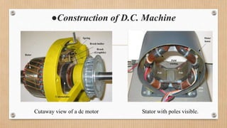
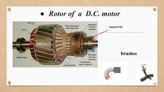
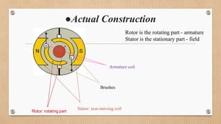
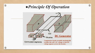
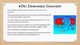
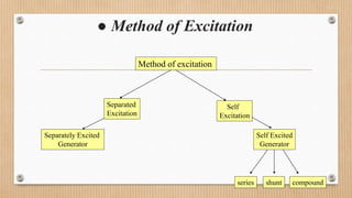
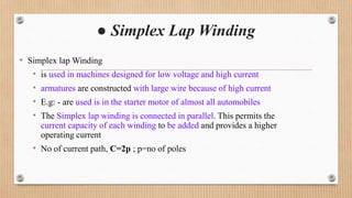
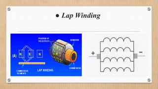
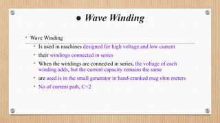
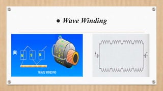
KALOL INSTITUTE OF TECHNOLOGY& RESEARCH CENTER
PRESENTATION ON D.C. MACHINES
Subject:-D.C. machine & Transformer
Enrollment No:-130260109039
Topics to be covered……
•Construction of D.C. Machine
•Working Principle of D.C Machine(Generator)
•Method of Excitation
•Armature Winding:-
Introduction of Simplex lap & Wave Windings
●Construction of D.C. Machine
Cutaway view of a dc motor Stator with poles visible.
● Rotor of a D.C. motor
segments
brushes
●Actual Construction
Stator: non-moving coil
Brushes
Armature coil
Rotor is the rotating part - armature
Stator is the stationary part - field
●Working principle of D.C. Machine
• Whenever a conductor is moved within a magnetic field in such a way
that the conductor cuts across magnetic lines of flux, voltage is
generated in the conductor.
• The AMOUNT of voltage generated depends on:
i. the strength of the magnetic field,
ii. the angle at which the conductor cuts the magnetic field,
iii.the speed at which the conductor is moved, and
iv. the length of the conductor within the magnetic field
●Principle Of Operation
●The Elementary Generator
• The simplest elementary generator that can be built is an ac
generator.
• Basic generating principles are most easily explained through the
use of the elementary ac generator.
• For this reason, the ac generator will be discussed first. The dc
generator will be discussed later.
• An elementary generator consists of a wire loop mounted on the
shaft, so that it can be rotated in a stationary magnetic field.
• This will produce an induced e.m.f in the loop.
• Sliding contacts (brushes) connect the loop to an external circuit
load in order to pick up or use the induced e.m.f.
●Observe
• The meter direction
• The conductors of the armature loop
• Direction of the current flow
● Method of Excitation
Method of excitation
Separated
Excitation
Self
Excitation
Separately Excited
Generator
Self Excited
Generator
series shunt compound
● Separately Excited Generator
• When the field winding is supplied from external, separated
d.c. supply i.e. excitation of field winding is separate then the
generator is called separately excited generator.
• The field winding of this type of generator has large number
of turns of thin wire.
• So, length of such winding is more with less cross-sectional
area.
● Circuit diagram of Separately excited generator
● Self Excited Generator
• When the field winding is supplied from the generator of the
generator itself then it is said to be self excited generator.
• In self excited generator the e.m.f. is produced by residual flux.
• Thus, when the generator is started, due to such residual flux , it
develops a small e.m.f. which now drives a small current through
the field winding.
● Circuit diagram of self excited generator
● Machine Windings
Winding
armature field
Wave
C=2
Lap
C=2p
Frogleg
Self excited Separately
Excited
series shunt compound
● Armature Windings
• Two types of Armature Windings can be classified in
this p.p.t. or (section)
• 1) Simplex Lap Winding
• 2) Wave Winding
● Simplex Lap Winding
• Simplex lap Winding
• is used in machines designed for low voltage and high current
• armatures are constructed with large wire because of high current
• E.g: - are used is in the starter motor of almost all automobiles
• The Simplex lap winding is connected in parallel. This permits the
current capacity of each winding to be added and provides a higher
operating current
• No of current path, C=2p ; p=no of poles
● Lap Winding
● Wave Winding
• Wave Winding
• Is used in machines designed for high voltage and low current
• their windings connected in series
• When the windings are connected in series, the voltage of each
winding adds, but the current capacity remains the same
• are used is in the small generator in hand-cranked meg ohm meters
• No of current path, C=2
● Wave Winding
D.c. machine

D.c. machine

  • 1.
    KALOL INSTITUTE OFTECHNOLOGY& RESEARCH CENTER PRESENTATION ON D.C. MACHINES Subject:-D.C. machine & Transformer Enrollment No:-130260109039
  • 2.
    Topics to becovered…… •Construction of D.C. Machine •Working Principle of D.C Machine(Generator) •Method of Excitation •Armature Winding:- Introduction of Simplex lap & Wave Windings
  • 3.
    ●Construction of D.C.Machine Cutaway view of a dc motor Stator with poles visible.
  • 4.
    ● Rotor ofa D.C. motor segments brushes
  • 5.
    ●Actual Construction Stator: non-movingcoil Brushes Armature coil Rotor is the rotating part - armature Stator is the stationary part - field
  • 6.
    ●Working principle ofD.C. Machine • Whenever a conductor is moved within a magnetic field in such a way that the conductor cuts across magnetic lines of flux, voltage is generated in the conductor. • The AMOUNT of voltage generated depends on: i. the strength of the magnetic field, ii. the angle at which the conductor cuts the magnetic field, iii.the speed at which the conductor is moved, and iv. the length of the conductor within the magnetic field
  • 7.
  • 8.
    ●The Elementary Generator •The simplest elementary generator that can be built is an ac generator. • Basic generating principles are most easily explained through the use of the elementary ac generator. • For this reason, the ac generator will be discussed first. The dc generator will be discussed later. • An elementary generator consists of a wire loop mounted on the shaft, so that it can be rotated in a stationary magnetic field. • This will produce an induced e.m.f in the loop. • Sliding contacts (brushes) connect the loop to an external circuit load in order to pick up or use the induced e.m.f.
  • 9.
    ●Observe • The meterdirection • The conductors of the armature loop • Direction of the current flow
  • 10.
    ● Method ofExcitation Method of excitation Separated Excitation Self Excitation Separately Excited Generator Self Excited Generator series shunt compound
  • 11.
    ● Separately ExcitedGenerator • When the field winding is supplied from external, separated d.c. supply i.e. excitation of field winding is separate then the generator is called separately excited generator. • The field winding of this type of generator has large number of turns of thin wire. • So, length of such winding is more with less cross-sectional area.
  • 12.
    ● Circuit diagramof Separately excited generator
  • 13.
    ● Self ExcitedGenerator • When the field winding is supplied from the generator of the generator itself then it is said to be self excited generator. • In self excited generator the e.m.f. is produced by residual flux. • Thus, when the generator is started, due to such residual flux , it develops a small e.m.f. which now drives a small current through the field winding.
  • 14.
    ● Circuit diagramof self excited generator
  • 15.
    ● Machine Windings Winding armaturefield Wave C=2 Lap C=2p Frogleg Self excited Separately Excited series shunt compound
  • 16.
    ● Armature Windings •Two types of Armature Windings can be classified in this p.p.t. or (section) • 1) Simplex Lap Winding • 2) Wave Winding
  • 17.
    ● Simplex LapWinding • Simplex lap Winding • is used in machines designed for low voltage and high current • armatures are constructed with large wire because of high current • E.g: - are used is in the starter motor of almost all automobiles • The Simplex lap winding is connected in parallel. This permits the current capacity of each winding to be added and provides a higher operating current • No of current path, C=2p ; p=no of poles
  • 18.
  • 19.
    ● Wave Winding •Wave Winding • Is used in machines designed for high voltage and low current • their windings connected in series • When the windings are connected in series, the voltage of each winding adds, but the current capacity remains the same • are used is in the small generator in hand-cranked meg ohm meters • No of current path, C=2
  • 20.