This document provides information about fluid dynamics concepts including:
1. Euler's equation of motion which relates velocity and pressure fields for inviscid fluid flow.
2. Bernoulli's equation which relates pressure, velocity, and elevation for steady, incompressible fluid flow without friction.
3. A pilot tube which uses stagnation pressure and static pressure measurements via Bernoulli's equation to determine fluid velocity.
![EDUCATION HOLE PRESENTS
MECHANICS OF
FLUIDS
Module III: Dynamics of Fluid
Flow[Type the document
subtitle]](https://image.slidesharecdn.com/btm305modueiiiedhoe-141001054025-phpapp02/85/Imegate4u-1-320.jpg)
![EDUCATION HOLE PRESENTS
MECHANICS OF
FLUIDS
Module III: Dynamics of Fluid
Flow[Type the document
subtitle]](https://image.slidesharecdn.com/btm305modueiiiedhoe-141001054025-phpapp02/75/Imegate4u-1-2048.jpg)
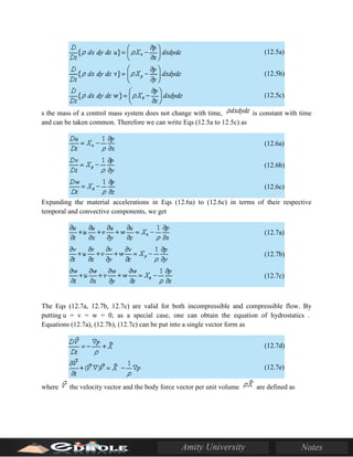
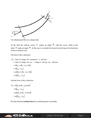
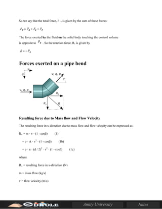
![the streamlines to diverge, and vice versa). If we ignore gravity, then the pressures over the inlet
and outlet areas are constant. Along a streamline on the centerline, the Bernoulli equation and the
one-dimensional continuity equation give, respectively,
These two observations provide an intuitive guide for analyzing fluid flows, even when the flow
is not one-dimensional. For example, when fluid passes over a solid body, the streamlines get
closer together, the flow velocity increases, and the pressure decreases. Airfoils are designed so
that the flow over the top surface is faster than over the bottom surface, and therefore the average
pressure over the top surface is less than the average pressure over the bottom surface, and a
resultant force due to this pressure difference is produced. This is the source of lift on an airfoil.
Lift is defined as the force acting on an airfoil due to its motion, in a direction normal to the
direction of motion. Likewise, drag on an airfoil is defined as the force acting on an airfoil due to
its motion, along the direction of motion.
An easy demonstration of the lift produced by an airstream requires a piece of notebook paper
and two books of about equal thickness. Place the books four to five inches apart, and cover the
gap with the paper. When you blow through the passage made by the books and the paper, what
do you see? Why?
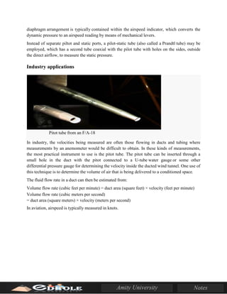
Pilot Tube
A pilot tube is a pressure measurement instrument used to measure fluid flow velocity. The pilot
tube was invented by the French engineer Henri Pilot in the early 18th century[1]
and was
modified to its modern form in the mid-19th century by French scientist Henry Darcy.[2]
It
is widely used to determine the airspeed of an aircraft, water speed of a boat, and to measure
liquid, air and gas velocities in industrial applications. The pitot tube is used to measure the local
velocity at a given point in the flow stream and not the average velocity in the pipe or conduit.[3]
Theory of operation](https://image.slidesharecdn.com/btm305modueiiiedhoe-141001054025-phpapp02/85/Imegate4u-6-320.jpg)


![Welding 2[EDocFind.com]](https://cdn.slidesharecdn.com/ss_thumbnails/cef0456c-72db-4c24-9232-061dfa358ef1-151012162903-lva1-app6892-thumbnail.jpg?width=640&height=640&fit=bounds)


