Downloaded 54 times


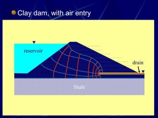
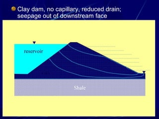
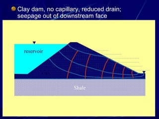


1. The document contains illustrations of various flow nets showing groundwater flow through soils and structures like dams and excavations. 2. Flow nets illustrate groundwater flow under steady state and unsteady state conditions, taking into account factors like soil permeability, capillarity, consolidation, and liquefaction potential. 3. Examples of flow nets show flow through dams made of clay, sand and concrete, as well as flow around excavations supported by sheet piles.

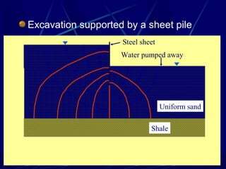
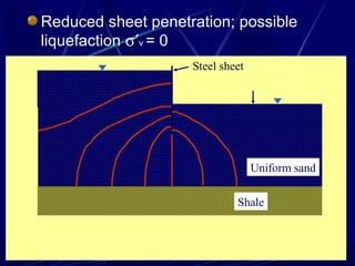
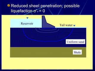
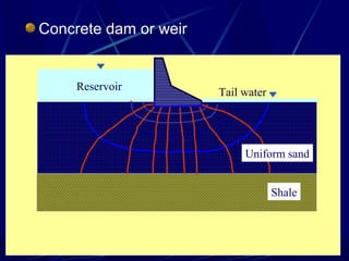
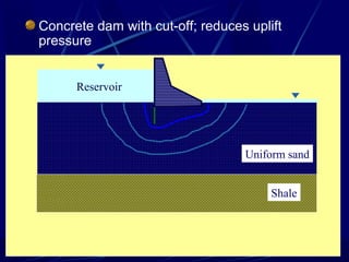
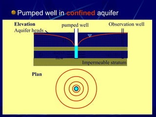
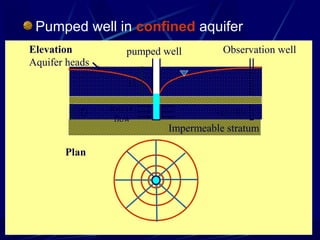
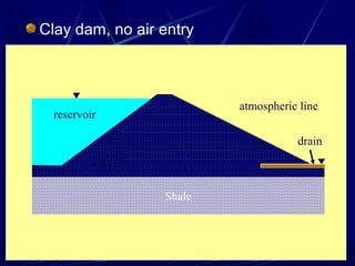
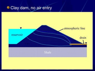
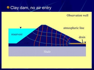
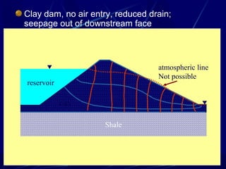
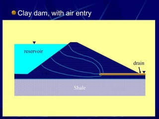
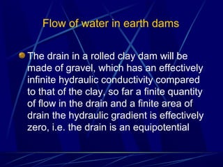
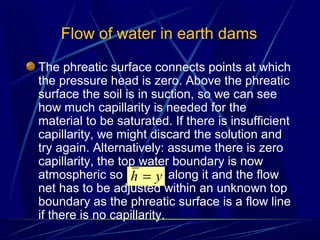
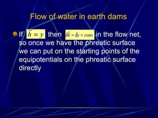
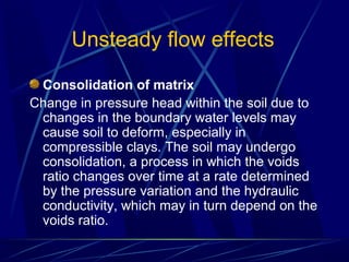
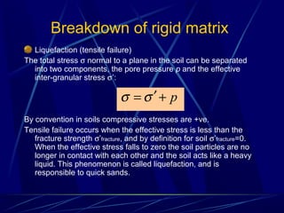
![Geotechnical Engineering-II [Lec #17: Bearing Capacity of Soil]](https://cdn.slidesharecdn.com/ss_thumbnails/17-181123045836-thumbnail.jpg?width=640&height=640&fit=bounds)


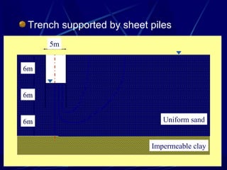
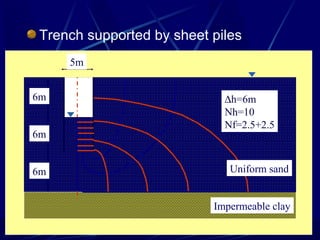
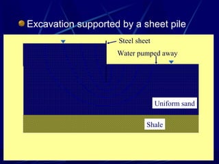
![Geotechnical Engineering-I [Lec #8: Hydrometer Analysis]](https://cdn.slidesharecdn.com/ss_thumbnails/8-180923180849-thumbnail.jpg?width=640&height=640&fit=bounds)


![Geotechnical Engineering-II [Lec #22: Earth Pressure at Rest]](https://cdn.slidesharecdn.com/ss_thumbnails/22-181123050434-thumbnail.jpg?width=640&height=640&fit=bounds)


