Downloaded 1,300 times
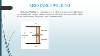

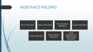
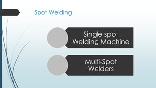
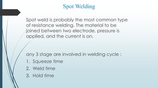


Resistance welding is a welding process that uses heat generated by resistance to electric current passing through the workpieces. There are several types of resistance welding including spot welding, seam welding, projection welding, flash welding, upset welding, percussion welding, and high frequency resistance welding. Spot welding is commonly used in automotive manufacturing to join vehicle body parts and involves applying pressure and electric current between two electrodes to weld metal sheets together.


