Downloaded 477 times

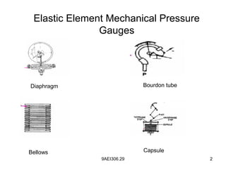
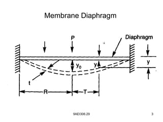
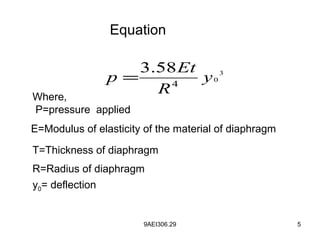
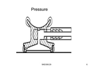


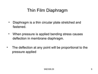
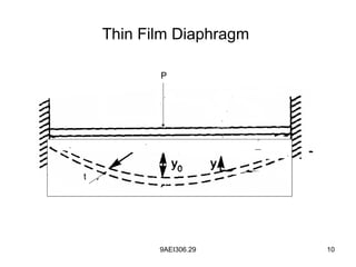
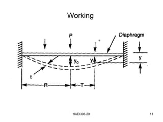
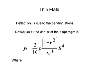
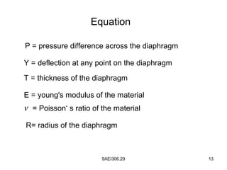


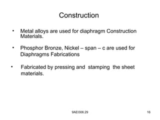
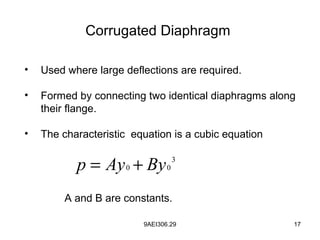

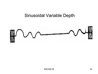
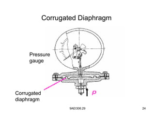

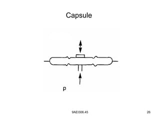
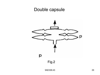

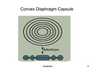
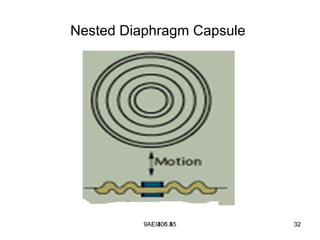
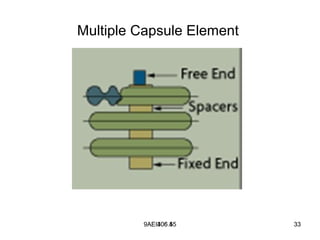


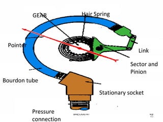
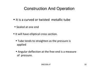
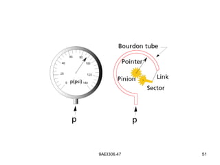
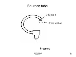
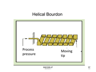
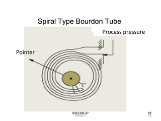
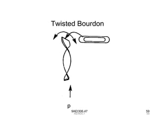
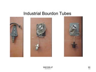
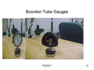
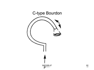
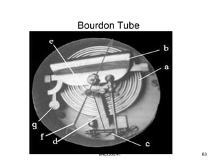
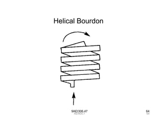


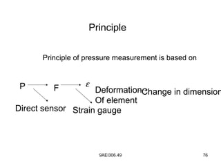
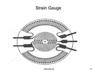
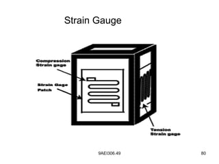
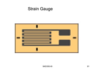
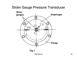
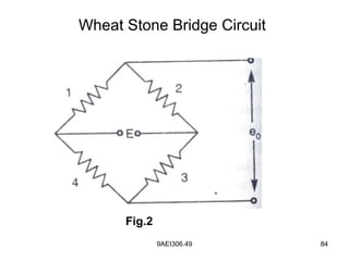
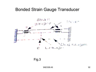
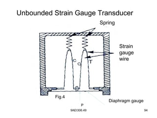

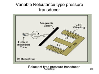
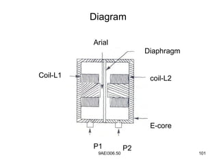
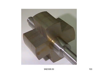

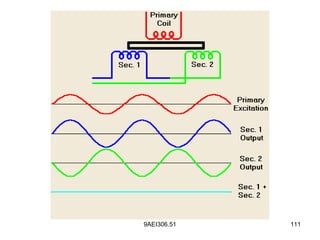


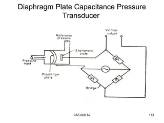
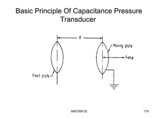

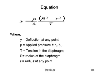

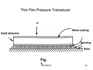
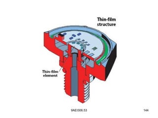


Diaphragm pressure gauges use a thin circular plate that deflects in proportion to applied pressure. Common types include thin film diaphragms, corrugated diaphragms, and capsules which use multiple diaphragms joined together. Bourdon tubes are curved tubes that straighten with pressure to indicate amount. Strain gauge transducers bond strain gauges to a deflecting diaphragm to convert pressure to electrical resistance changes. Variable reluctance transducers use a diaphragm to change the magnetic reluctance in an electromagnetic circuit proportional to pressure.


