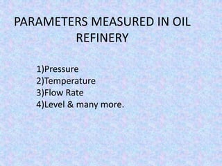
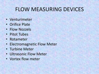
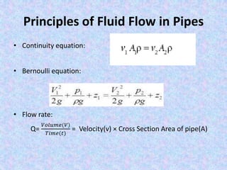
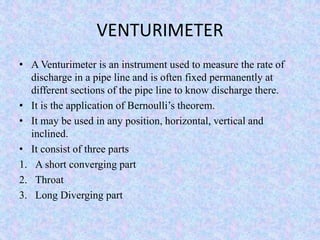
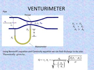
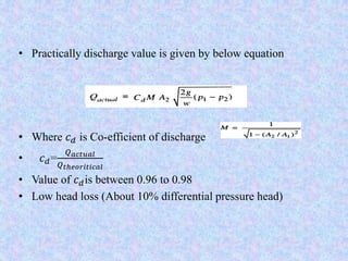
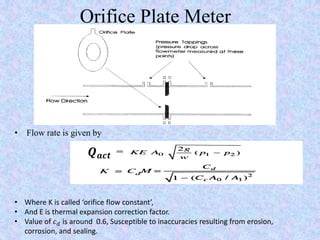
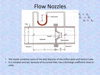
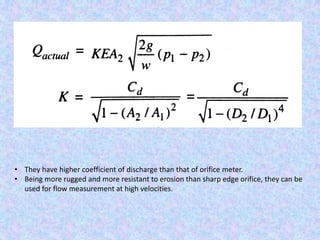
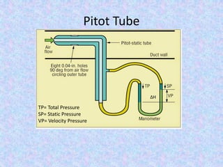
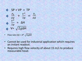
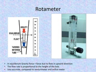
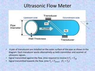
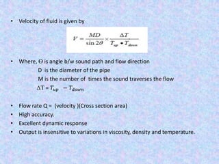
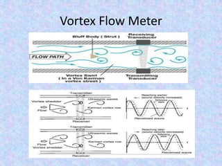
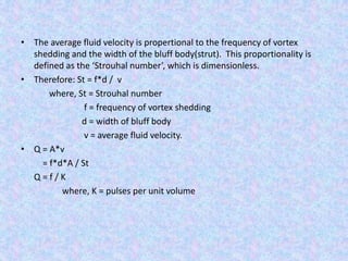
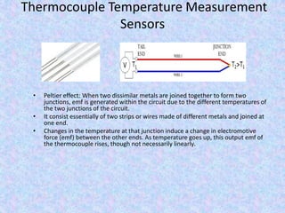
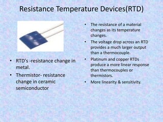
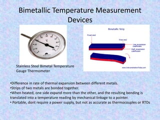
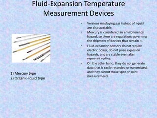
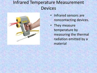
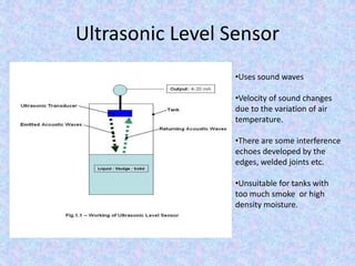
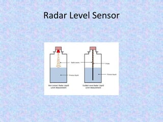
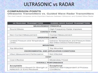
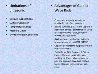
``
INSTRUMENTATION IN OIL REFINERY
PARAMETERS MEASURED IN OIL
REFINERY
1)Pressure
2)Temperature
3)Flow Rate
4)Level & many more.
FLOW RATE MEASUREMENT
FLOW MEASURING DEVICES
• Venturimeter
• Orifice Plate
• Flow Nozzels
• Pitot Tubes
• Rotameter
• Electromagnetic Flow Meter
• Turbine Meter
• Ultrasonic Flow Meter
• Vortex flow meter
Principles of Fluid Flow in Pipes
• Continuity equation:
• Bernoulli equation:
• Flow rate:
Q=
𝑉𝑜𝑙𝑢𝑚𝑒(𝑉)
𝑇𝑖𝑚𝑒(𝑡)
= Velocity(v) × Cross Section Area of pipe(A)
VENTURIMETER
• A Venturimeter is an instrument used to measure the rate of
discharge in a pipe line and is often fixed permanently at
different sections of the pipe line to know discharge there.
• It is the application of Bernoulli’s theorem.
• It may be used in any position, horizontal, vertical and
inclined.
• It consist of three parts
1. A short converging part
2. Throat
3. Long Diverging part
VENTURIMETER
𝑉2 𝑉1 < 𝑉2
𝑃1 > 𝑃2
𝐴1 > 𝐴2
𝐴1
𝐴2
𝑃1
𝑃2
Manometer
Pipe
Throat
Using Bernoulli’s equation and Continuity equation we can find discharge in the pipe.
Theoretically given by;
• Practically discharge value is given by below equation
• Where 𝑐 𝑑 is Co-efficient of discharge
• 𝑐 𝑑=
𝑄 𝑎𝑐𝑡𝑢𝑎𝑙
𝑄 𝑡ℎ𝑒𝑜𝑟𝑖𝑡𝑖𝑐𝑎𝑙
• Value of 𝑐 𝑑is between 0.96 to 0.98
• Low head loss (About 10% differential pressure head)
Orifice Meter
𝑉1 < 𝑉0
𝑃1 > 𝑃0
𝐴1 > 𝐴0
Orifice Plate
• In orifice meter cross section decrease suddenly so
there are in some part turbulent flow therefor some
energy loss in that portion.
Orifice Plate Meter
• Where K is called ‘orifice flow constant’,
• And E is thermal expansion correction factor.
• Value of 𝑐 𝑑 is around 0.6, Susceptible to inaccuracies resulting from erosion,
corrosion, and sealing.
𝑸 𝒂𝒄𝒕
• Flow rate is given by
Flow Nozzles
𝑉1 < 𝑉2
𝑃1 > 𝑃2
𝐴1 > 𝐴2
• The nozzle combines some of the best features of the orifice plate and Venturi tube.
• It is compact and yet, because of its curved inlet, has a discharge coefficient close to
unity.
• They have higher coefficient of discharge than that of orifice meter.
• Being more rugged and more resistant to erosion than sharp edge orifice, they can be
used for flow measurement at high velocities.
Pitot Tube
TP= Total Pressure
SP= Static Pressure
VP= Velocity Pressure
∆H
SP + VP = TP
𝑃0
ρ𝑔
+
𝑉2
2𝑔
=
𝑃𝑠
ρ𝑔
𝑉2
2𝑔
= ∆H
V= 2𝑔∆H
• Flow rate (Q) = A* 2𝑔∆H
• Cannot be used for industrial application which requires
an instant readout.
• Requires high flow velocity of about 15 m/s to produce
measurable head.
Rotameter
• In equilibrium Gravity force = force due to flow in upward direction
• The flow rate is proportional to the height of the bob.
• Less accurate, compared to venturimeter and orifice meter.
Ultrasonic Flow Meter
• A pair of transducers are installed on the outer surface of the pipe as shown in the
diagram. Each transducer works alternatively as both transmitter and receiver of
ultrasonic signals.
• Signal transmitted against the flow ,time required to receive it 𝑇1 = 𝑇𝑢𝑝
• Signal transmitted towards the flow ,time 𝑇2 = 𝑇𝑑𝑜𝑤𝑛 (𝑇1 > 𝑇2)
Ɵ
• Velocity of fluid is given by
• Where, Ɵ is angle b/w sound path and flow direction
D is the diameter of the pipe
M is the number of times the sound traverses the flow
ΔT = 𝑇𝑢𝑝 − 𝑇𝑑𝑜𝑤𝑛
• Flow rate Q = (velocity )(Cross section area)
• High accuracy.
• Excellent dynamic response
• Output is insensitive to variations in viscosity, density and temperature.
Turbine meter
• Turbine flow meter is an accurate and reliable flow meter.
• It consist of multi- bladed rotor mounted at right angles to the flow and
suspended in the fluid on a free running bearing.
• The rotor speed of rotation is proportional to the volumetric flow rate.
Turbine rotation can be detected by slid state devices(inductance,
capacitive, reluctance, hall effect pick up) or by mechanical sensor (gear or
magnetic drives).
• Flow rate is given by below equation
• Where, f = pulse frequency
𝐾𝑓𝑙𝑜𝑤 = Flow coefficient, its depends on flow rate and the
viscosity.
Electromagnetic Flow Meter
• Faraday’s low states that, whenever a conductor of length ‘l’ move with
velocity ‘v’ perpendicular to magnetic field ‘B’ , an emf ‘e’ induced in
mutually perpendicular direction which is given by
e= Blv where, B= Magnetic flux density(Wb / 𝑚2)
l = length of conductor(m)
v = velocity of conductor
• The volumetric flow rate Q is given by
Q = A(v)
= A(
𝑒
𝐵𝑙
)
=
𝜋𝐷2 𝑒
4𝐵𝑙
Q = Ke where, K = meter constant
Vortex Flow Meter
• The average fluid velocity is propertional to the frequency of vortex
shedding and the width of the bluff body(strut). This proportionality is
defined as the ‘Strouhal number’, which is dimensionless.
• Therefore: St = f*d / v
where, St = Strouhal number
f = frequency of vortex shedding
d = width of bluff body
v = average fluid velocity.
• Q = A*v
= f*d*A / St
Q = f / K
where, K = pulses per unit volume
TEMPERATURE
MEASUREMENT
INTRODUCTION
• Temperature can be measured via a diverse array of
sensors. All of them infer temperature by sensing
some change in a physical characteristic.
• Temperature is one of the most measured
parameters within industry and science. A correct
measurement is of great importance to the quality of
the product, as well as to security and to energy
consumption. Therefore, it is very important to
choose the right sensor for the actual application.
Thermocouple Temperature Measurement
Sensors
• Peltier effect: When two dissimilar metals are joined together to form two
junctions, emf is generated within the circuit due to the different temperatures of
the two junctions of the circuit.
• It consist essentially of two strips or wires made of different metals and joined at
one end.
• Changes in the temperature at that junction induce a change in electromotive
force (emf) between the other ends. As temperature goes up, this output emf of
the thermocouple rises, though not necessarily linearly.
Resistance Temperature Devices(RTD)
• RTD's -resistance change in
metal.
• Thermistor- resistance
change in ceramic
semiconductor
• The resistance of a material
changes as its temperature
changes.
• The voltage drop across an RTD
provides a much larger output
than a thermocouple.
• Platinum and copper RTDs
produce a more linear response
than thermocouples or
thermistors.
• More linearity & sensitivity.
Bimetallic Temperature Measurement
Devices
Stainless Steel Bimetal Temperature
Gauge Thermometer
•Difference in rate of thermal expansion between different metals.
•Strips of two metals are bonded together.
•When heated, one side expand more than the other, and the resulting bending is
translated into a temperature reading by mechanical linkage to a pointer.
• Portable, dont require a power supply, but not as accurate as thermocouples or RTDs
Fluid-Expansion Temperature
Measurement Devices
• Versions employing gas instead of liquid
are also available.
• Mercury is considered an environmental
hazard, so there are regulations governing
the shipment of devices that contain it.
• Fluid-expansion sensors do not require
electric power, do not pose explosion
hazards, and are stable even after
repeated cycling.
• On the other hand, they do not generate
data that is easily recorded or transmitted,
and they cannot make spot or point
measurements.
1) Mercury type
2) Organic-liquid type
Infrared Temperature Measurement
Devices
• Infrared sensors are
noncontacting devices.
• They measure
temperature by
measuring the thermal
radiation emitted by a
material
Infrared Temperature Measurement
Devices
Thermowell
•Thermowells are tubular fittings used to
protect temperature sensors installed in
industrial processes.
•It protects against corrosive process
media, as
•well as media contained under pressure
or flowing at a high velocity.
•they are used to provide an isolation
between a temperature sensor and the
environment, either liquid, gas or slurry.
•A thermowell allows the temperature
sensor to be removed and replaced
without compromising either the
ambient region or the process.
LEVEL MEASUREMENT
• Integral to process control in many industries
• Two main types:
1) Point level measurement
2) Continuous level measurement
Point level
measurment
• Functions as high alarm
-overfilling conditions
or as a marker for low
level conditions.
• More sophisticated
• Provide level
monitoring of entire
system.
• They measure fluid
level within a range,
rather than at a one
point, producing an
analog output that
directly correlates to
the level in the vessel.
Continuos level
measurement
Ultrasonic Level Sensor
•Uses sound waves
•Velocity of sound changes
due to the variation of air
temperature.
•There are some interference
echoes developed by the
edges, welded joints etc.
•Unsuitable for tanks with
too much smoke or high
density moisture.
Radar Level Sensor
ULTRASONIC vs RADAR
• Limitations of
ultrasonic
• Vacuum Applications
• Surface Condition
• Temperature Limits
• Pressure Limits
• Environmental Conditions
• Advantages of Guided
Wave Radar
• Changes in viscosity, density, or
acidity do not effect accuracy
• Boiling surfaces, dust, foam, vapor do
not effect device performance. Used
for Recirculating fluids, propeller
mixers, aeration tanks
• GWR performs well under extreme
temperatures up to 600ºF (315ºC)
• Capable of withstanding pressures up
to 580 PSI(40 Bar)
• Suitable for Fine Powders & Sticky
Fluids,- Vacuum tanks with used
cooking oil ,Paint, latex, animal fat
and soy bean oil ,Saw dust, carbon
black, titanium tetrachloride, salt,
grain
Instrumentation in oil refinery

Instrumentation in oil refinery

  • 1.
  • 2.
    PARAMETERS MEASURED INOIL REFINERY 1)Pressure 2)Temperature 3)Flow Rate 4)Level & many more.
  • 3.
  • 4.
    FLOW MEASURING DEVICES •Venturimeter • Orifice Plate • Flow Nozzels • Pitot Tubes • Rotameter • Electromagnetic Flow Meter • Turbine Meter • Ultrasonic Flow Meter • Vortex flow meter
  • 5.
    Principles of FluidFlow in Pipes • Continuity equation: • Bernoulli equation: • Flow rate: Q= 𝑉𝑜𝑙𝑢𝑚𝑒(𝑉) 𝑇𝑖𝑚𝑒(𝑡) = Velocity(v) × Cross Section Area of pipe(A)
  • 6.
    VENTURIMETER • A Venturimeteris an instrument used to measure the rate of discharge in a pipe line and is often fixed permanently at different sections of the pipe line to know discharge there. • It is the application of Bernoulli’s theorem. • It may be used in any position, horizontal, vertical and inclined. • It consist of three parts 1. A short converging part 2. Throat 3. Long Diverging part
  • 7.
    VENTURIMETER 𝑉2 𝑉1 <𝑉2 𝑃1 > 𝑃2 𝐴1 > 𝐴2 𝐴1 𝐴2 𝑃1 𝑃2 Manometer Pipe Throat Using Bernoulli’s equation and Continuity equation we can find discharge in the pipe. Theoretically given by;
  • 8.
    • Practically dischargevalue is given by below equation • Where 𝑐 𝑑 is Co-efficient of discharge • 𝑐 𝑑= 𝑄 𝑎𝑐𝑡𝑢𝑎𝑙 𝑄 𝑡ℎ𝑒𝑜𝑟𝑖𝑡𝑖𝑐𝑎𝑙 • Value of 𝑐 𝑑is between 0.96 to 0.98 • Low head loss (About 10% differential pressure head)
  • 9.
    Orifice Meter 𝑉1 <𝑉0 𝑃1 > 𝑃0 𝐴1 > 𝐴0 Orifice Plate • In orifice meter cross section decrease suddenly so there are in some part turbulent flow therefor some energy loss in that portion.
  • 10.
    Orifice Plate Meter •Where K is called ‘orifice flow constant’, • And E is thermal expansion correction factor. • Value of 𝑐 𝑑 is around 0.6, Susceptible to inaccuracies resulting from erosion, corrosion, and sealing. 𝑸 𝒂𝒄𝒕 • Flow rate is given by
  • 11.
    Flow Nozzles 𝑉1 <𝑉2 𝑃1 > 𝑃2 𝐴1 > 𝐴2 • The nozzle combines some of the best features of the orifice plate and Venturi tube. • It is compact and yet, because of its curved inlet, has a discharge coefficient close to unity.
  • 12.
    • They havehigher coefficient of discharge than that of orifice meter. • Being more rugged and more resistant to erosion than sharp edge orifice, they can be used for flow measurement at high velocities.
  • 13.
    Pitot Tube TP= TotalPressure SP= Static Pressure VP= Velocity Pressure ∆H
  • 14.
    SP + VP= TP 𝑃0 ρ𝑔 + 𝑉2 2𝑔 = 𝑃𝑠 ρ𝑔 𝑉2 2𝑔 = ∆H V= 2𝑔∆H • Flow rate (Q) = A* 2𝑔∆H • Cannot be used for industrial application which requires an instant readout. • Requires high flow velocity of about 15 m/s to produce measurable head.
  • 15.
    Rotameter • In equilibriumGravity force = force due to flow in upward direction • The flow rate is proportional to the height of the bob. • Less accurate, compared to venturimeter and orifice meter.
  • 16.
    Ultrasonic Flow Meter •A pair of transducers are installed on the outer surface of the pipe as shown in the diagram. Each transducer works alternatively as both transmitter and receiver of ultrasonic signals. • Signal transmitted against the flow ,time required to receive it 𝑇1 = 𝑇𝑢𝑝 • Signal transmitted towards the flow ,time 𝑇2 = 𝑇𝑑𝑜𝑤𝑛 (𝑇1 > 𝑇2) Ɵ
  • 17.
    • Velocity offluid is given by • Where, Ɵ is angle b/w sound path and flow direction D is the diameter of the pipe M is the number of times the sound traverses the flow ΔT = 𝑇𝑢𝑝 − 𝑇𝑑𝑜𝑤𝑛 • Flow rate Q = (velocity )(Cross section area) • High accuracy. • Excellent dynamic response • Output is insensitive to variations in viscosity, density and temperature.
  • 18.
  • 19.
    • Turbine flowmeter is an accurate and reliable flow meter. • It consist of multi- bladed rotor mounted at right angles to the flow and suspended in the fluid on a free running bearing. • The rotor speed of rotation is proportional to the volumetric flow rate. Turbine rotation can be detected by slid state devices(inductance, capacitive, reluctance, hall effect pick up) or by mechanical sensor (gear or magnetic drives). • Flow rate is given by below equation • Where, f = pulse frequency 𝐾𝑓𝑙𝑜𝑤 = Flow coefficient, its depends on flow rate and the viscosity.
  • 20.
  • 21.
    • Faraday’s lowstates that, whenever a conductor of length ‘l’ move with velocity ‘v’ perpendicular to magnetic field ‘B’ , an emf ‘e’ induced in mutually perpendicular direction which is given by e= Blv where, B= Magnetic flux density(Wb / 𝑚2) l = length of conductor(m) v = velocity of conductor • The volumetric flow rate Q is given by Q = A(v) = A( 𝑒 𝐵𝑙 ) = 𝜋𝐷2 𝑒 4𝐵𝑙 Q = Ke where, K = meter constant
  • 22.
  • 23.
    • The averagefluid velocity is propertional to the frequency of vortex shedding and the width of the bluff body(strut). This proportionality is defined as the ‘Strouhal number’, which is dimensionless. • Therefore: St = f*d / v where, St = Strouhal number f = frequency of vortex shedding d = width of bluff body v = average fluid velocity. • Q = A*v = f*d*A / St Q = f / K where, K = pulses per unit volume
  • 24.
  • 25.
    INTRODUCTION • Temperature canbe measured via a diverse array of sensors. All of them infer temperature by sensing some change in a physical characteristic. • Temperature is one of the most measured parameters within industry and science. A correct measurement is of great importance to the quality of the product, as well as to security and to energy consumption. Therefore, it is very important to choose the right sensor for the actual application.
  • 26.
    Thermocouple Temperature Measurement Sensors •Peltier effect: When two dissimilar metals are joined together to form two junctions, emf is generated within the circuit due to the different temperatures of the two junctions of the circuit. • It consist essentially of two strips or wires made of different metals and joined at one end. • Changes in the temperature at that junction induce a change in electromotive force (emf) between the other ends. As temperature goes up, this output emf of the thermocouple rises, though not necessarily linearly.
  • 27.
    Resistance Temperature Devices(RTD) •RTD's -resistance change in metal. • Thermistor- resistance change in ceramic semiconductor • The resistance of a material changes as its temperature changes. • The voltage drop across an RTD provides a much larger output than a thermocouple. • Platinum and copper RTDs produce a more linear response than thermocouples or thermistors. • More linearity & sensitivity.
  • 28.
    Bimetallic Temperature Measurement Devices StainlessSteel Bimetal Temperature Gauge Thermometer •Difference in rate of thermal expansion between different metals. •Strips of two metals are bonded together. •When heated, one side expand more than the other, and the resulting bending is translated into a temperature reading by mechanical linkage to a pointer. • Portable, dont require a power supply, but not as accurate as thermocouples or RTDs
  • 29.
    Fluid-Expansion Temperature Measurement Devices •Versions employing gas instead of liquid are also available. • Mercury is considered an environmental hazard, so there are regulations governing the shipment of devices that contain it. • Fluid-expansion sensors do not require electric power, do not pose explosion hazards, and are stable even after repeated cycling. • On the other hand, they do not generate data that is easily recorded or transmitted, and they cannot make spot or point measurements. 1) Mercury type 2) Organic-liquid type
  • 30.
    Infrared Temperature Measurement Devices •Infrared sensors are noncontacting devices. • They measure temperature by measuring the thermal radiation emitted by a material
  • 31.
  • 32.
    Thermowell •Thermowells are tubularfittings used to protect temperature sensors installed in industrial processes. •It protects against corrosive process media, as •well as media contained under pressure or flowing at a high velocity. •they are used to provide an isolation between a temperature sensor and the environment, either liquid, gas or slurry. •A thermowell allows the temperature sensor to be removed and replaced without compromising either the ambient region or the process.
  • 33.
    LEVEL MEASUREMENT • Integralto process control in many industries • Two main types: 1) Point level measurement 2) Continuous level measurement
  • 34.
    Point level measurment • Functionsas high alarm -overfilling conditions or as a marker for low level conditions. • More sophisticated • Provide level monitoring of entire system. • They measure fluid level within a range, rather than at a one point, producing an analog output that directly correlates to the level in the vessel. Continuos level measurement
  • 35.
    Ultrasonic Level Sensor •Usessound waves •Velocity of sound changes due to the variation of air temperature. •There are some interference echoes developed by the edges, welded joints etc. •Unsuitable for tanks with too much smoke or high density moisture.
  • 36.
  • 37.
  • 38.
    • Limitations of ultrasonic •Vacuum Applications • Surface Condition • Temperature Limits • Pressure Limits • Environmental Conditions • Advantages of Guided Wave Radar • Changes in viscosity, density, or acidity do not effect accuracy • Boiling surfaces, dust, foam, vapor do not effect device performance. Used for Recirculating fluids, propeller mixers, aeration tanks • GWR performs well under extreme temperatures up to 600ºF (315ºC) • Capable of withstanding pressures up to 580 PSI(40 Bar) • Suitable for Fine Powders & Sticky Fluids,- Vacuum tanks with used cooking oil ,Paint, latex, animal fat and soy bean oil ,Saw dust, carbon black, titanium tetrachloride, salt, grain