Download to read offline

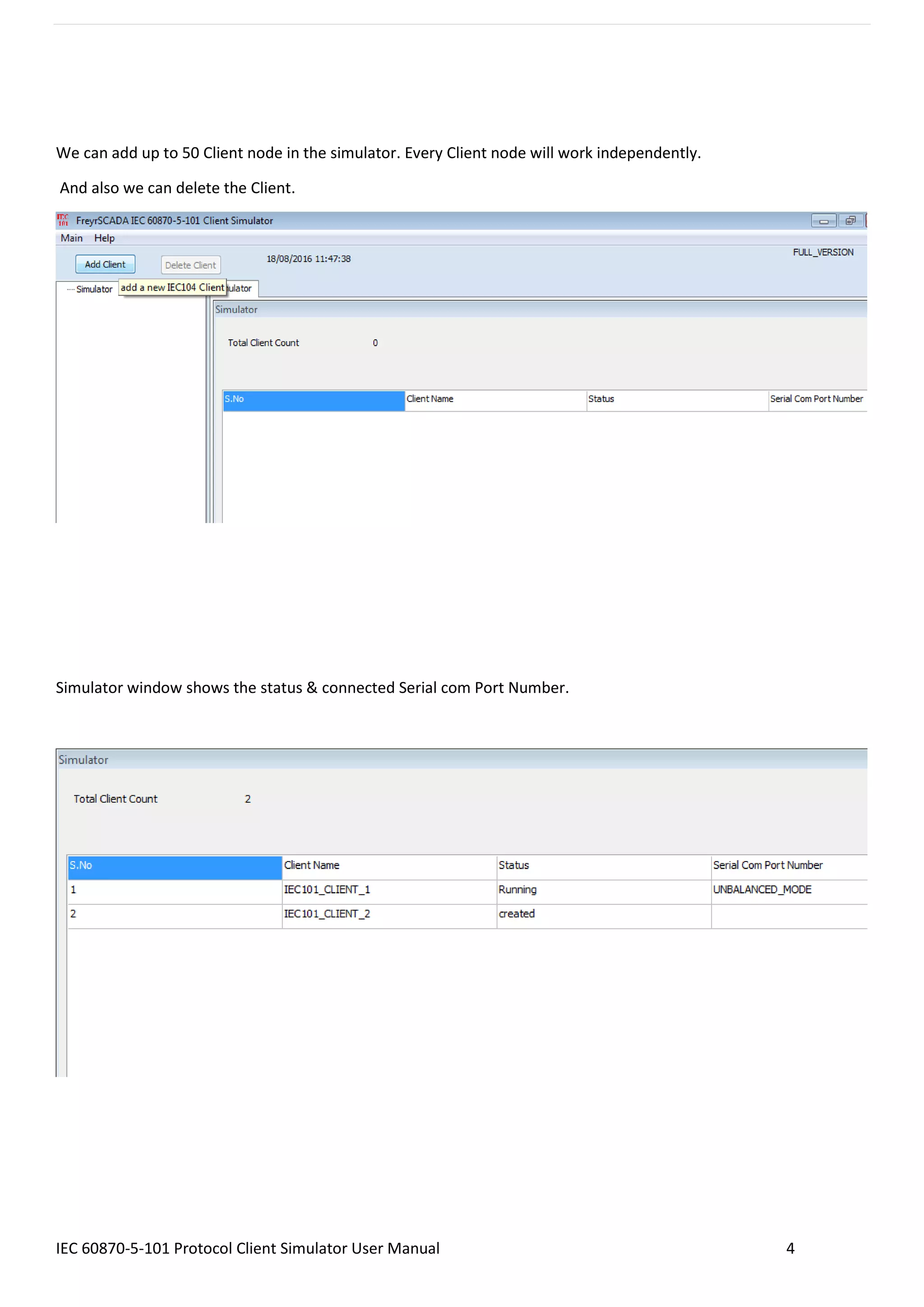
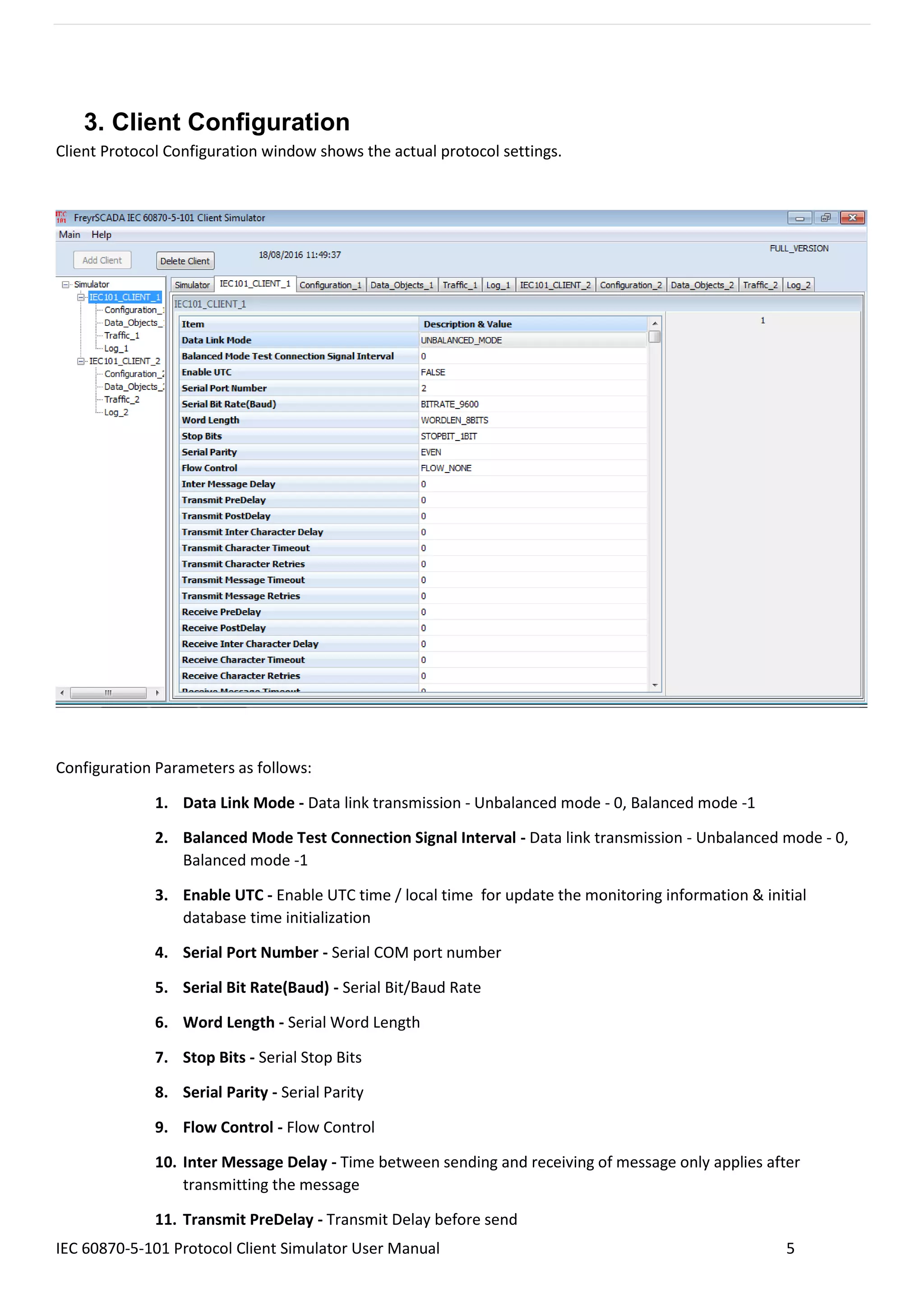

The IEC 60870-5-101 Protocol Client Master Simulator User Manual provides detailed instructions on configuring and using the client simulator, which is designed for power system monitoring and control in compliance with the IEC standards. Features include the ability to add up to 50 independent client nodes, support for different data transfer modes, and various configuration parameters for data transmission and station commands. The manual also outlines tools for monitoring communication traffic and logging command exchanges between the master and server.


