This document summarizes a master's thesis presentation on reliability analysis of wireless automotive applications with transceiver redundancy. The presentation covers:
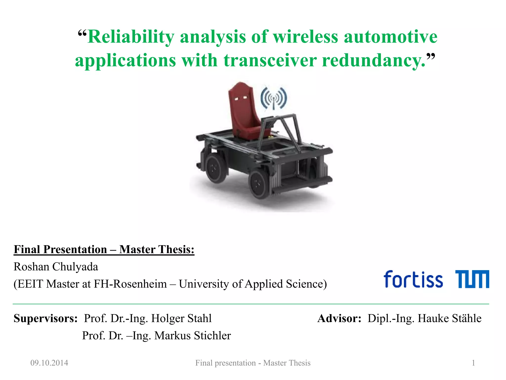
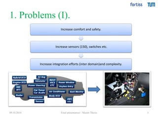
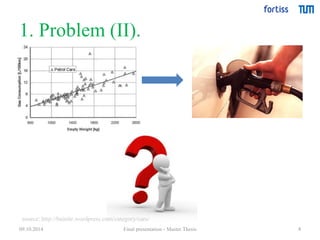
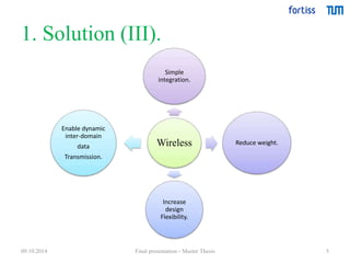
1) Problems with increasing sensors/integration in cars and the solution of using wireless transmission
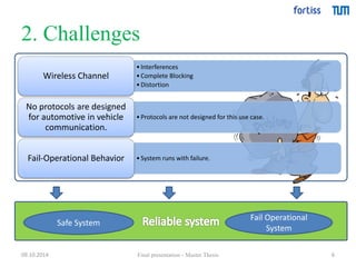
2) Challenges of wireless communication in vehicles, including interferences and lack of dedicated protocols
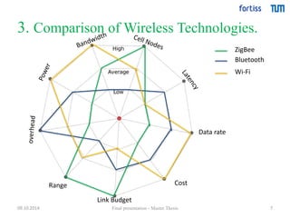
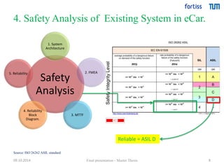
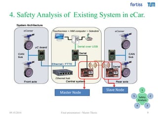
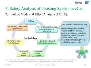
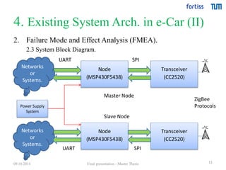
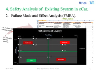
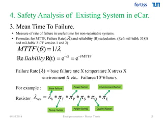
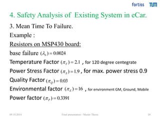
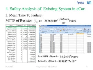
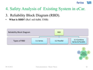
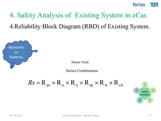
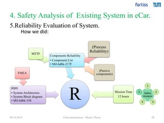
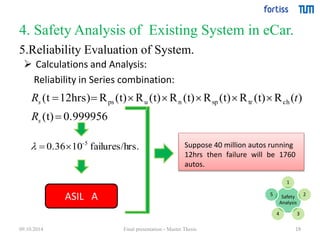
3) A safety analysis of an existing wireless system in an electric car, including FMEA, MTTF calculation, and reliability block diagram
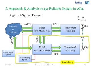
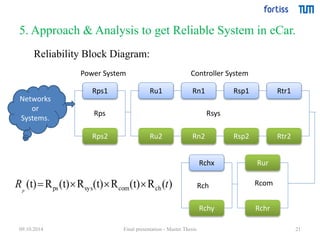
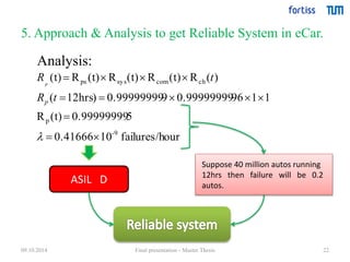
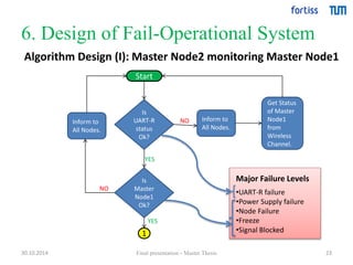
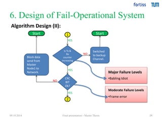
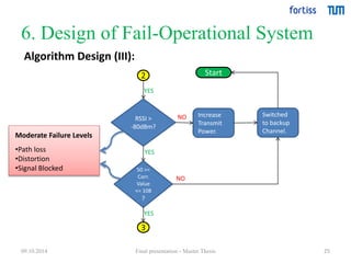
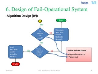
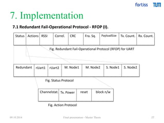
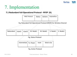
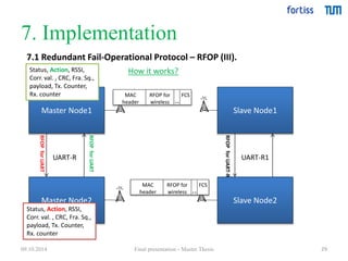
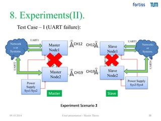
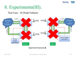
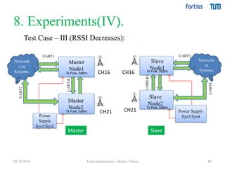
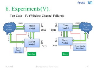
4) An approach and analysis to design a reliable redundant system in a car using parallel transceivers and channels analyzed through reliability block diagram and calculations.