This document provides a reference manual for troubleshooting network connectivity issues in Lab 1. It contains contents and explanations for various troubleshooting commands and approaches, including extended traceroute, the terminal monitor command, basic troubleshooting methodology, resolving or escalating issues, verification tools like ping and traceroute, duplex operation and mismatch troubleshooting, and addressing issues on IOS devices. The manual is intended solely for use in DCN330.
![Extended traceroute
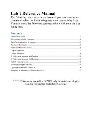
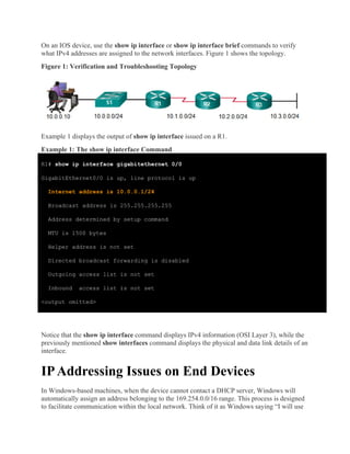
Designed as a variation of the traceroute command, the extended traceroute command allows the
administrator to adjust parameters related to the command operation. This is helpful when
troubleshooting routing loops, determining the exact next-hop router, or to help determine where
packets are getting dropped by a router or denied by a firewall. While the extended ping command
can be used to determine the type of connectivity problem, the extended traceroute command is
useful in locating the problem.
An ICMP "time exceeded" error message indicates that a router in the path has seen and discarded
the packet. An ICMP "destination unreachable" error message indicates that a router has received
the packet, but discarded it because it could not be delivered. Like ping, traceroute uses ICMP echo
requests and echo replies. If the ICMP timer expires before an ICMP echo reply is
received, traceroute command output displays an asterisk (*).
In IOS, the extended traceroute command terminates when any of the following occur:
• The destination responds with an ICMP echo reply
• The user interrupts the trace with the escape sequence
Note: In IOS, you can invoke this escape sequence by pressing Ctrl+Shift+6. In Windows, the
escape sequence is invoked by pressing Ctrl+C.
To use extended traceroute, simply type traceroute, without providing any parameters, and
press ENTER. IOS will guide you through the command options by presenting a number of prompts
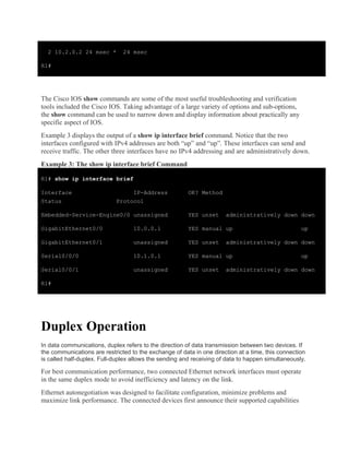
related to the setting of all the different parameters. Table 1 shows the IOS
extended traceroute options and their respective descriptions.
Table 1: IOS Extended traceroute Options
Option Description
Protocol [ip]: Prompts for a supported protocol. The default is IPv4.
Target IP
address:
You must enter a host name or an IPv4 address. There is no
default.
Source address: The interface or IPv4 address of the router to use as a source
address for the probes. The router normally picks the IPv4
address of the outbound interface to use.
Numeric display
[n]:
The default is to have both a symbolic and numeric display;
however, you can suppress the symbolic display.
Timeout in
seconds [3]:
The number of seconds to wait for a response to a probe packet.
The default is 3 seconds.](https://image.slidesharecdn.com/lab1referencemanual-171218205649/85/Lab-1-reference-manual-2-320.jpg)
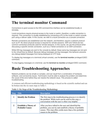
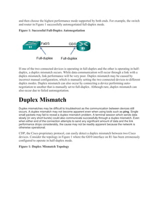
![Probe count
[3]:
The number of probes to be sent at each TTL level. The default
count is 3.
Minimum Time to
Live [1]:
The TTL value for the first probes. The default is 1, but it can be
set to a higher value to suppress the display of known hops.
Maximum Time to
Live [30]:
The largest TTL value that can be used. The default is 30.
The traceroutecommand terminates when the destination is
reached or when this value is reached.
Port Number
[33434]:
The destination port used by the UDP probe messages. The
default is 33434.
Loose, Strict,
Record,
Timestamp,
Verbose [none]:
IP header options. You can specify any combination.
The traceroutecommand issues prompts for the required fields.
Note that the traceroutecommand will place the requested
options in each probe; however, there is no guarantee that all
routers (or end nodes) will process the options.
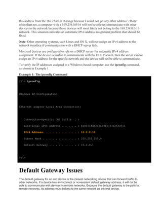
While the Windows tracert command allows the input of several parameters, it is not guided and
must be performed through options in the command line. Example 1 shows the available options
for tracert in Windows.
Example 1: Available options for tracert in Windows.
C:> tracert
Usage: tracert [-d] [-h maximum_hops] [-j host-list] [-w timeout]
[-R] [-S srcaddr] [-4] [-6] target_name
Options:
-d Do not resolve addresses to hostnames.
-h maximum_hops Maximum number of hops to search for target.
-j host-list Loose source route along host-list (IPv4-only).
-w timeout Wait timeout milliseconds for each reply.
-R Trace round-trip path (IPv6-only).
-S srcaddr Source address to use (IPv6-only).
-4 Force using IPv4.
-6 Force using IPv6.](https://image.slidesharecdn.com/lab1referencemanual-171218205649/85/Lab-1-reference-manual-3-320.jpg)
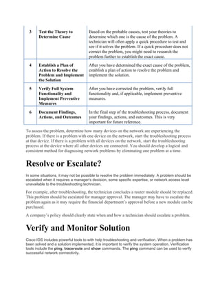
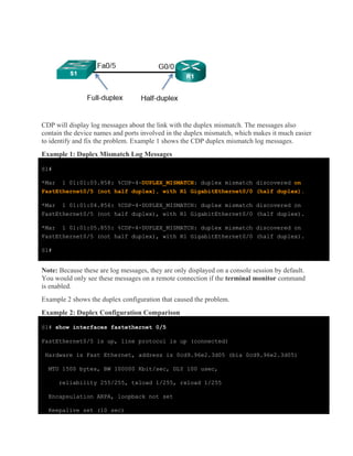
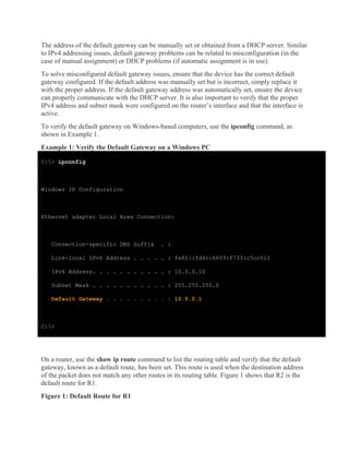
![Example 2 shows that the default gateway has been set with a default route of 10.1.0.2.
Example 2: Default gateway displayed in output of show ip route command
R1# show ip route
<output omitted>
Gateway of last resort is 10.1.0.2 to network 0.0.0.0
S* 0.0.0.0/0 [1/0] via 10.1.0.2
10.0.0.0/8 is variably subnetted, 4 subnets, 2 masks
C 10.0.0.0/24 is directly connected, GigabitEthernet0/0
L 10.0.0.1/32 is directly connected, GigabitEthernet0/0
C 10.1.0.0/24 is directly connected, Serial0/0/0
L 10.1.0.1/32 is directly connected, Serial0/0/0
R1#
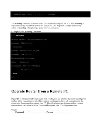
Troubleshooting DNS Issues
Domain Name Service (DNS) defines an automated service that matches names, such as
www.cisco.com, with the IP address. While DNS resolution is not crucial to device communication, it
is very important to the end user.
It is common for users to mistakenly relate the operation of an Internet link to the availability of
the DNS service. User complaints such as “the network is down” or “the Internet is down” are
often caused by an unreachable DNS server. While packet routing and all other network services
are still operational, DNS failures often lead the user to the wrong conclusion. If a user types in a
domain name such as www.cisco.com in a web browser and the DNS server is unreachable, the
name will not be translated into an IP address and the website will not display.](https://image.slidesharecdn.com/lab1referencemanual-171218205649/85/Lab-1-reference-manual-14-320.jpg)


![Internet Technology (Practical Questions Paper) [CBSGS - 75:25 Pattern] {2017...](https://cdn.slidesharecdn.com/ss_thumbnails/it-cbsgs-2017-manual-pq-190611111707-thumbnail.jpg?width=640&height=640&fit=bounds)


