Download to read offline

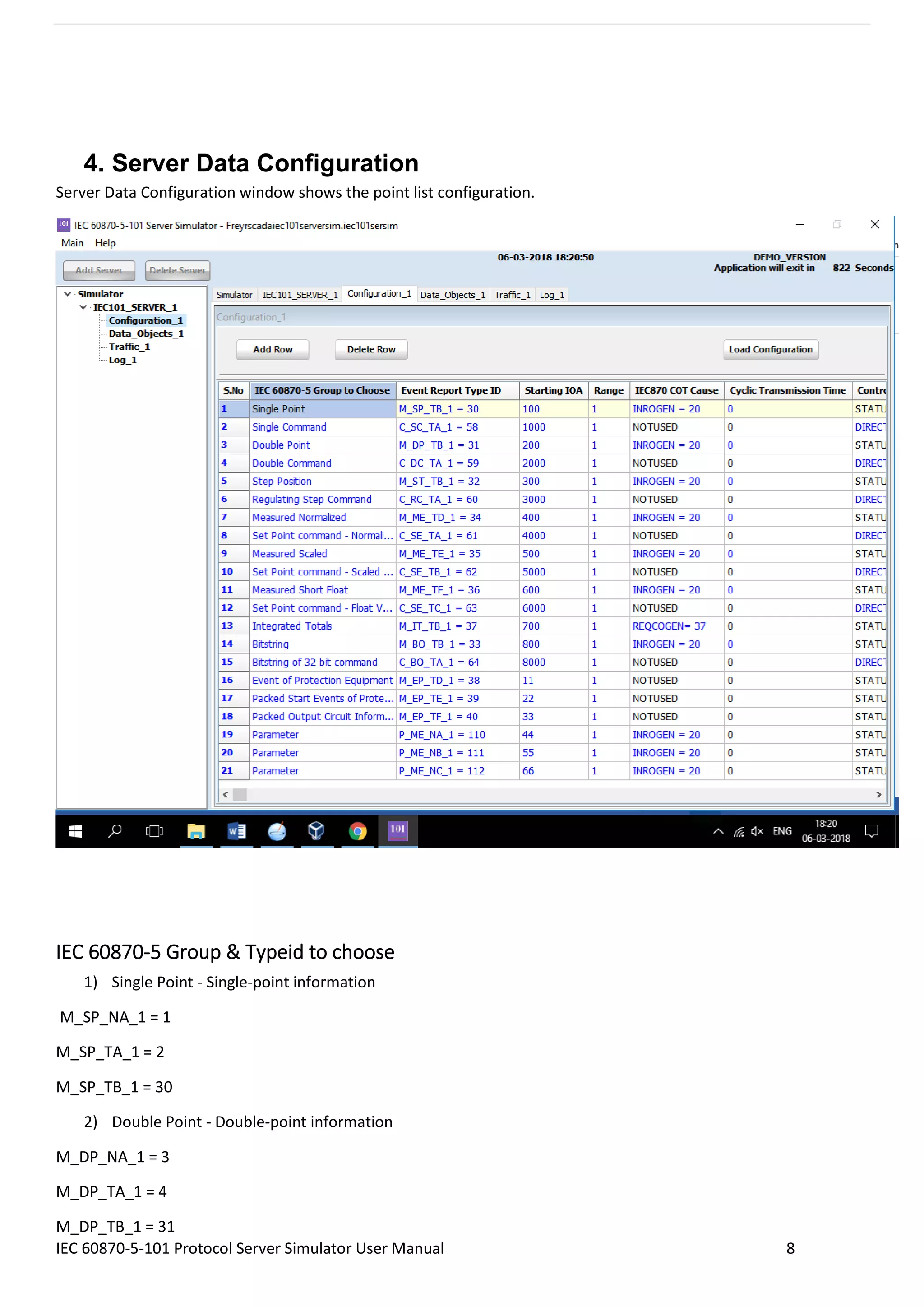
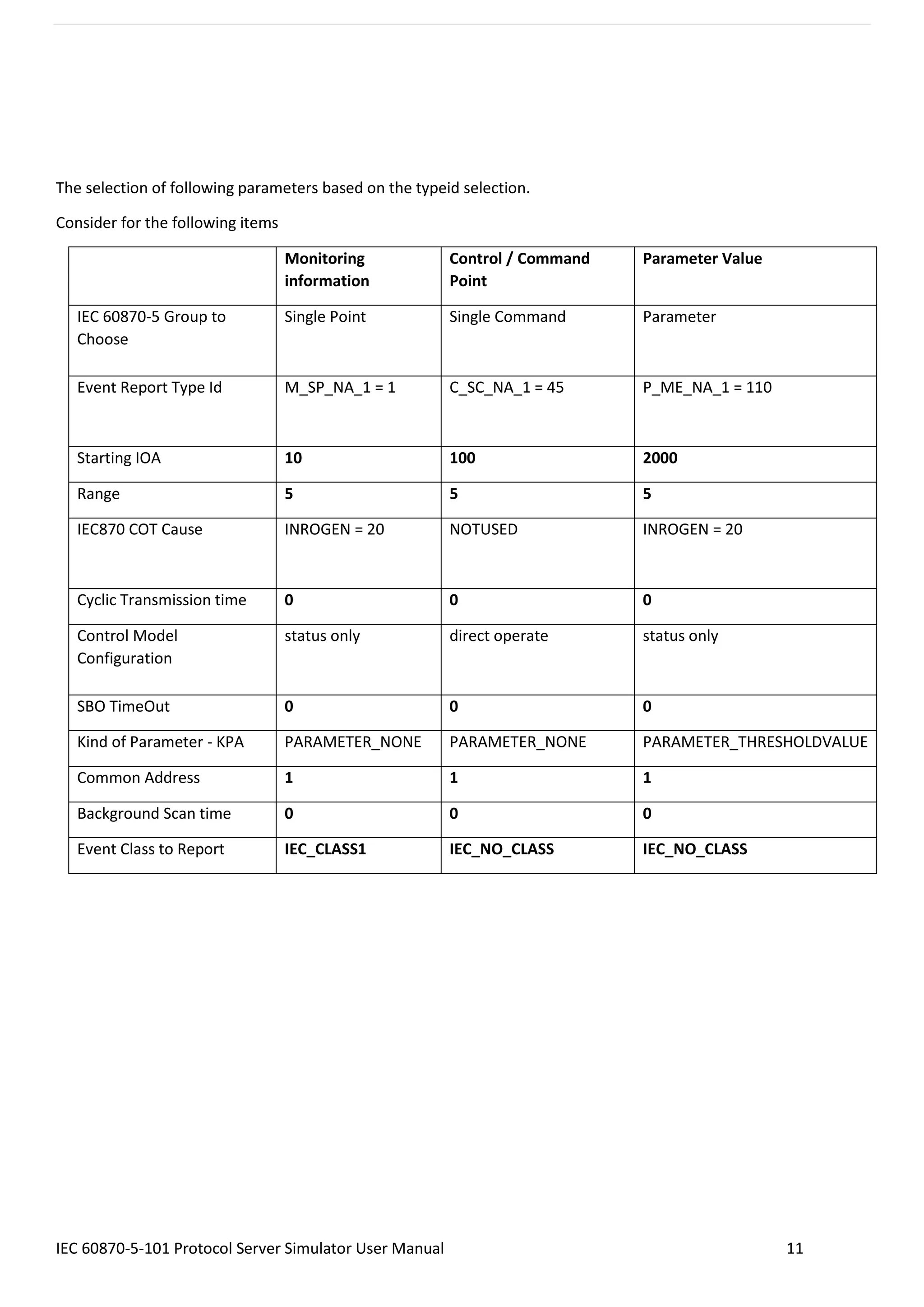
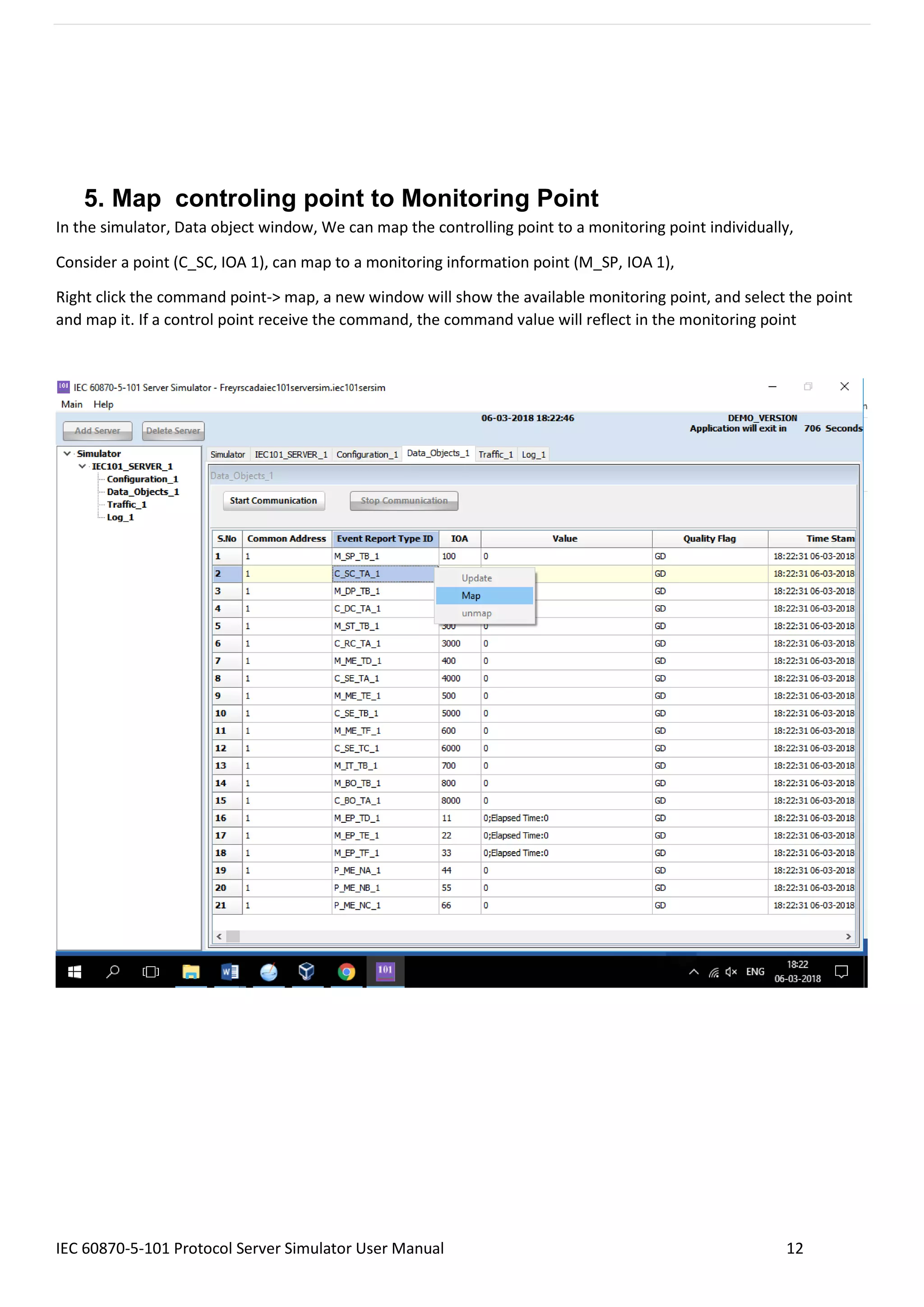
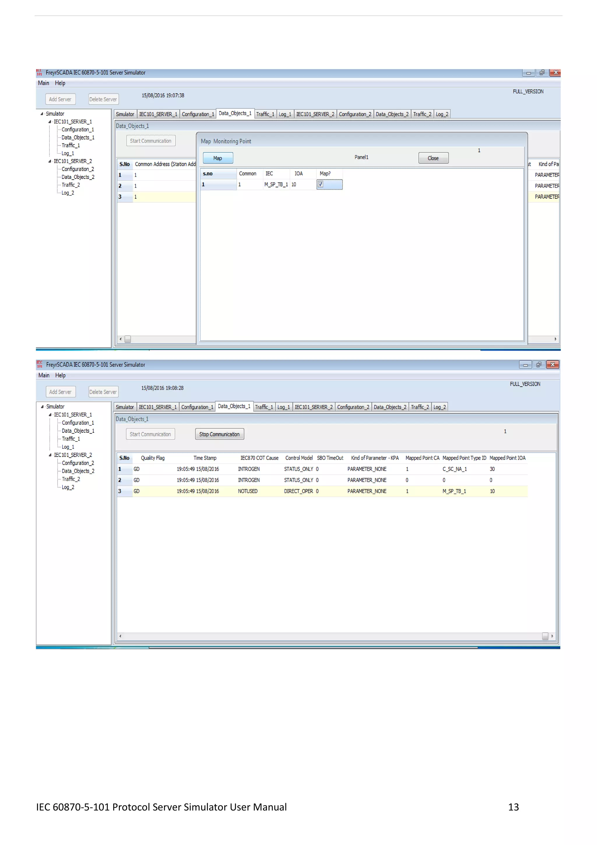
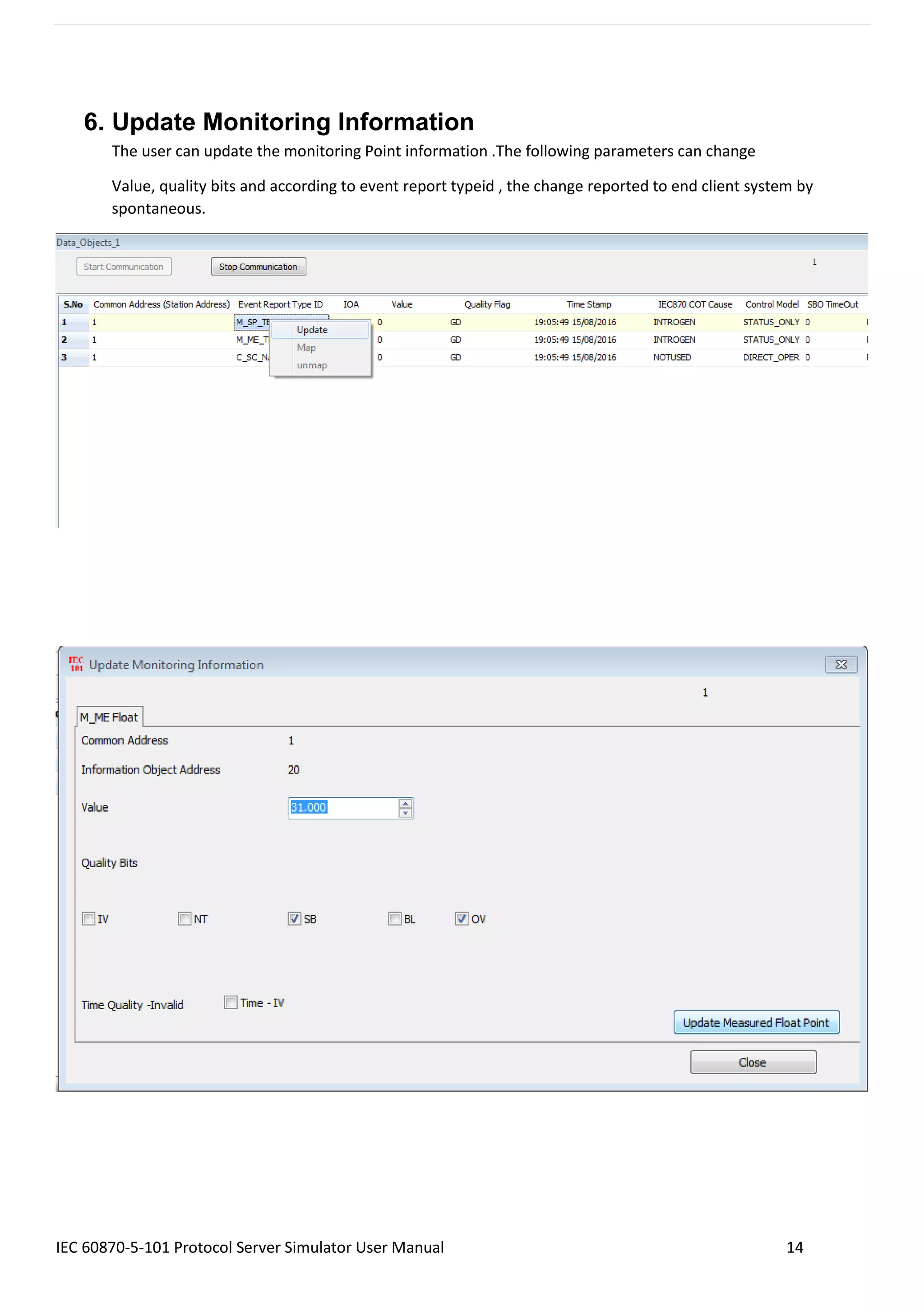

The IEC 60870-5-101 Protocol RTU IED Server Simulator User Manual provides comprehensive guidance on configuring and using the simulator for power system monitoring and control. It details server setup, data configuration, features of the protocol, and methods for mapping control points to monitoring points. Additionally, it contains instructions for managing server nodes and monitoring communication traffic.