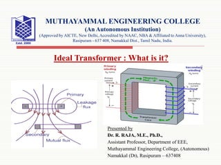
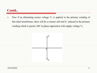
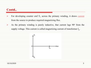
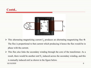
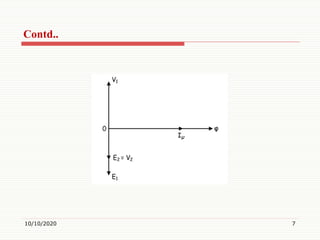
Presented by
Dr. R. RAJA, M.E., Ph.D.,
Assistant Professor, Department of EEE,
Muthayammal Engineering College, (Autonomous)
Namakkal (Dt), Rasipuram – 637408
MUTHAYAMMAL ENGINEERING COLLEGE
(An Autonomous Institution)
(Approved by AICTE, New Delhi, Accredited by NAAC, NBA & Affiliated to Anna University),
Rasipuram - 637 408, Namakkal Dist., Tamil Nadu, India.
Ideal Transformer : What is it?
Definition of Ideal Transformer
 An ideal transformer is an imaginary transformer which does not have any
loss in it, means no core losses, copper losses and any other losses in
transformer. Efficiency of this transformer is considered as 100%.
10/10/2020 2
Ideal Transformer Model
 The ideal transformer model is developed by considering the windings of the
transformer are purely inductive and the core of the transformer is loss free.
 Also there is zero leakage reactance of transformer (reactance is the opposition
to the flow of current from the circuit element due to its inductance and
capacitance).
 That means, 100% flux passes through the core and links with both the primary
and secondary windings of transformer.
 Although every winding must have some inharent resistance in it which causes
voltage drop and I2R loss in it.
 In such ideal transformer model, the windings are considered as ideal(fully
inductive), that means resistance of the winding is zero.
10/10/2020 3
 Now if an alternating source voltage V1 is applied in the primary winding of
that ideal transformer, there will be a counter self emf E1 induced in the primary
winding which is purely 180o in phase opposition with supply voltage V1.
10/10/2020 4
Contd..
 For developing counter emf E1 across the primary winding, it draws current
from the source to produce required magnetizing flux.
 As the primary winding is purely inductive, that current lags 90o from the
supply voltage. This current is called magnetizing current of transformer Iμ.
10/10/2020 5
Contd..
10/10/2020 6
 This alternating magnetizing current Iμ produces an alternating magnetizing flux Φ.
The flux is proportional to that current which producing it hence the flux would be in
phase with the current.
 This flux also links the secondary winding through the core of the transformer. As a
result, there would be another emf E2 induced across the secondary winding, and this
is mutually induced emf as shown in the figure below.
Contd..
10/10/2020 7
Contd..
Thank You
10/10/2020 8

Ideal Transformer

  • 1.
    Presented by Dr. R.RAJA, M.E., Ph.D., Assistant Professor, Department of EEE, Muthayammal Engineering College, (Autonomous) Namakkal (Dt), Rasipuram – 637408 MUTHAYAMMAL ENGINEERING COLLEGE (An Autonomous Institution) (Approved by AICTE, New Delhi, Accredited by NAAC, NBA & Affiliated to Anna University), Rasipuram - 637 408, Namakkal Dist., Tamil Nadu, India. Ideal Transformer : What is it?
  • 2.
    Definition of IdealTransformer  An ideal transformer is an imaginary transformer which does not have any loss in it, means no core losses, copper losses and any other losses in transformer. Efficiency of this transformer is considered as 100%. 10/10/2020 2
  • 3.
    Ideal Transformer Model The ideal transformer model is developed by considering the windings of the transformer are purely inductive and the core of the transformer is loss free.  Also there is zero leakage reactance of transformer (reactance is the opposition to the flow of current from the circuit element due to its inductance and capacitance).  That means, 100% flux passes through the core and links with both the primary and secondary windings of transformer.  Although every winding must have some inharent resistance in it which causes voltage drop and I2R loss in it.  In such ideal transformer model, the windings are considered as ideal(fully inductive), that means resistance of the winding is zero. 10/10/2020 3
  • 4.
     Now ifan alternating source voltage V1 is applied in the primary winding of that ideal transformer, there will be a counter self emf E1 induced in the primary winding which is purely 180o in phase opposition with supply voltage V1. 10/10/2020 4 Contd..
  • 5.
     For developingcounter emf E1 across the primary winding, it draws current from the source to produce required magnetizing flux.  As the primary winding is purely inductive, that current lags 90o from the supply voltage. This current is called magnetizing current of transformer Iμ. 10/10/2020 5 Contd..
  • 6.
    10/10/2020 6  Thisalternating magnetizing current Iμ produces an alternating magnetizing flux Φ. The flux is proportional to that current which producing it hence the flux would be in phase with the current.  This flux also links the secondary winding through the core of the transformer. As a result, there would be another emf E2 induced across the secondary winding, and this is mutually induced emf as shown in the figure below. Contd..
  • 7.
  • 8.