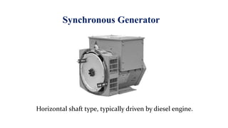
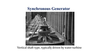
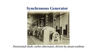
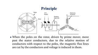
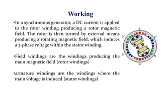
1) Synchronous generators have rotor windings that produce a rotating magnetic field and stator windings where 3-phase voltage is induced. They are driven by diesel engines, water turbines, or steam turbines.
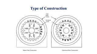
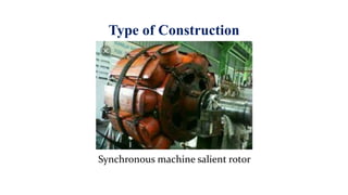
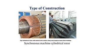
2) The rotor magnetic poles can be either salient (sticking out) or cylindrical construction and are made of laminated steel to reduce eddy currents. Stator windings are used because connections are easier than on the rotating rotor.
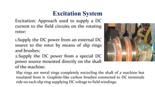
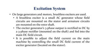
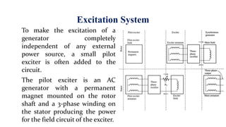
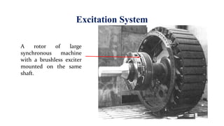
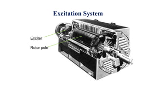
3) Excitation systems use slip rings and brushes or brushless exciters to supply DC current to the rotor windings. This produced the rotating magnetic field needed to induce voltage in the stator windings.