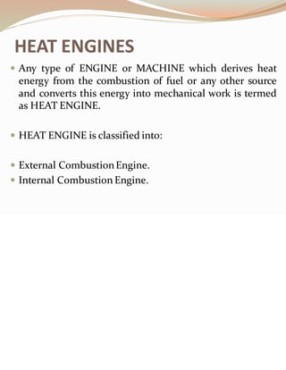
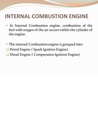
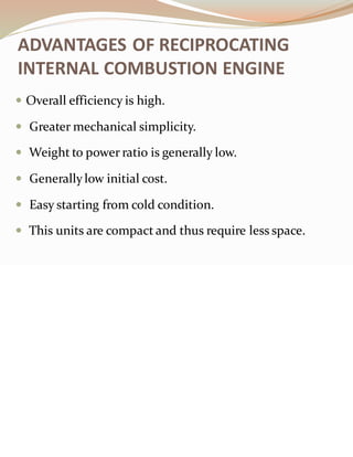
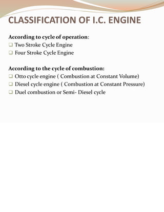
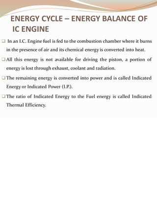
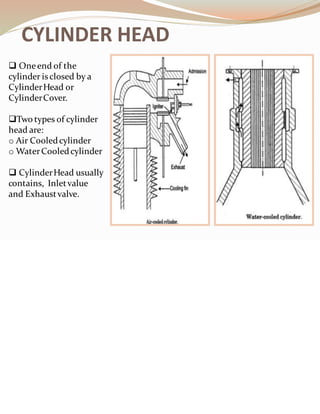
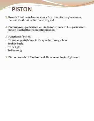
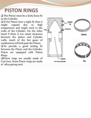
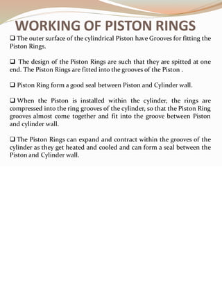
Extracted by:
DEBOLINA MUKHERJEE
From:
IC Engine by
R K RAJPUT
HEAT ENGINES
 Any type of ENGINE or MACHINE which derives heat
energy from the combustion of fuel or any other source
and converts this energy into mechanical work is termed
as HEAT ENGINE.
 HEAT ENGINE is classified into:
 External CombustionEngine.
 Internal Combustion Engine.
INTERNAL COMBUSTION ENGINE
 In Internal Combustion engine, combustion of the
fuel with oxygen of the air occurs within the cylinder of
the engine.
 The internal Combustionengine is grouped into:
❑ Petrol Engine ( Spark Ignition Engine)
❑ Diesel Engine ( Compression Ignition Engine)
ADVANTAGES OF RECIPROCATING
INTERNAL COMBUSTION ENGINE
 Overall efficiency is high.
 Greater mechanical simplicity.
 Weight to power ratio is generally low.
 Generallylow initial cost.
 Easy starting from cold condition.
 This units are compact and thus require less space.
CLASSIFICATION OF I.C. ENGINE
According to cycleof operation:
❑ Two Stroke Cycle Engine
❑ Four Stroke Cycle Engine
According to the cycle of combustion:
❑ Otto cycle engine ( Combustion at Constant Volume)
❑ Diesel cycle engine ( Combustion at Constant Pressure)
❑ Duel combustion or Semi- Diesel cycle
APPLICATION OF IC ENGINE
❑ Road Vehicles
❑ Aircraft
❑ Locomotives
❑ Construction in civil engineering equipments such as
bull-doser,scraper, power shovels, etc.
❑ Plumbing sets
❑ Cinemas
❑ Hospitals
❑ Several Industrial Applications
IC Engine can be generally used for :
ENERGY CYCLE – ENERGY BALANCE OF
IC ENGINE
❑ In an I.C. Engine fuel is fed to the combustion chamber where it burns
in the presence of air and its chemical energy is converted into heat.
❑All this energy is not available for driving the piston, a portion of
energy is lost through exhaust, coolant and radiation.
❑The remaining energy is converted into power and is called Indicated
Energy or Indicated Power (I.P.).
❑The ratio of Indicated Energy to the Fuel energy is called Indicated
Thermal Efficiency.
❑ The Energy available at the piston
passes through the connecting rod
to the crankshaft.
❑ In this transmission of energy or
power, there are losses due to
friction, pumping, etc.
❑ The sum of all those losses, termed
as power is known as frictional
power (F.P.)
❑ The remaining energy is the useful
mechanical energy known as shaft
energy or brake power (B.P.).
❑ The ratio of energy at the shaft to
fuel input energy is called Brake
Thermal Efficiency.
❑ The Ratio of Shaft energy to the
energy available at the piston is
known as Mechanical Efficiency.
ENERGY CYCLE – ENERGY BALANCE OF IC
ENGINE
WORKING OF IC ENGINE
❑ The cylinder which is closed at one end is
filledwith a mixture of fuel and air.
❑ As the crankshaft turns, it pushes the
connecting rod.
❑ The piston is forced up and compresses the
mixture in the topof the cylinder.
❑ The air fuel mixture is ignited and as it
burns it creates a gas pressure on the piston,
forcing it down the cylinder. The motion is
shown by arrow 1,
❑ The piston pushes on the rod which pushes
the crank.
❑ The Crank is given rotary or turning motion
as shown by the arrow.
PARTS OF IC ENGINE
❑ Cylinder
❑ Cylinder
Head
❑ Piston
❑ Piston Rings
❑ Gudgeon Pin
❑ Connecting
rod
❑ Crankshaft
❑ Crank
❑ Crank case
❑ Engine
bearing
❑ Flywheel
❑ Governor
❑ Valves and
valve
operating
mechanism
PARTS OF PETROL ENGINE
ONLY:
❑ SPARK PLUGS
❑ CARBURETOR
❑ FUEL PUMP
PARTS OF DIESEL ENGINE ONLY:
❑ FUEL PUMP
❑INJECTOR
CYLINDER
❑Cylinder contains gas under pressure and guides the Piston.
❑Cylinder is in direct contact with the product of combustion.
❑ The ideal type of Piston consists of plain cylindrical barrel in
which the Piston slides.
❑The upper end of the Cylinder is considered as Combustion or
clearance space in which the combustion of fuel takes place.
❑The Cylinder is made up of a hard grade Cast Iron and cast in
one piece.
CYLINDER HEAD
❑ Oneend of the
cylinder isclosed by a
CylinderHead or
CylinderCover.
❑Two types of cylinder
head are:
o Air Cooledcylinder
o WaterCooledcylinder
❑ CylinderHead usually
contains, Inletvalue
and Exhaustvalve.
PISTON
❑ Pistonis fittedto each cylinderas a face to receive gas pressure and
transmitthe thrust to the connecting rod.
❑ Pistonmoves up and down withinPistonCylinder. Thisup and down
motion is called the reciprocating motion.
❑ Functionsof Piston:
o To givean gas tightseal to thecylinderthrough bore.
o To slide freely.
o To be light.
o To be strong.
❑ Pistonaremade of Cast Iron and Aluminum alloyfor lightness.
PISTON RINGS
❑ The Piston must be a fairly loose fit
in the Cylinder.
❑ If the Piston have a tight fit then it
might expand due to high
temperature and might stick to the
walls of the Cylinder. On the other
hand if there is too much clearance
between the piston and Cylinder
walls, much of the hot gases of
combustion will leak past the Piston.
❑ To provide a good sealing fit
between the Piston and the Cylinder,
Piston are equipped with Piston
Rings.
❑Piston rings are usually made of
Cast Iron. Some Piston rings are made
of alloyspring steel.
WORKING OF PISTON RINGS
❑ The outer surface of the cylindrical Piston have Grooves for fitting the
Piston Rings.
❑ The design of the Piston Rings are such that they are spitted at one
end. The Piston Rings are fitted into the grooves of the Piston .
❑ Piston Ring form a good seal between Piston and Cylinder wall.
❑ When the Piston is installed within the cylinder, the rings are
compressed into the ring grooves of the cylinder, so that the Piston Ring
grooves almost come together and fit into the groove between Piston
and cylinder wall.
❑ The Piston Rings can expand and contract within the grooves of the
cylinder as they get heated and cooled and can form a seal between the
Piston and Cylinder wall.
WORKING OF PISTON RINGS
❑ The diagram shows how the Piston ring
works to hold the compression and
combustion pressure.
❑ The arrows shows the pressure above the
Piston and the Cylinder wall.
❑ The Piston rings ensure good seal
between the Piston and the Cylinder even at
high pressure.
CONNECTING ROD
❑ ConnectingRod connects the Pistontothe Crank.
❑Connecting Rod transmitsthe Pistonload to the
Crank causing the Crank to turn.
❑ The loweror “ big end” of the Connectingrod turns on
“ Crank Pin”.
❑The Pistonendof theconnecting rod is called “small
end” and the Crankend of the Connecting Rod is called
“big end”.
❑ Connecting Rod is made up of nickel, chromeand
chrome vanadium steel.
❑ Forsmall enginesthe materialsmay be aluminum.
CRANK
❑ The Piston moves up and down
withinthe enginecylinder.
❑ The reciprocating motion of the
Piston is converted to rotary motion
with the help of Crank and
ConnectingRod.
❑ This rotary motion is required to
make wheels turn.
CRANK SHAFT
❑ The Crankshaftis a shaft that is
connected to theConnecting Rod
throughthe Crank.
❑ As the Pistonmoves up and down,
the ConnectingRod connectedto it
also moves up and down and the
Crankconnected to the Connecting
Rod startsrotatingthuscausing the
Crankshaftto rotate. Thewheels
connected to theCrankshaftalso
rotatesas the Crankshaftrotates.
❑ Crank shaft is made of forged steel.
SPARK PLUG
❑ The Spark Plug is a device that produces
spark in the ignitionchamber for the
combustion of fuel.
❑ The Spark Plug consistsof a metal shell
having two electrodes which are insulatedfrom
each otherthroughan air gap.
❑The high ampcurrent supplied through the
supplyelectrode produce the necessary spark.
❑ Porcelain is used as the insulatingmaterial in
Spark Plug. Mica isalso used as the insulating
material in Spark Plug.
❑ Spark Plug must withstandpressure upto
55 bar.
❑ It must provide suitable insulation
between two electrodes toprevent short
circuiting.
❑ It must withstanda high temperature
upto 2000 ⁰ C and 2500 ⁰ C.
❑ It must possessa high temperature
resistanceso that the electrodedo not
become sufficientlyhot tocause the
preignitionof the charge / fuel withinthe
enginecylinder.
QUALITY REQUIRES IN SPARK PLUG
SIMPLE CARBURATOR
❑ The function of Carburetor is to atomizeand
meter the liquid fuel and mix it with the air as it
enters the induction systemof the engine,
maintaining underall conditions of operations the
correct fuel- air proportion.
❑ The diagram showsa Simple Carburetor .
❑ L = float chamber for the storage of fuel.
❑ F= filter.
❑ M= floatvalve
❑ N = Jet from which fuel is sprayed
❑ S = Inlet
❑ R = Throat / Venturi
❑ Q = Induction Manifold
❑ T = Throat Valve
SIMPLE CARBURATOR
❑ The diagram showsa Simple Carburetor.
❑ L is the float chamber for the storage of
fuel.
❑ The fuel supplied under gravity action or by
fuel pump enters the float chamber
through the filter F.
❑ The arrangement is such that when the oil
reaches a particular level, the float valve M
blocks the inlet passage and thus cuts off
the fuel oil supply.
❑ On the fall of oil level, the float descends
down consequently intake passage opens
and again the chamber is filled with oil.
❑ Then the float and the float valve
maintains a constant fuel oil level in the
float chamber.
❑ N is the jet from which the fuel is sprayed
into the air stream as it enters the
Carburetor at the inlet S and passes
through the throat / venturi R. The fuel
level is slightly below the outlet of the jet
when the carburetoris inoperative.
❑ As the Piston moves down through the
engine cylinder, vacuum is produced in the
engine cylinder as well as in the induction
manifold Q as a result of which air flows
through the Carburetor. The velocity of air
increases as it passes through the
construction at the venturi R and pressure
decreases due to the conversion of a
portion of pressure head into kinetic
energy.
❑ Due to decreased pressure at the venturi
and by virtue of differenceof pressure
( between the float chamber and venturi )
the jet sprays fuel oil into air stream.
❑ Since the jet has a very fine bore, the oil
flowing from the jet is in form of fine spray,
it vaporizesquicklyand mixes with air.
❑ The air-fuel mixture enters the engine
cylinder, its quantity being controlled by
varying the position of the Throttle valve T.
FLYWHEEL
❑ Flywheel is a Steel or Cast Iron disc that is
mountedon the Crankshaft.
❑ Flywheel is the componentof the IC
enginethat is mountedon the Crank Shaft.
❑ Flywheel helps in the following function:
o Startingtheengine.
o Overcomes thefluctuation of load.
o Makes theCrankshaft rotatesmore
uniform.
GOVERNOR
 Governor is a device that controls the output of a machine
or engine by regulating the Working fluid supplied i.e
controlling the supplyof fuel.
 Types of GOVERNOR:
❑ Centrifugal Governor
❑ Inertia Governor

Internal combustion engine 1

  • 1.
  • 2.
    HEAT ENGINES  Anytype of ENGINE or MACHINE which derives heat energy from the combustion of fuel or any other source and converts this energy into mechanical work is termed as HEAT ENGINE.  HEAT ENGINE is classified into:  External CombustionEngine.  Internal Combustion Engine.
  • 3.
    INTERNAL COMBUSTION ENGINE In Internal Combustion engine, combustion of the fuel with oxygen of the air occurs within the cylinder of the engine.  The internal Combustionengine is grouped into: ❑ Petrol Engine ( Spark Ignition Engine) ❑ Diesel Engine ( Compression Ignition Engine)
  • 4.
    ADVANTAGES OF RECIPROCATING INTERNALCOMBUSTION ENGINE  Overall efficiency is high.  Greater mechanical simplicity.  Weight to power ratio is generally low.  Generallylow initial cost.  Easy starting from cold condition.  This units are compact and thus require less space.
  • 5.
    CLASSIFICATION OF I.C.ENGINE According to cycleof operation: ❑ Two Stroke Cycle Engine ❑ Four Stroke Cycle Engine According to the cycle of combustion: ❑ Otto cycle engine ( Combustion at Constant Volume) ❑ Diesel cycle engine ( Combustion at Constant Pressure) ❑ Duel combustion or Semi- Diesel cycle
  • 6.
    APPLICATION OF ICENGINE ❑ Road Vehicles ❑ Aircraft ❑ Locomotives ❑ Construction in civil engineering equipments such as bull-doser,scraper, power shovels, etc. ❑ Plumbing sets ❑ Cinemas ❑ Hospitals ❑ Several Industrial Applications IC Engine can be generally used for :
  • 7.
    ENERGY CYCLE –ENERGY BALANCE OF IC ENGINE ❑ In an I.C. Engine fuel is fed to the combustion chamber where it burns in the presence of air and its chemical energy is converted into heat. ❑All this energy is not available for driving the piston, a portion of energy is lost through exhaust, coolant and radiation. ❑The remaining energy is converted into power and is called Indicated Energy or Indicated Power (I.P.). ❑The ratio of Indicated Energy to the Fuel energy is called Indicated Thermal Efficiency.
  • 8.
    ❑ The Energyavailable at the piston passes through the connecting rod to the crankshaft. ❑ In this transmission of energy or power, there are losses due to friction, pumping, etc. ❑ The sum of all those losses, termed as power is known as frictional power (F.P.) ❑ The remaining energy is the useful mechanical energy known as shaft energy or brake power (B.P.). ❑ The ratio of energy at the shaft to fuel input energy is called Brake Thermal Efficiency. ❑ The Ratio of Shaft energy to the energy available at the piston is known as Mechanical Efficiency. ENERGY CYCLE – ENERGY BALANCE OF IC ENGINE
  • 9.
    WORKING OF ICENGINE ❑ The cylinder which is closed at one end is filledwith a mixture of fuel and air. ❑ As the crankshaft turns, it pushes the connecting rod. ❑ The piston is forced up and compresses the mixture in the topof the cylinder. ❑ The air fuel mixture is ignited and as it burns it creates a gas pressure on the piston, forcing it down the cylinder. The motion is shown by arrow 1, ❑ The piston pushes on the rod which pushes the crank. ❑ The Crank is given rotary or turning motion as shown by the arrow.
  • 10.
    PARTS OF ICENGINE ❑ Cylinder ❑ Cylinder Head ❑ Piston ❑ Piston Rings ❑ Gudgeon Pin ❑ Connecting rod ❑ Crankshaft ❑ Crank ❑ Crank case ❑ Engine bearing ❑ Flywheel ❑ Governor ❑ Valves and valve operating mechanism PARTS OF PETROL ENGINE ONLY: ❑ SPARK PLUGS ❑ CARBURETOR ❑ FUEL PUMP PARTS OF DIESEL ENGINE ONLY: ❑ FUEL PUMP ❑INJECTOR
  • 11.
    CYLINDER ❑Cylinder contains gasunder pressure and guides the Piston. ❑Cylinder is in direct contact with the product of combustion. ❑ The ideal type of Piston consists of plain cylindrical barrel in which the Piston slides. ❑The upper end of the Cylinder is considered as Combustion or clearance space in which the combustion of fuel takes place. ❑The Cylinder is made up of a hard grade Cast Iron and cast in one piece.
  • 12.
    CYLINDER HEAD ❑ Oneendof the cylinder isclosed by a CylinderHead or CylinderCover. ❑Two types of cylinder head are: o Air Cooledcylinder o WaterCooledcylinder ❑ CylinderHead usually contains, Inletvalue and Exhaustvalve.
  • 13.
    PISTON ❑ Pistonis fittedtoeach cylinderas a face to receive gas pressure and transmitthe thrust to the connecting rod. ❑ Pistonmoves up and down withinPistonCylinder. Thisup and down motion is called the reciprocating motion. ❑ Functionsof Piston: o To givean gas tightseal to thecylinderthrough bore. o To slide freely. o To be light. o To be strong. ❑ Pistonaremade of Cast Iron and Aluminum alloyfor lightness.
  • 14.
    PISTON RINGS ❑ ThePiston must be a fairly loose fit in the Cylinder. ❑ If the Piston have a tight fit then it might expand due to high temperature and might stick to the walls of the Cylinder. On the other hand if there is too much clearance between the piston and Cylinder walls, much of the hot gases of combustion will leak past the Piston. ❑ To provide a good sealing fit between the Piston and the Cylinder, Piston are equipped with Piston Rings. ❑Piston rings are usually made of Cast Iron. Some Piston rings are made of alloyspring steel.
  • 15.
    WORKING OF PISTONRINGS ❑ The outer surface of the cylindrical Piston have Grooves for fitting the Piston Rings. ❑ The design of the Piston Rings are such that they are spitted at one end. The Piston Rings are fitted into the grooves of the Piston . ❑ Piston Ring form a good seal between Piston and Cylinder wall. ❑ When the Piston is installed within the cylinder, the rings are compressed into the ring grooves of the cylinder, so that the Piston Ring grooves almost come together and fit into the groove between Piston and cylinder wall. ❑ The Piston Rings can expand and contract within the grooves of the cylinder as they get heated and cooled and can form a seal between the Piston and Cylinder wall.
  • 16.
    WORKING OF PISTONRINGS ❑ The diagram shows how the Piston ring works to hold the compression and combustion pressure. ❑ The arrows shows the pressure above the Piston and the Cylinder wall. ❑ The Piston rings ensure good seal between the Piston and the Cylinder even at high pressure.
  • 17.
    CONNECTING ROD ❑ ConnectingRodconnects the Pistontothe Crank. ❑Connecting Rod transmitsthe Pistonload to the Crank causing the Crank to turn. ❑ The loweror “ big end” of the Connectingrod turns on “ Crank Pin”. ❑The Pistonendof theconnecting rod is called “small end” and the Crankend of the Connecting Rod is called “big end”. ❑ Connecting Rod is made up of nickel, chromeand chrome vanadium steel. ❑ Forsmall enginesthe materialsmay be aluminum.
  • 18.
    CRANK ❑ The Pistonmoves up and down withinthe enginecylinder. ❑ The reciprocating motion of the Piston is converted to rotary motion with the help of Crank and ConnectingRod. ❑ This rotary motion is required to make wheels turn.
  • 19.
    CRANK SHAFT ❑ TheCrankshaftis a shaft that is connected to theConnecting Rod throughthe Crank. ❑ As the Pistonmoves up and down, the ConnectingRod connectedto it also moves up and down and the Crankconnected to the Connecting Rod startsrotatingthuscausing the Crankshaftto rotate. Thewheels connected to theCrankshaftalso rotatesas the Crankshaftrotates. ❑ Crank shaft is made of forged steel.
  • 20.
    SPARK PLUG ❑ TheSpark Plug is a device that produces spark in the ignitionchamber for the combustion of fuel. ❑ The Spark Plug consistsof a metal shell having two electrodes which are insulatedfrom each otherthroughan air gap. ❑The high ampcurrent supplied through the supplyelectrode produce the necessary spark. ❑ Porcelain is used as the insulatingmaterial in Spark Plug. Mica isalso used as the insulating material in Spark Plug.
  • 21.
    ❑ Spark Plugmust withstandpressure upto 55 bar. ❑ It must provide suitable insulation between two electrodes toprevent short circuiting. ❑ It must withstanda high temperature upto 2000 ⁰ C and 2500 ⁰ C. ❑ It must possessa high temperature resistanceso that the electrodedo not become sufficientlyhot tocause the preignitionof the charge / fuel withinthe enginecylinder. QUALITY REQUIRES IN SPARK PLUG
  • 22.
    SIMPLE CARBURATOR ❑ Thefunction of Carburetor is to atomizeand meter the liquid fuel and mix it with the air as it enters the induction systemof the engine, maintaining underall conditions of operations the correct fuel- air proportion. ❑ The diagram showsa Simple Carburetor . ❑ L = float chamber for the storage of fuel. ❑ F= filter. ❑ M= floatvalve ❑ N = Jet from which fuel is sprayed ❑ S = Inlet ❑ R = Throat / Venturi ❑ Q = Induction Manifold ❑ T = Throat Valve
  • 23.
    SIMPLE CARBURATOR ❑ Thediagram showsa Simple Carburetor. ❑ L is the float chamber for the storage of fuel. ❑ The fuel supplied under gravity action or by fuel pump enters the float chamber through the filter F. ❑ The arrangement is such that when the oil reaches a particular level, the float valve M blocks the inlet passage and thus cuts off the fuel oil supply. ❑ On the fall of oil level, the float descends down consequently intake passage opens and again the chamber is filled with oil. ❑ Then the float and the float valve maintains a constant fuel oil level in the float chamber. ❑ N is the jet from which the fuel is sprayed into the air stream as it enters the Carburetor at the inlet S and passes through the throat / venturi R. The fuel level is slightly below the outlet of the jet when the carburetoris inoperative. ❑ As the Piston moves down through the engine cylinder, vacuum is produced in the engine cylinder as well as in the induction manifold Q as a result of which air flows through the Carburetor. The velocity of air increases as it passes through the construction at the venturi R and pressure decreases due to the conversion of a portion of pressure head into kinetic energy. ❑ Due to decreased pressure at the venturi and by virtue of differenceof pressure ( between the float chamber and venturi ) the jet sprays fuel oil into air stream. ❑ Since the jet has a very fine bore, the oil flowing from the jet is in form of fine spray, it vaporizesquicklyand mixes with air. ❑ The air-fuel mixture enters the engine cylinder, its quantity being controlled by varying the position of the Throttle valve T.
  • 24.
    FLYWHEEL ❑ Flywheel isa Steel or Cast Iron disc that is mountedon the Crankshaft. ❑ Flywheel is the componentof the IC enginethat is mountedon the Crank Shaft. ❑ Flywheel helps in the following function: o Startingtheengine. o Overcomes thefluctuation of load. o Makes theCrankshaft rotatesmore uniform.
  • 25.
    GOVERNOR  Governor isa device that controls the output of a machine or engine by regulating the Working fluid supplied i.e controlling the supplyof fuel.  Types of GOVERNOR: ❑ Centrifugal Governor ❑ Inertia Governor