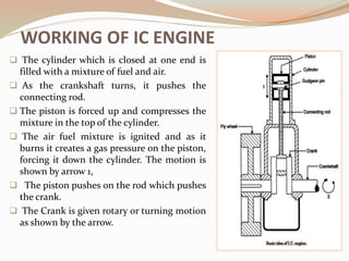
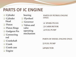
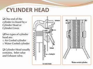
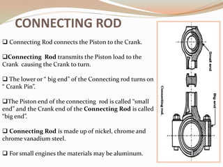
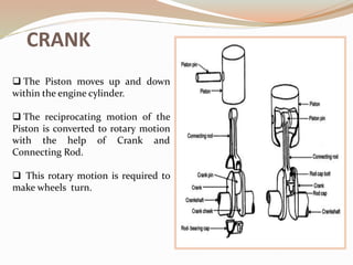
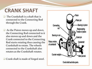
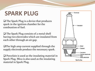
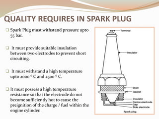
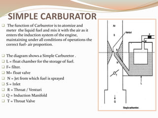
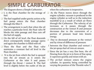
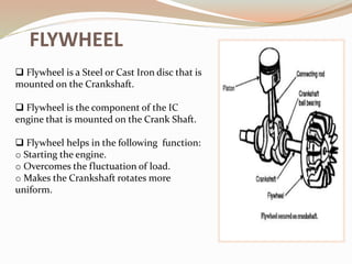
Extracted by:
DEBOLINA MUKHERJEE
From:
IC Engine by
R K RAJPUT
HEAT ENGINES
 Any type of ENGINE or MACHINE which derives heat
energy from the combustion of fuel or any other source
and converts this energy into mechanical work is termed
as HEAT ENGINE.
 HEAT ENGINE is classified into:
 External Combustion Engine.
 Internal Combustion Engine.
INTERNAL COMBUSTION ENGINE
 In Internal Combustion engine, combustion of the
fuel with oxygen of the air occurs within the cylinder of
the engine.
 The internal Combustion engine is grouped into:
 Petrol Engine ( Spark Ignition Engine)
 Diesel Engine ( Compression Ignition Engine)
ADVANTAGES OF RECIPROCATING
INTERNAL COMBUSTION ENGINE
 Overall efficiency is high.
 Greater mechanical simplicity.
 Weight to power ratio is generally low.
 Generally low initial cost.
 Easy starting from cold condition.
 This units are compact and thus require less space.
CLASSIFICATION OF I.C. ENGINE
According to cycle of operation:
 Two Stroke Cycle Engine
 Four Stroke Cycle Engine
According to the cycle of combustion:
 Otto cycle engine ( Combustion at Constant Volume)
 Diesel cycle engine ( Combustion at Constant Pressure)
 Duel combustion or Semi- Diesel cycle
APPLICATION OF IC ENGINE
 Road Vehicles
 Aircraft
 Locomotives
 Construction in civil engineering equipments such as
bull-doser, scraper, power shovels, etc.
 Plumbing sets
 Cinemas
 Hospitals
 Several Industrial Applications
IC Engine can be generally used for :
ENERGY CYCLE – ENERGY BALANCE OF
IC ENGINE
 In an I.C. Engine fuel is fed to the combustion chamber where it burns
in the presence of air and its chemical energy is converted into heat.
All this energy is not available for driving the piston, a portion of
energy is lost through exhaust, coolant and radiation.
The remaining energy is converted into power and is called Indicated
Energy or Indicated Power (I.P.).
The ratio of Indicated Energy to the Fuel energy is called Indicated
Thermal Efficiency.
 The Energy available at the piston
passes through the connecting rod
to the crankshaft.
 In this transmission of energy or
power, there are losses due to
friction, pumping, etc.
 The sum of all those losses, termed
as power is known as frictional
power (F.P.)
 The remaining energy is the useful
mechanical energy known as shaft
energy or brake power (B.P.).
 The ratio of energy at the shaft to
fuel input energy is called Brake
Thermal Efficiency.
 The Ratio of Shaft energy to the
energy available at the piston is
known as Mechanical Efficiency.
ENERGY CYCLE – ENERGY BALANCE OF IC
ENGINE
WORKING OF IC ENGINE
 The cylinder which is closed at one end is
filled with a mixture of fuel and air.
 As the crankshaft turns, it pushes the
connecting rod.
 The piston is forced up and compresses the
mixture in the top of the cylinder.
 The air fuel mixture is ignited and as it
burns it creates a gas pressure on the piston,
forcing it down the cylinder. The motion is
shown by arrow 1,
 The piston pushes on the rod which pushes
the crank.
 The Crank is given rotary or turning motion
as shown by the arrow.
PARTS OF IC ENGINE
 Cylinder
 Cylinder
Head
 Piston
 Piston Rings
 Gudgeon Pin
 Connecting
rod
 Crankshaft
 Crank
 Crank case
 Engine
bearing
 Flywheel
 Governor
 Valves and
valve
operating
mechanism
PARTS OF PETROL ENGINE
ONLY:
 SPARK PLUGS
 CARBURETOR
 FUEL PUMP
PARTS OF DIESEL ENGINE ONLY:
 FUEL PUMP
INJECTOR
CYLINDER
Cylinder contains gas under pressure and guides the Piston.
Cylinder is in direct contact with the product of combustion.
 The ideal type of Piston consists of plain cylindrical barrel in
which the Piston slides.
The upper end of the Cylinder is considered as Combustion or
clearance space in which the combustion of fuel takes place.
The Cylinder is made up of a hard grade Cast Iron and cast in
one piece.
CYLINDER HEAD
 One end of the
cylinder is closed by a
Cylinder Head or
Cylinder Cover.
Two types of cylinder
head are:
o Air Cooled cylinder
o Water Cooled cylinder
 Cylinder Head usually
contains, Inlet value
and Exhaust valve.
PISTON
 Piston is fitted to each cylinder as a face to receive gas pressure and
transmit the thrust to the connecting rod.
 Piston moves up and down within Piston Cylinder. This up and down
motion is called the reciprocating motion.
 Functions of Piston:
o To give an gas tight seal to the cylinder through bore.
o To slide freely.
o To be light.
o To be strong.
 Piston are made of Cast Iron and Aluminum alloy for lightness.
PISTON RINGS
 The Piston must be a fairly loose fit
in the Cylinder.
 If the Piston have a tight fit then it
might expand due to high
temperature and might stick to the
walls of the Cylinder. On the other
hand if there is too much clearance
between the piston and Cylinder
walls, much of the hot gases of
combustion will leak past the Piston.
 To provide a good sealing fit
between the Piston and the Cylinder,
Piston are equipped with Piston
Rings.
Piston rings are usually made of
Cast Iron. Some Piston rings are made
of alloy spring steel.
WORKING OF PISTON RINGS
 The outer surface of the cylindrical Piston have Grooves for fitting the
Piston Rings.
 The design of the Piston Rings are such that they are spitted at one
end. The Piston Rings are fitted into the grooves of the Piston .
 Piston Ring form a good seal between Piston and Cylinder wall.
 When the Piston is installed within the cylinder, the rings are
compressed into the ring grooves of the cylinder, so that the Piston Ring
grooves almost come together and fit into the groove between Piston
and cylinder wall.
 The Piston Rings can expand and contract within the grooves of the
cylinder as they get heated and cooled and can form a seal between the
Piston and Cylinder wall.
WORKING OF PISTON RINGS
 The diagram shows how the Piston ring
works to hold the compression and
combustion pressure.
 The arrows shows the pressure above the
Piston and the Cylinder wall.
 The Piston rings ensure good seal
between the Piston and the Cylinder even at
high pressure.
CONNECTING ROD
 Connecting Rod connects the Piston to the Crank.
Connecting Rod transmits the Piston load to the
Crank causing the Crank to turn.
 The lower or “ big end” of the Connecting rod turns on
“ Crank Pin”.
The Piston end of the connecting rod is called “small
end” and the Crank end of the Connecting Rod is called
“big end”.
 Connecting Rod is made up of nickel, chrome and
chrome vanadium steel.
 For small engines the materials may be aluminum.
CRANK
 The Piston moves up and down
within the engine cylinder.
 The reciprocating motion of the
Piston is converted to rotary motion
with the help of Crank and
Connecting Rod.
 This rotary motion is required to
make wheels turn.
CRANK SHAFT
 The Crankshaft is a shaft that is
connected to the Connecting Rod
through the Crank.
 As the Piston moves up and down,
the Connecting Rod connected to it
also moves up and down and the
Crank connected to the Connecting
Rod starts rotating thus causing the
Crankshaft to rotate. The wheels
connected to the Crankshaft also
rotates as the Crankshaft rotates.
 Crank shaft is made of forged steel.
SPARK PLUG
 The Spark Plug is a device that produces
spark in the ignition chamber for the
combustion of fuel.
 The Spark Plug consists of a metal shell
having two electrodes which are insulated from
each other through an air gap.
The high amp current supplied through the
supply electrode produce the necessary spark.
 Porcelain is used as the insulating material in
Spark Plug. Mica is also used as the insulating
material in Spark Plug.
 Spark Plug must withstand pressure upto
55 bar.
 It must provide suitable insulation
between two electrodes to prevent short
circuiting.
 It must withstand a high temperature
upto 2000 ⁰ C and 2500 ⁰ C.
 It must possess a high temperature
resistance so that the electrode do not
become sufficiently hot to cause the
preignition of the charge / fuel within the
engine cylinder.
QUALITY REQUIRES IN SPARK PLUG
SIMPLE CARBURATOR
 The function of Carburetor is to atomize and
meter the liquid fuel and mix it with the air as it
enters the induction system of the engine,
maintaining under all conditions of operations the
correct fuel- air proportion.
 The diagram shows a Simple Carburetor .
 L = float chamber for the storage of fuel.
 F= filter.
 M= float valve
 N = Jet from which fuel is sprayed
 S = Inlet
 R = Throat / Venturi
 Q = Induction Manifold
 T = Throat Valve
SIMPLE CARBURATOR
 The diagram shows a Simple Carburetor .
 L is the float chamber for the storage of
fuel.
 The fuel supplied under gravity action or by
fuel pump enters the float chamber
through the filter F.
 The arrangement is such that when the oil
reaches a particular level, the float valve M
blocks the inlet passage and thus cuts off
the fuel oil supply.
 On the fall of oil level, the float descends
down consequently intake passage opens
and again the chamber is filled with oil.
 Then the float and the float valve
maintains a constant fuel oil level in the
float chamber.
 N is the jet from which the fuel is sprayed
into the air stream as it enters the
Carburetor at the inlet S and passes
through the throat / venturi R. The fuel
level is slightly below the outlet of the jet
when the carburetor is inoperative.
 As the Piston moves down through the
engine cylinder, vacuum is produced in the
engine cylinder as well as in the induction
manifold Q as a result of which air flows
through the Carburetor. The velocity of air
increases as it passes through the
construction at the venturi R and pressure
decreases due to the conversion of a
portion of pressure head into kinetic
energy.
 Due to decreased pressure at the venturi
and by virtue of difference of pressure
( between the float chamber and venturi )
the jet sprays fuel oil into air stream.
 Since the jet has a very fine bore, the oil
flowing from the jet is in form of fine spray,
it vaporizes quickly and mixes with air.
 The air-fuel mixture enters the engine
cylinder, its quantity being controlled by
varying the position of the Throttle valve T.
FLYWHEEL
 Flywheel is a Steel or Cast Iron disc that is
mounted on the Crankshaft.
 Flywheel is the component of the IC
engine that is mounted on the Crank Shaft.
 Flywheel helps in the following function:
o Starting the engine.
o Overcomes the fluctuation of load.
o Makes the Crankshaft rotates more
uniform.
GOVERNOR
 Governor is a device that controls the output of a machine
or engine by regulating the Working fluid supplied i.e
controlling the supply of fuel.
 Types of GOVERNOR:
 Centrifugal Governor
 Inertia Governor

Internal combustion engine 1

  • 1.
  • 2.
    HEAT ENGINES  Anytype of ENGINE or MACHINE which derives heat energy from the combustion of fuel or any other source and converts this energy into mechanical work is termed as HEAT ENGINE.  HEAT ENGINE is classified into:  External Combustion Engine.  Internal Combustion Engine.
  • 3.
    INTERNAL COMBUSTION ENGINE In Internal Combustion engine, combustion of the fuel with oxygen of the air occurs within the cylinder of the engine.  The internal Combustion engine is grouped into:  Petrol Engine ( Spark Ignition Engine)  Diesel Engine ( Compression Ignition Engine)
  • 4.
    ADVANTAGES OF RECIPROCATING INTERNALCOMBUSTION ENGINE  Overall efficiency is high.  Greater mechanical simplicity.  Weight to power ratio is generally low.  Generally low initial cost.  Easy starting from cold condition.  This units are compact and thus require less space.
  • 5.
    CLASSIFICATION OF I.C.ENGINE According to cycle of operation:  Two Stroke Cycle Engine  Four Stroke Cycle Engine According to the cycle of combustion:  Otto cycle engine ( Combustion at Constant Volume)  Diesel cycle engine ( Combustion at Constant Pressure)  Duel combustion or Semi- Diesel cycle
  • 6.
    APPLICATION OF ICENGINE  Road Vehicles  Aircraft  Locomotives  Construction in civil engineering equipments such as bull-doser, scraper, power shovels, etc.  Plumbing sets  Cinemas  Hospitals  Several Industrial Applications IC Engine can be generally used for :
  • 7.
    ENERGY CYCLE –ENERGY BALANCE OF IC ENGINE  In an I.C. Engine fuel is fed to the combustion chamber where it burns in the presence of air and its chemical energy is converted into heat. All this energy is not available for driving the piston, a portion of energy is lost through exhaust, coolant and radiation. The remaining energy is converted into power and is called Indicated Energy or Indicated Power (I.P.). The ratio of Indicated Energy to the Fuel energy is called Indicated Thermal Efficiency.
  • 8.
     The Energyavailable at the piston passes through the connecting rod to the crankshaft.  In this transmission of energy or power, there are losses due to friction, pumping, etc.  The sum of all those losses, termed as power is known as frictional power (F.P.)  The remaining energy is the useful mechanical energy known as shaft energy or brake power (B.P.).  The ratio of energy at the shaft to fuel input energy is called Brake Thermal Efficiency.  The Ratio of Shaft energy to the energy available at the piston is known as Mechanical Efficiency. ENERGY CYCLE – ENERGY BALANCE OF IC ENGINE
  • 9.
    WORKING OF ICENGINE  The cylinder which is closed at one end is filled with a mixture of fuel and air.  As the crankshaft turns, it pushes the connecting rod.  The piston is forced up and compresses the mixture in the top of the cylinder.  The air fuel mixture is ignited and as it burns it creates a gas pressure on the piston, forcing it down the cylinder. The motion is shown by arrow 1,  The piston pushes on the rod which pushes the crank.  The Crank is given rotary or turning motion as shown by the arrow.
  • 10.
    PARTS OF ICENGINE  Cylinder  Cylinder Head  Piston  Piston Rings  Gudgeon Pin  Connecting rod  Crankshaft  Crank  Crank case  Engine bearing  Flywheel  Governor  Valves and valve operating mechanism PARTS OF PETROL ENGINE ONLY:  SPARK PLUGS  CARBURETOR  FUEL PUMP PARTS OF DIESEL ENGINE ONLY:  FUEL PUMP INJECTOR
  • 11.
    CYLINDER Cylinder contains gasunder pressure and guides the Piston. Cylinder is in direct contact with the product of combustion.  The ideal type of Piston consists of plain cylindrical barrel in which the Piston slides. The upper end of the Cylinder is considered as Combustion or clearance space in which the combustion of fuel takes place. The Cylinder is made up of a hard grade Cast Iron and cast in one piece.
  • 12.
    CYLINDER HEAD  Oneend of the cylinder is closed by a Cylinder Head or Cylinder Cover. Two types of cylinder head are: o Air Cooled cylinder o Water Cooled cylinder  Cylinder Head usually contains, Inlet value and Exhaust valve.
  • 13.
    PISTON  Piston isfitted to each cylinder as a face to receive gas pressure and transmit the thrust to the connecting rod.  Piston moves up and down within Piston Cylinder. This up and down motion is called the reciprocating motion.  Functions of Piston: o To give an gas tight seal to the cylinder through bore. o To slide freely. o To be light. o To be strong.  Piston are made of Cast Iron and Aluminum alloy for lightness.
  • 14.
    PISTON RINGS  ThePiston must be a fairly loose fit in the Cylinder.  If the Piston have a tight fit then it might expand due to high temperature and might stick to the walls of the Cylinder. On the other hand if there is too much clearance between the piston and Cylinder walls, much of the hot gases of combustion will leak past the Piston.  To provide a good sealing fit between the Piston and the Cylinder, Piston are equipped with Piston Rings. Piston rings are usually made of Cast Iron. Some Piston rings are made of alloy spring steel.
  • 15.
    WORKING OF PISTONRINGS  The outer surface of the cylindrical Piston have Grooves for fitting the Piston Rings.  The design of the Piston Rings are such that they are spitted at one end. The Piston Rings are fitted into the grooves of the Piston .  Piston Ring form a good seal between Piston and Cylinder wall.  When the Piston is installed within the cylinder, the rings are compressed into the ring grooves of the cylinder, so that the Piston Ring grooves almost come together and fit into the groove between Piston and cylinder wall.  The Piston Rings can expand and contract within the grooves of the cylinder as they get heated and cooled and can form a seal between the Piston and Cylinder wall.
  • 16.
    WORKING OF PISTONRINGS  The diagram shows how the Piston ring works to hold the compression and combustion pressure.  The arrows shows the pressure above the Piston and the Cylinder wall.  The Piston rings ensure good seal between the Piston and the Cylinder even at high pressure.
  • 17.
    CONNECTING ROD  ConnectingRod connects the Piston to the Crank. Connecting Rod transmits the Piston load to the Crank causing the Crank to turn.  The lower or “ big end” of the Connecting rod turns on “ Crank Pin”. The Piston end of the connecting rod is called “small end” and the Crank end of the Connecting Rod is called “big end”.  Connecting Rod is made up of nickel, chrome and chrome vanadium steel.  For small engines the materials may be aluminum.
  • 18.
    CRANK  The Pistonmoves up and down within the engine cylinder.  The reciprocating motion of the Piston is converted to rotary motion with the help of Crank and Connecting Rod.  This rotary motion is required to make wheels turn.
  • 19.
    CRANK SHAFT  TheCrankshaft is a shaft that is connected to the Connecting Rod through the Crank.  As the Piston moves up and down, the Connecting Rod connected to it also moves up and down and the Crank connected to the Connecting Rod starts rotating thus causing the Crankshaft to rotate. The wheels connected to the Crankshaft also rotates as the Crankshaft rotates.  Crank shaft is made of forged steel.
  • 20.
    SPARK PLUG  TheSpark Plug is a device that produces spark in the ignition chamber for the combustion of fuel.  The Spark Plug consists of a metal shell having two electrodes which are insulated from each other through an air gap. The high amp current supplied through the supply electrode produce the necessary spark.  Porcelain is used as the insulating material in Spark Plug. Mica is also used as the insulating material in Spark Plug.
  • 21.
     Spark Plugmust withstand pressure upto 55 bar.  It must provide suitable insulation between two electrodes to prevent short circuiting.  It must withstand a high temperature upto 2000 ⁰ C and 2500 ⁰ C.  It must possess a high temperature resistance so that the electrode do not become sufficiently hot to cause the preignition of the charge / fuel within the engine cylinder. QUALITY REQUIRES IN SPARK PLUG
  • 22.
    SIMPLE CARBURATOR  Thefunction of Carburetor is to atomize and meter the liquid fuel and mix it with the air as it enters the induction system of the engine, maintaining under all conditions of operations the correct fuel- air proportion.  The diagram shows a Simple Carburetor .  L = float chamber for the storage of fuel.  F= filter.  M= float valve  N = Jet from which fuel is sprayed  S = Inlet  R = Throat / Venturi  Q = Induction Manifold  T = Throat Valve
  • 23.
    SIMPLE CARBURATOR  Thediagram shows a Simple Carburetor .  L is the float chamber for the storage of fuel.  The fuel supplied under gravity action or by fuel pump enters the float chamber through the filter F.  The arrangement is such that when the oil reaches a particular level, the float valve M blocks the inlet passage and thus cuts off the fuel oil supply.  On the fall of oil level, the float descends down consequently intake passage opens and again the chamber is filled with oil.  Then the float and the float valve maintains a constant fuel oil level in the float chamber.  N is the jet from which the fuel is sprayed into the air stream as it enters the Carburetor at the inlet S and passes through the throat / venturi R. The fuel level is slightly below the outlet of the jet when the carburetor is inoperative.  As the Piston moves down through the engine cylinder, vacuum is produced in the engine cylinder as well as in the induction manifold Q as a result of which air flows through the Carburetor. The velocity of air increases as it passes through the construction at the venturi R and pressure decreases due to the conversion of a portion of pressure head into kinetic energy.  Due to decreased pressure at the venturi and by virtue of difference of pressure ( between the float chamber and venturi ) the jet sprays fuel oil into air stream.  Since the jet has a very fine bore, the oil flowing from the jet is in form of fine spray, it vaporizes quickly and mixes with air.  The air-fuel mixture enters the engine cylinder, its quantity being controlled by varying the position of the Throttle valve T.
  • 24.
    FLYWHEEL  Flywheel isa Steel or Cast Iron disc that is mounted on the Crankshaft.  Flywheel is the component of the IC engine that is mounted on the Crank Shaft.  Flywheel helps in the following function: o Starting the engine. o Overcomes the fluctuation of load. o Makes the Crankshaft rotates more uniform.
  • 25.
    GOVERNOR  Governor isa device that controls the output of a machine or engine by regulating the Working fluid supplied i.e controlling the supply of fuel.  Types of GOVERNOR:  Centrifugal Governor  Inertia Governor