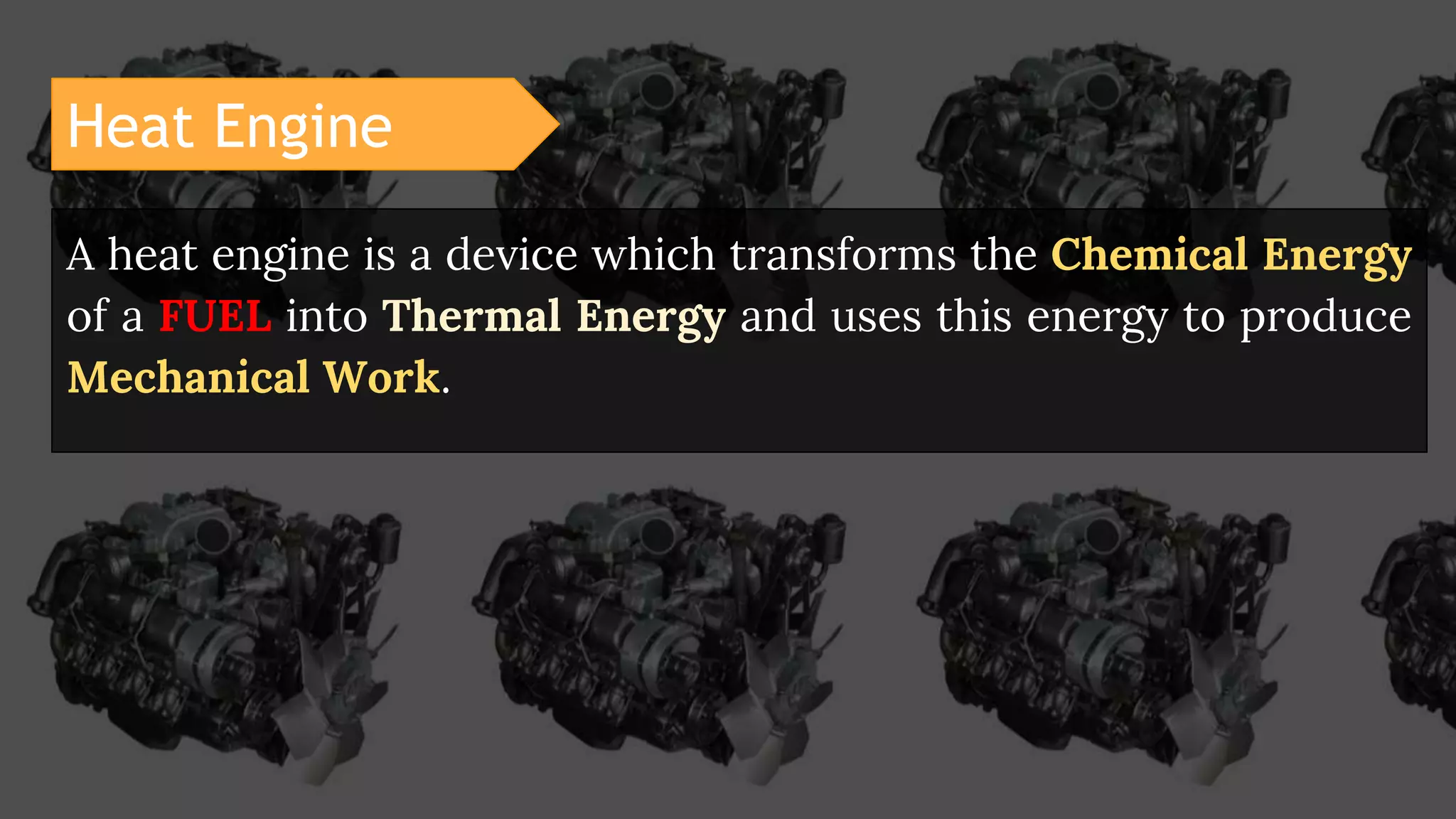
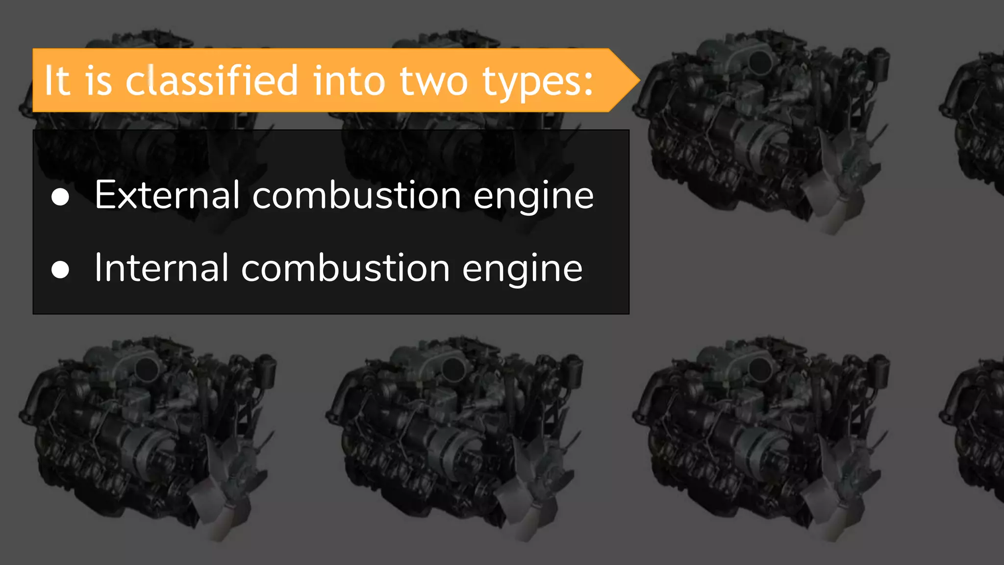
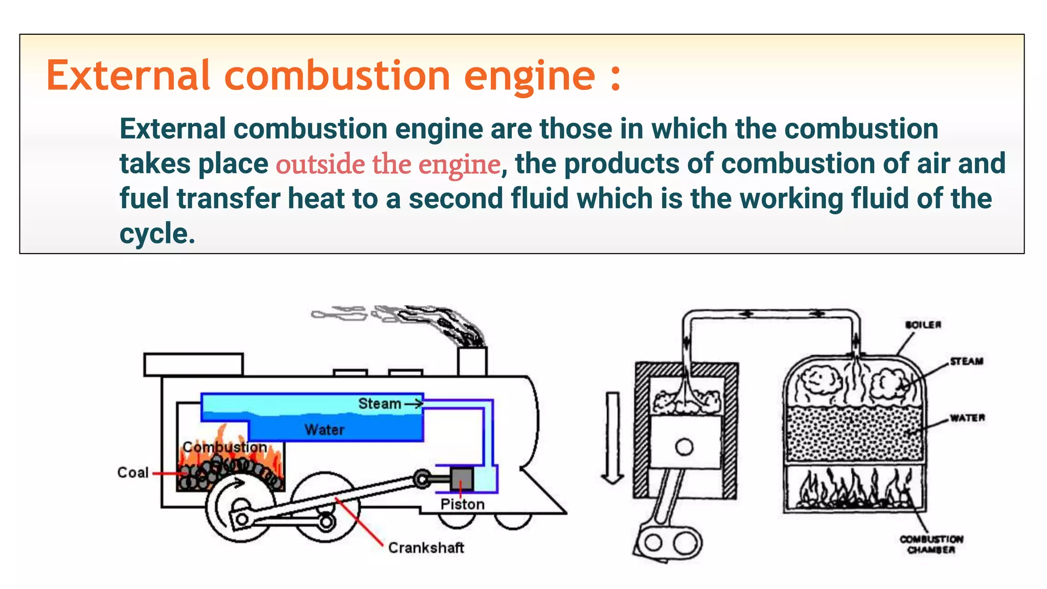
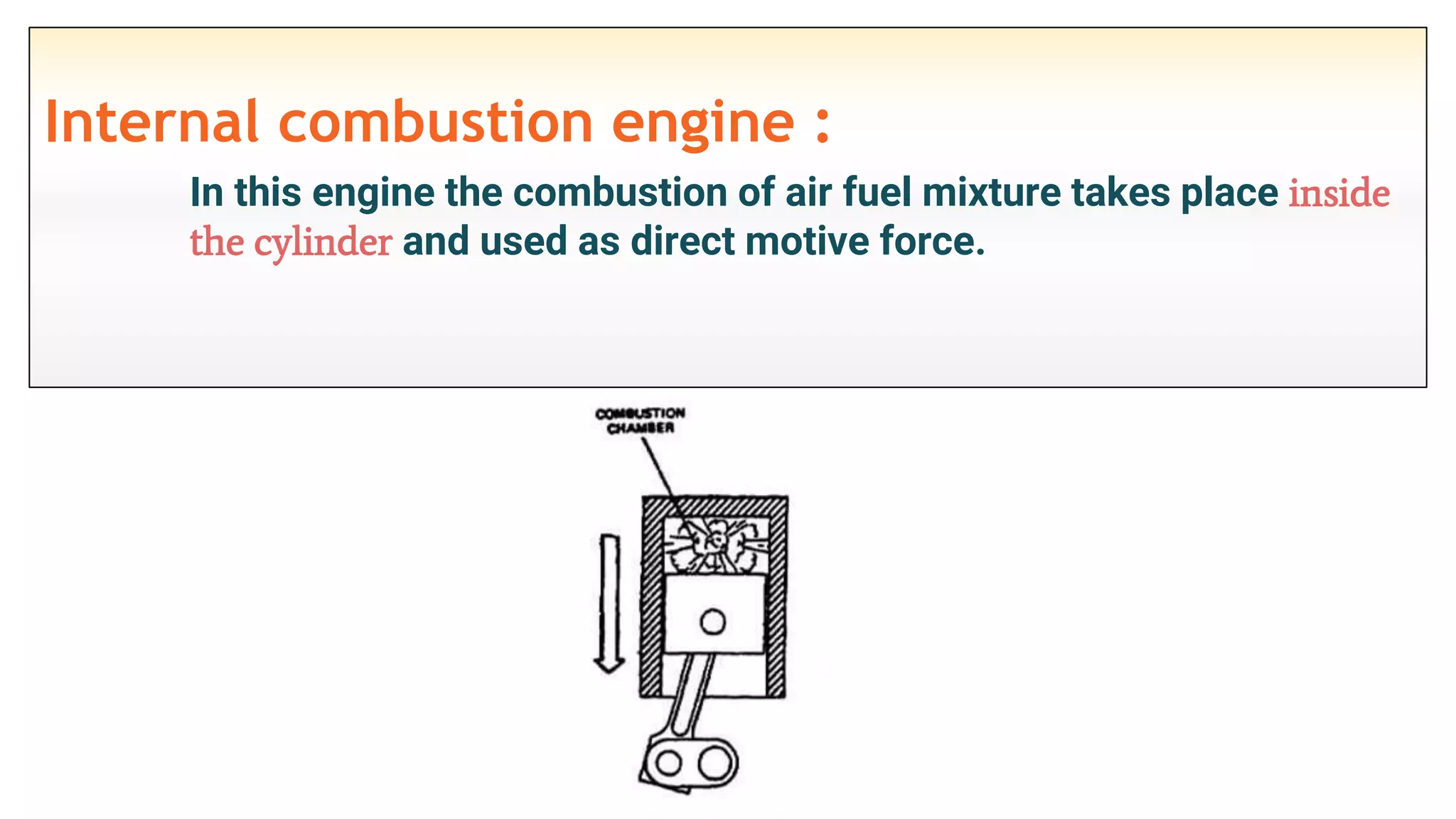
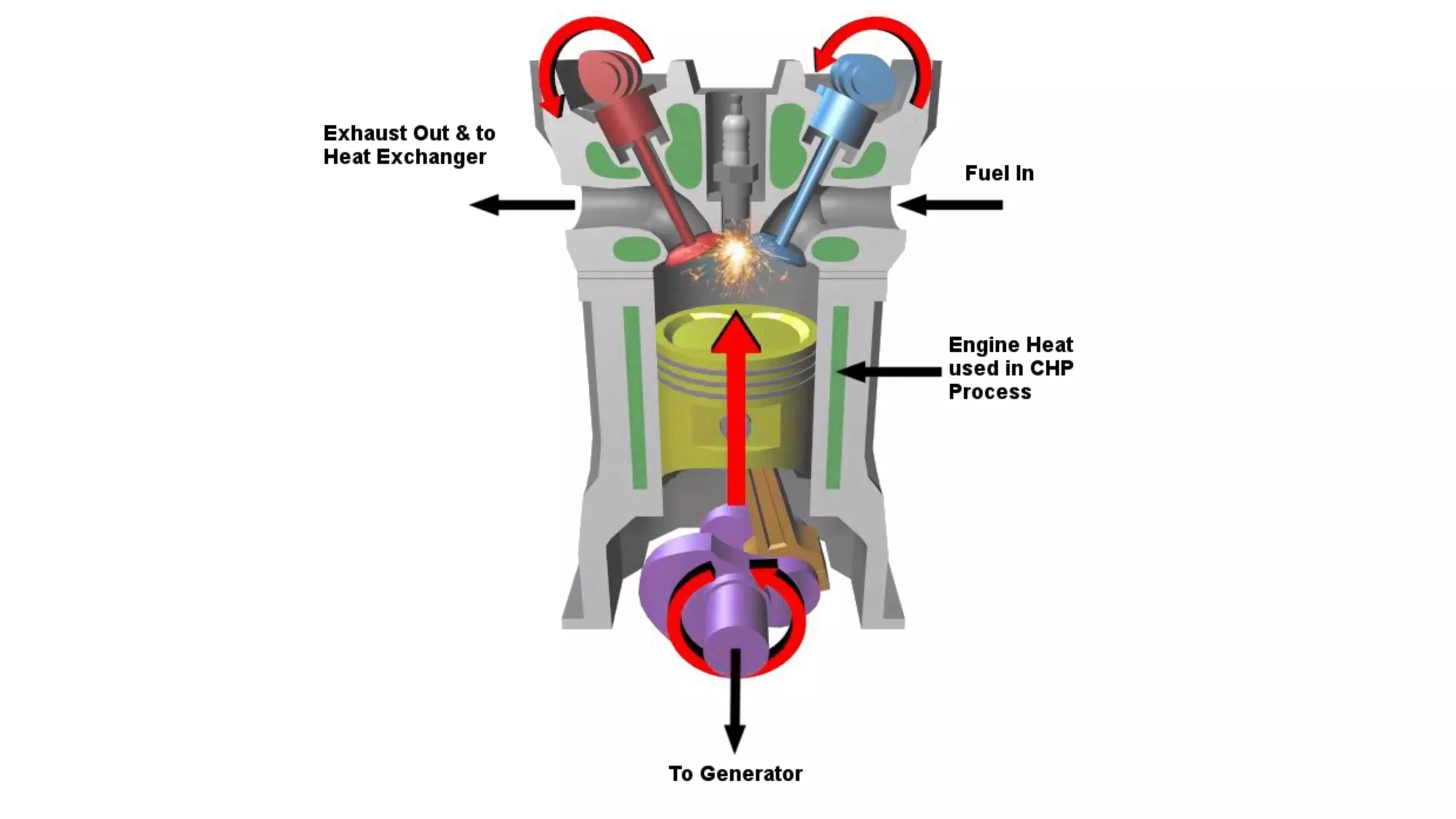
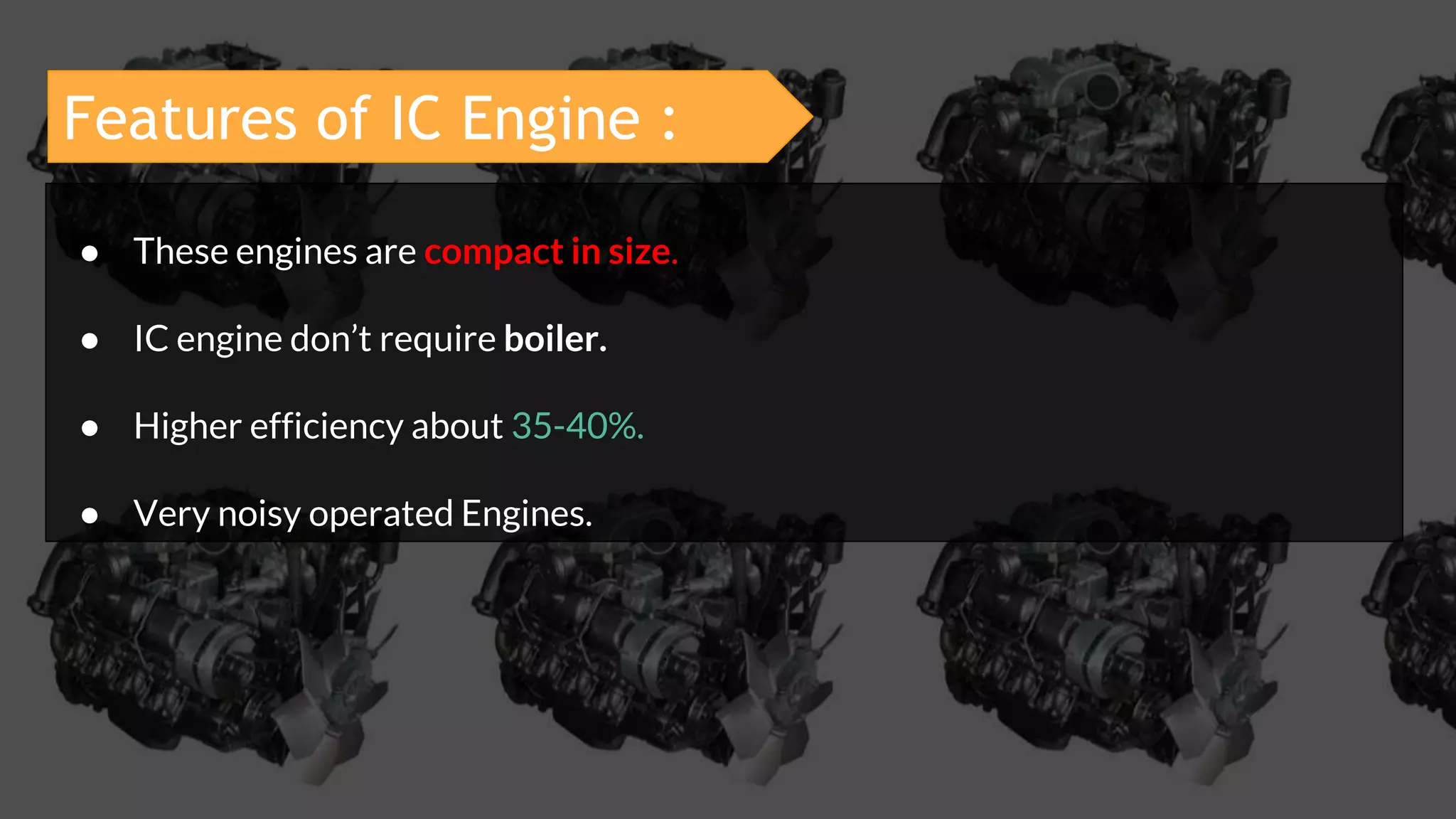
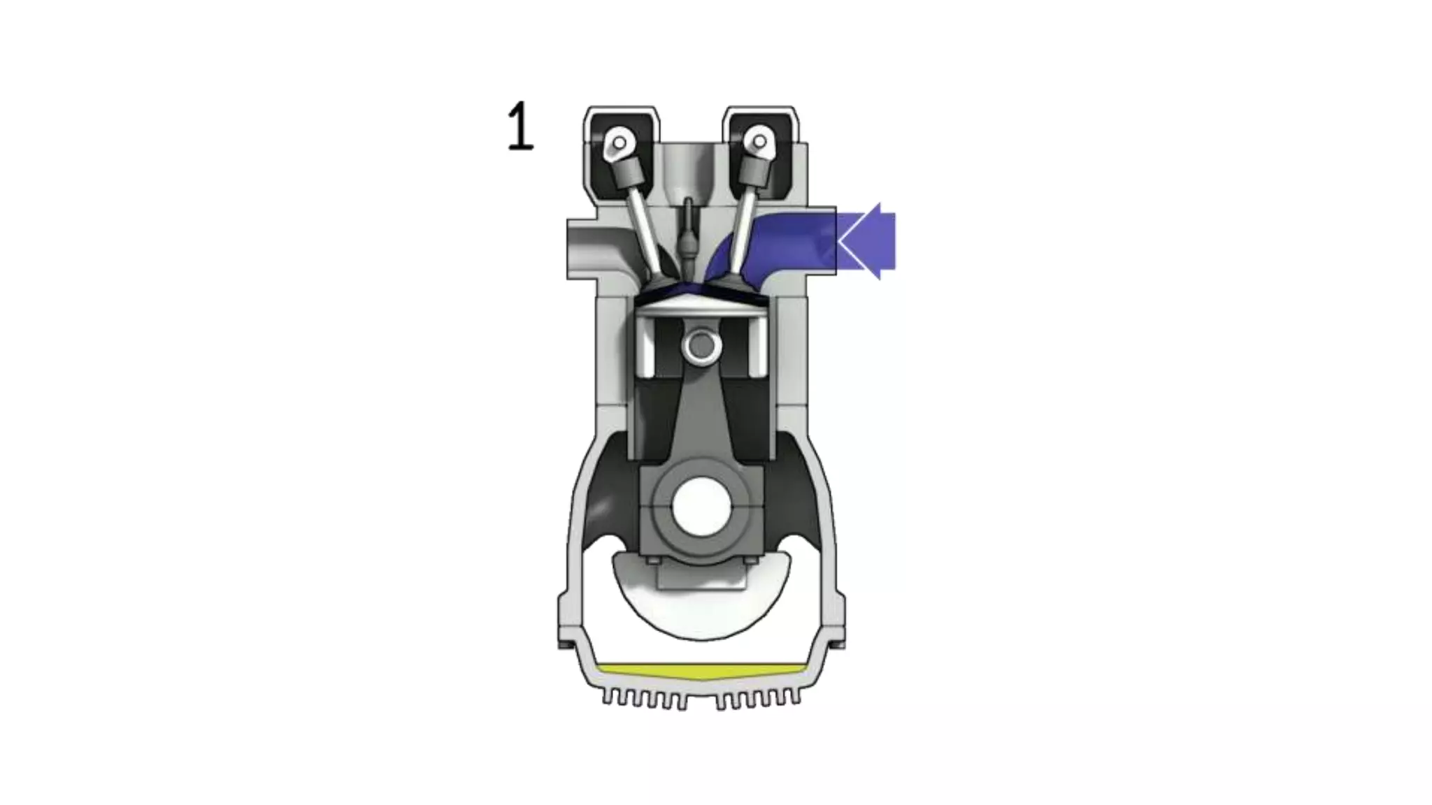
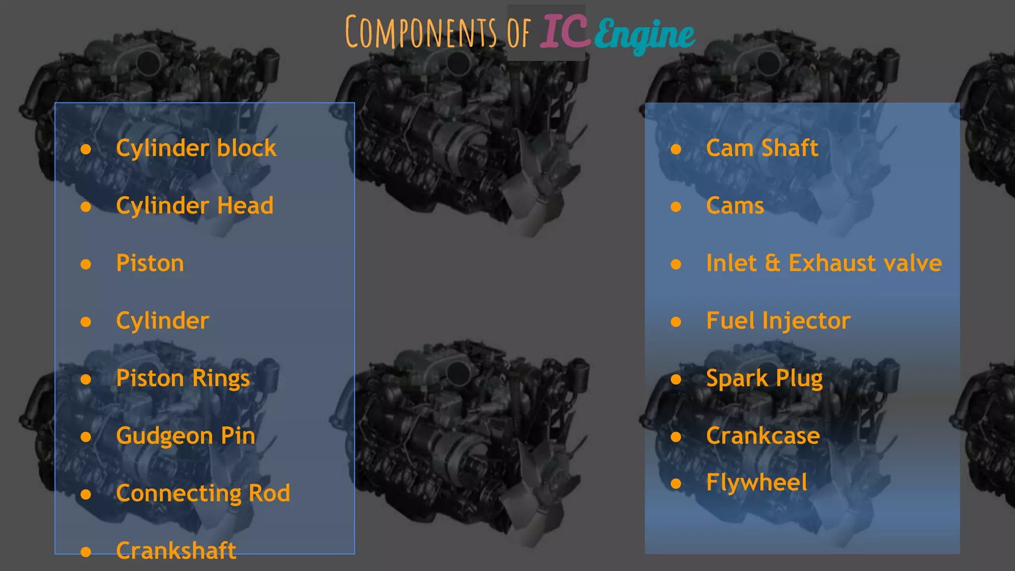
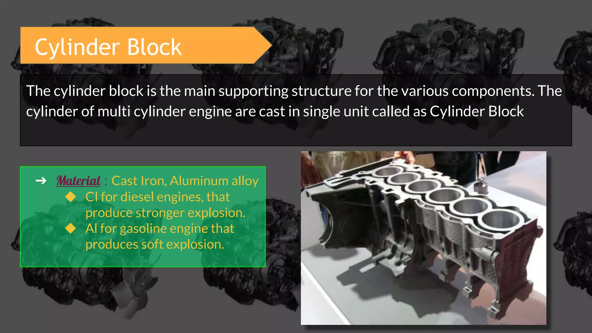
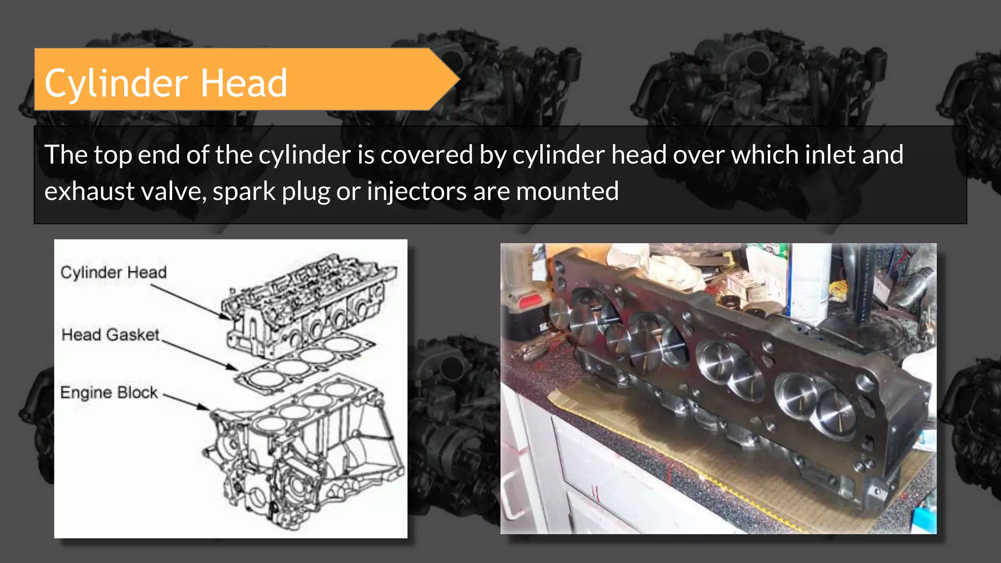
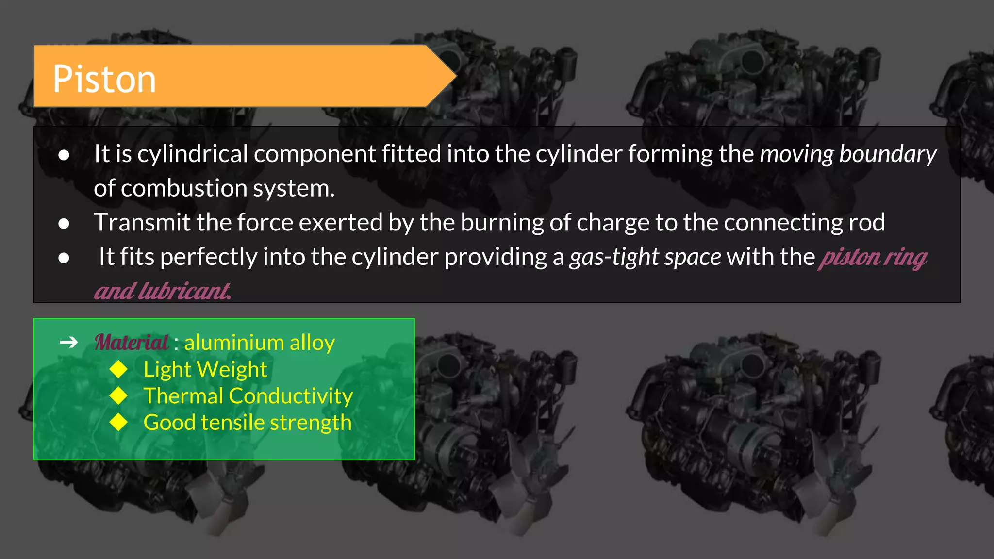
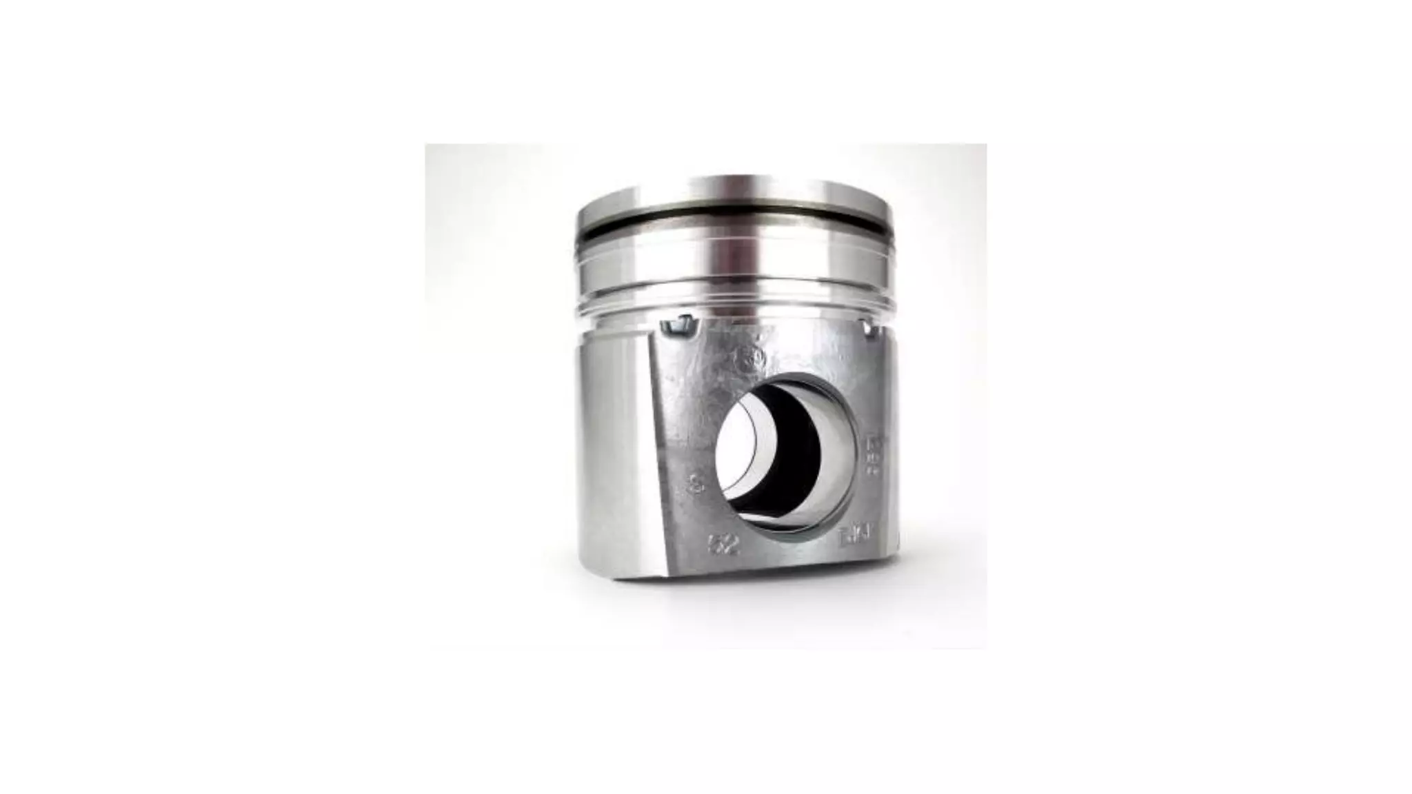
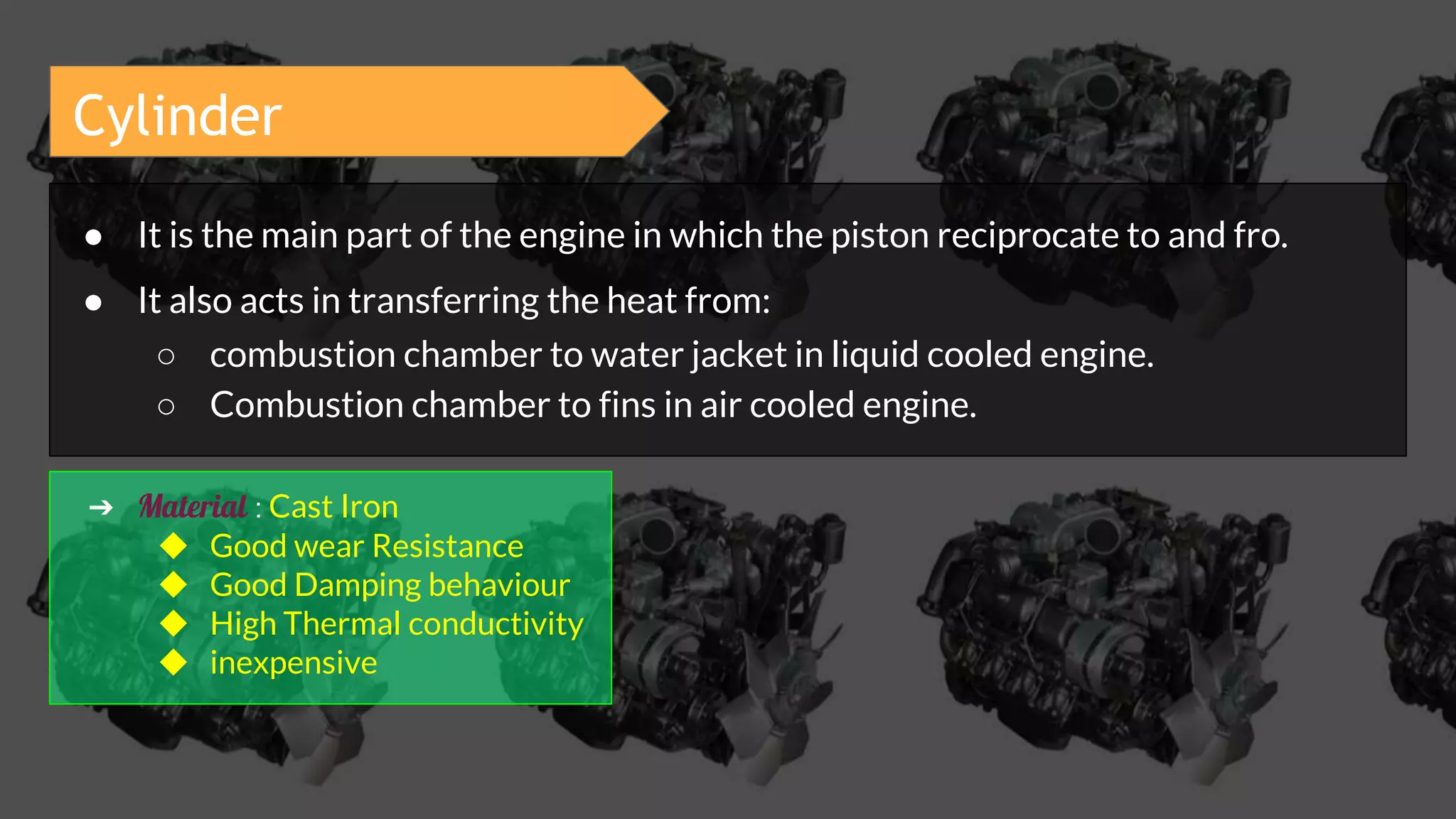
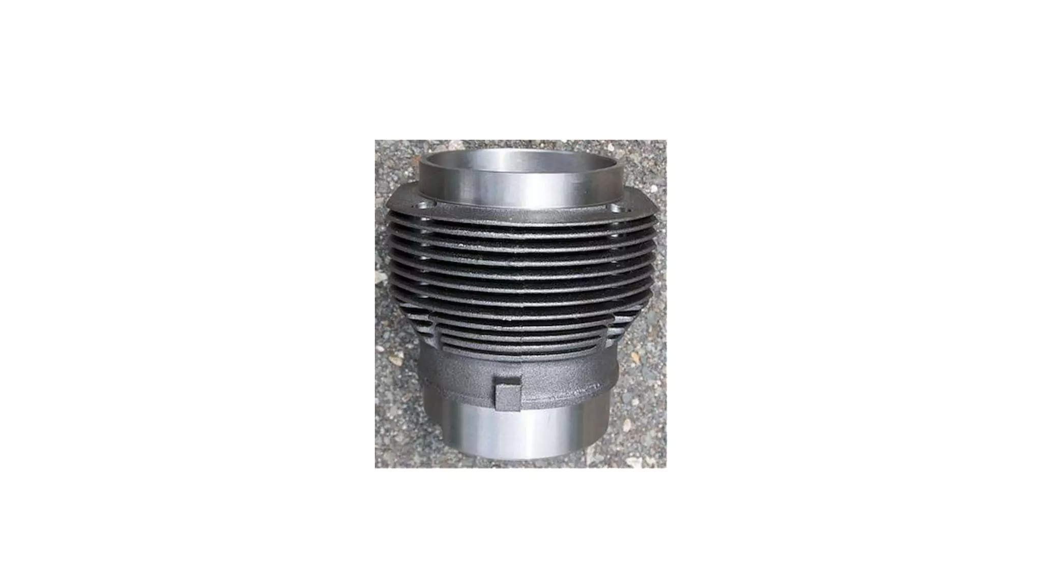
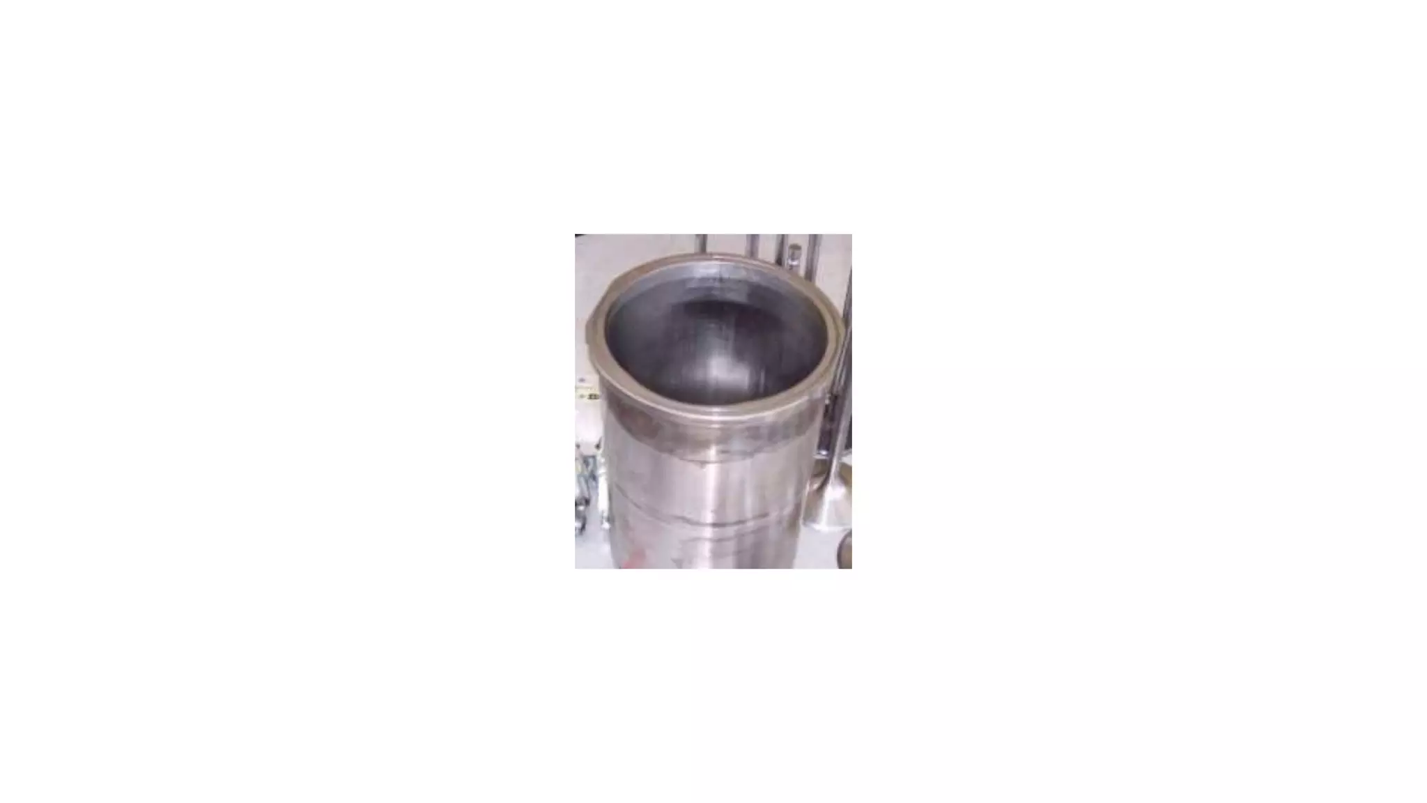
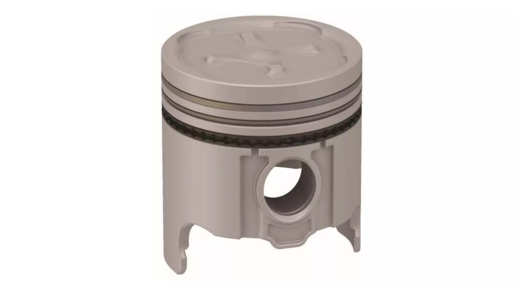
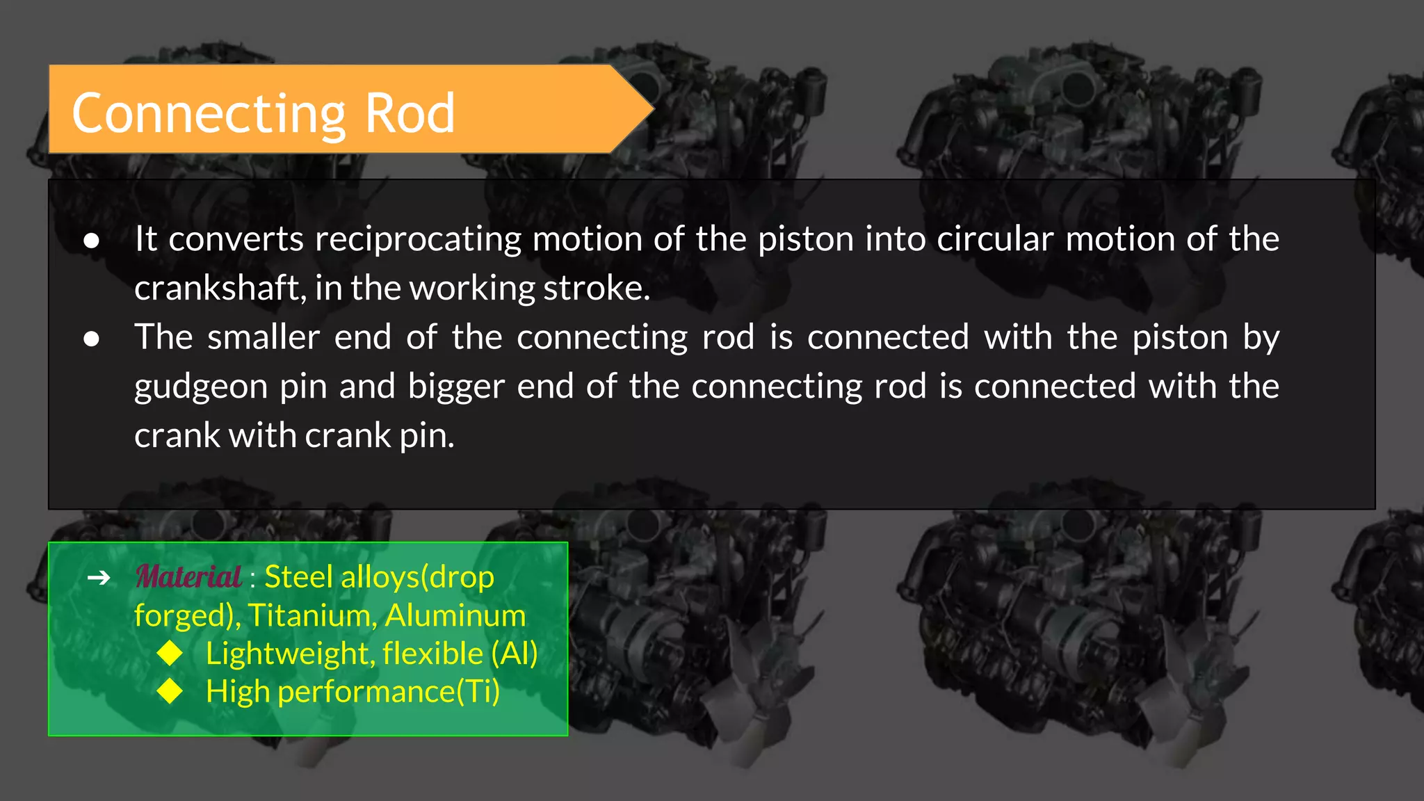
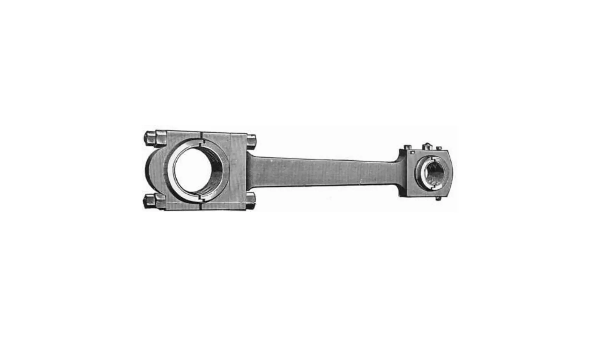
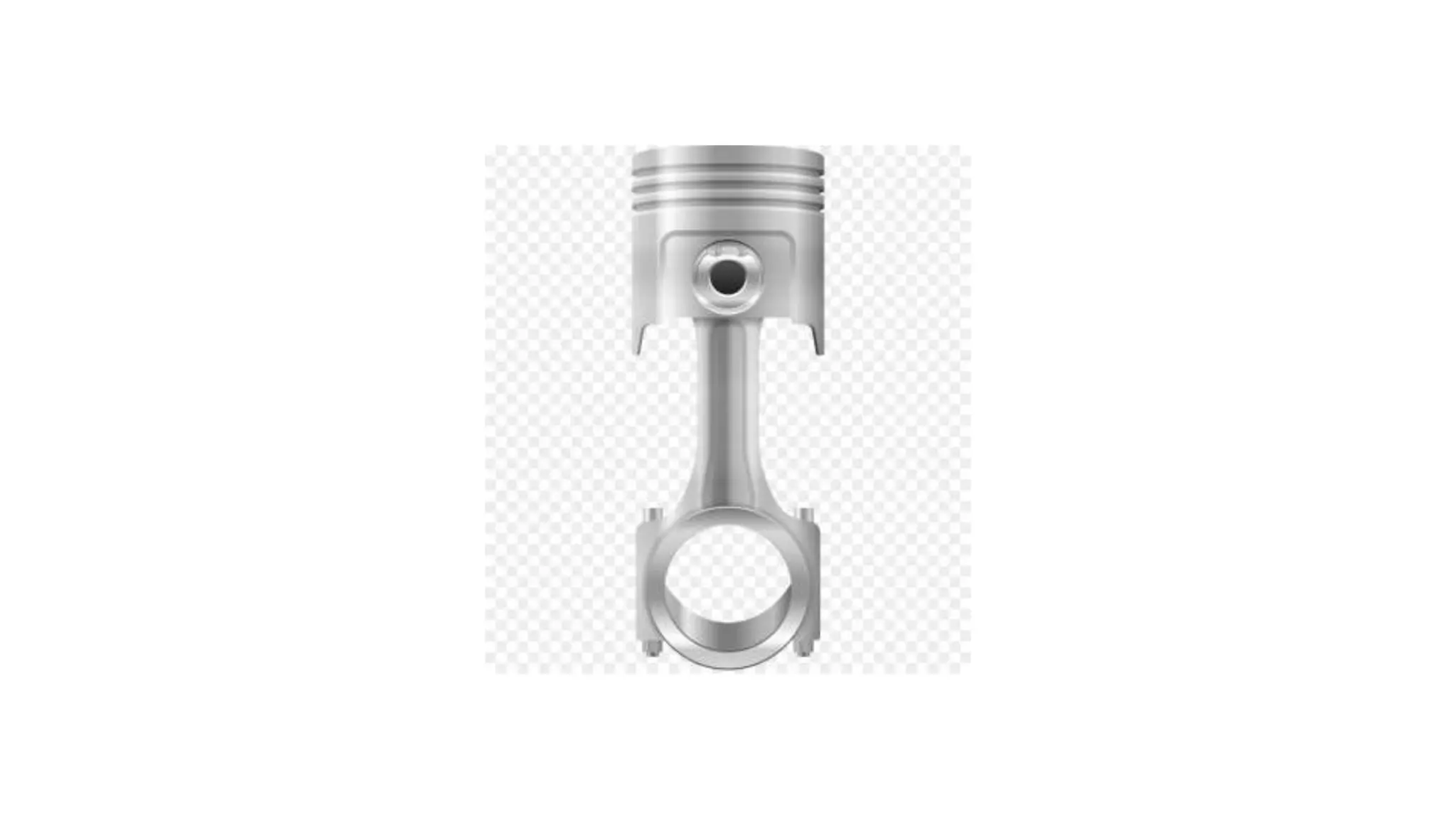
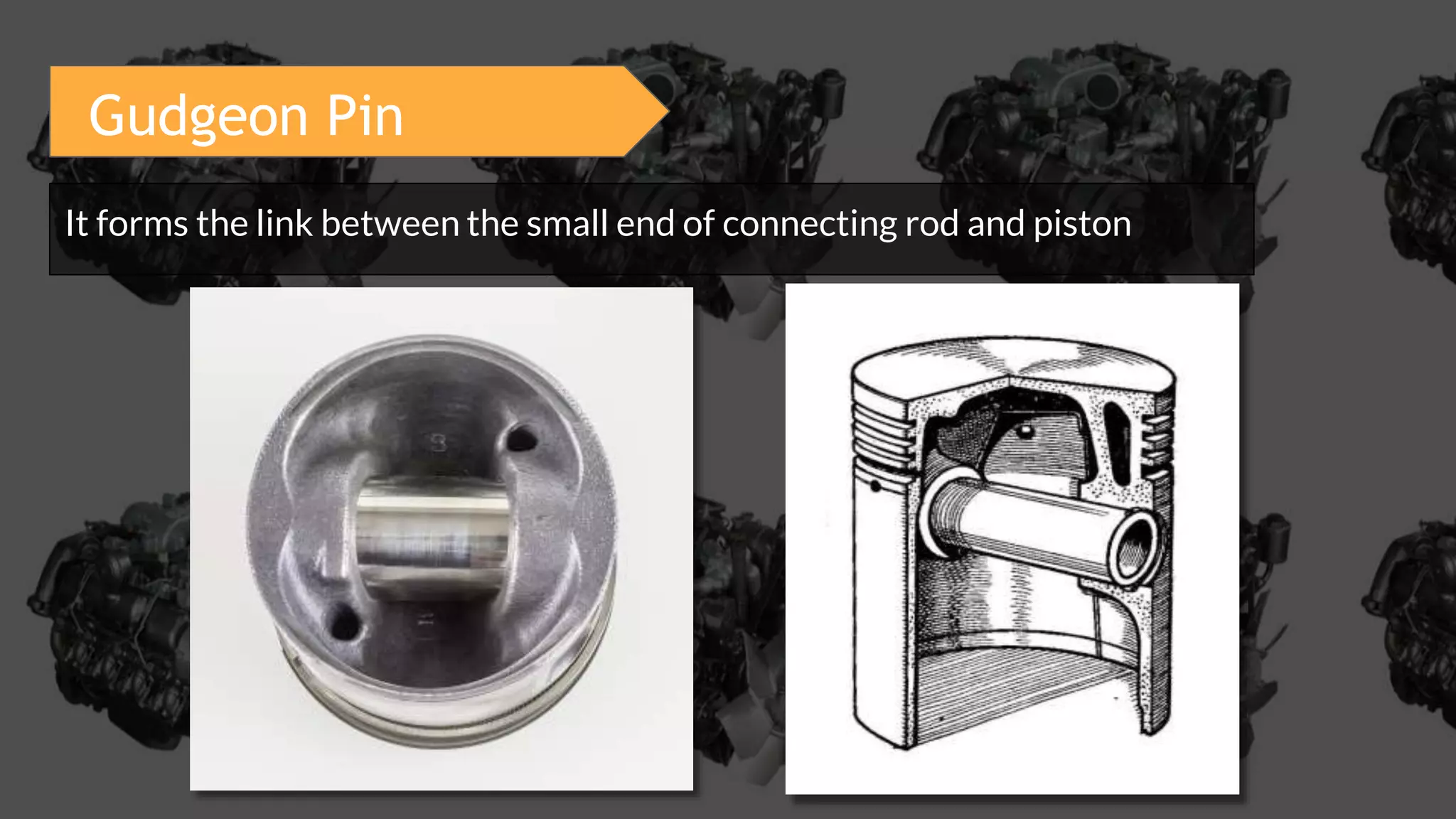
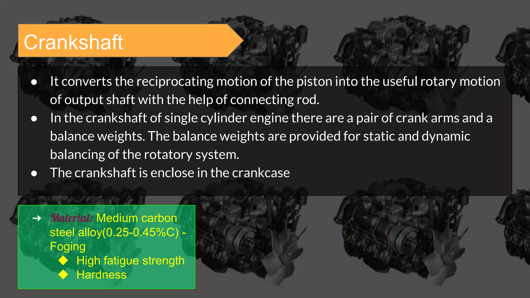
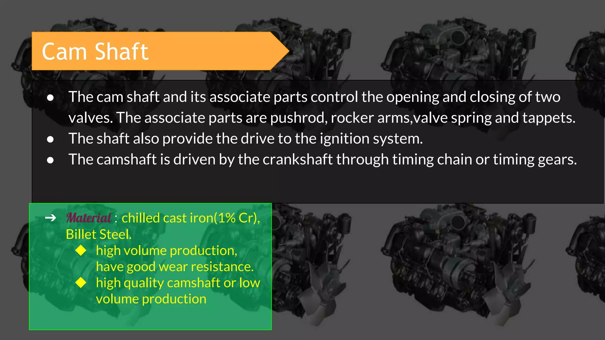
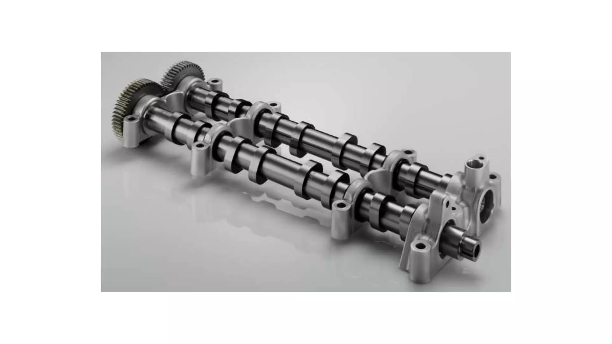
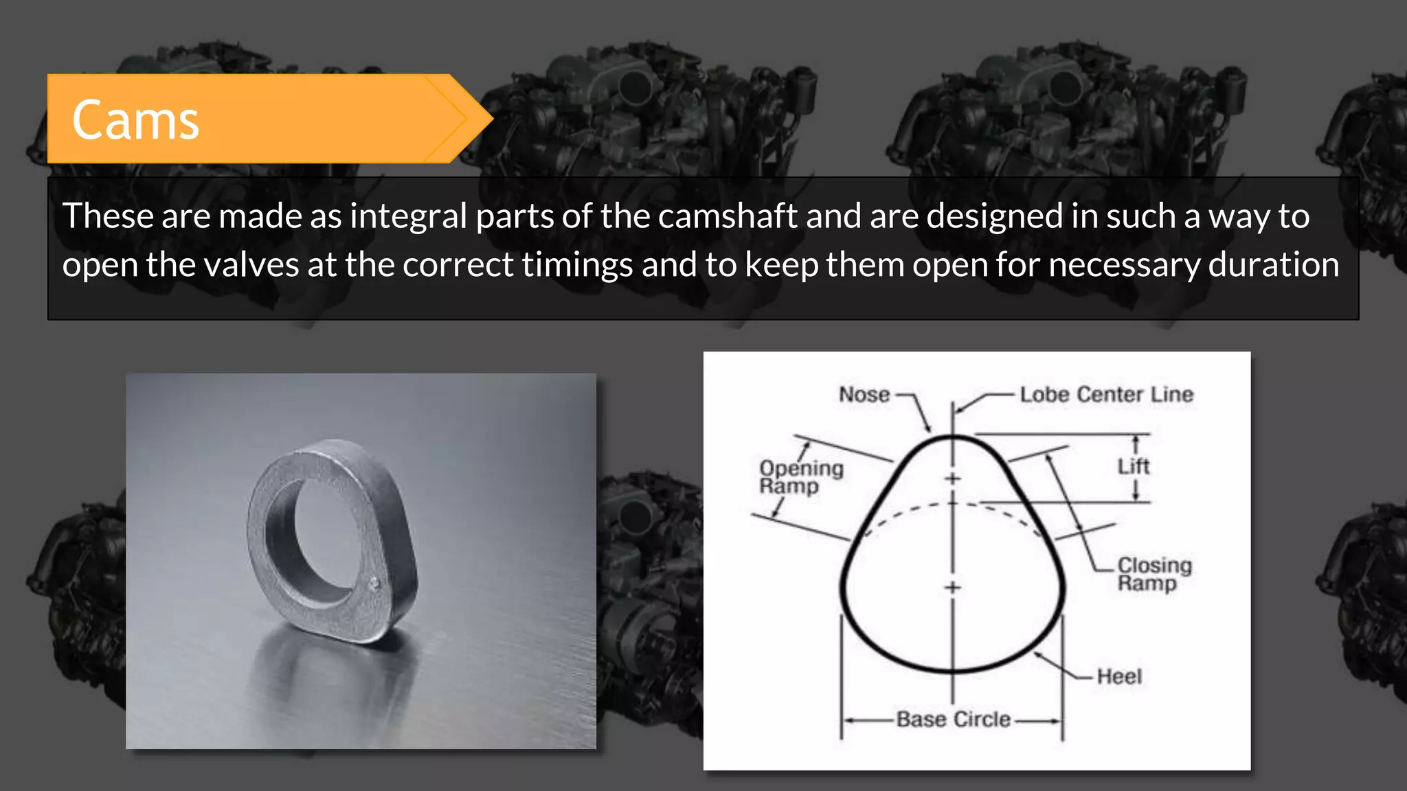
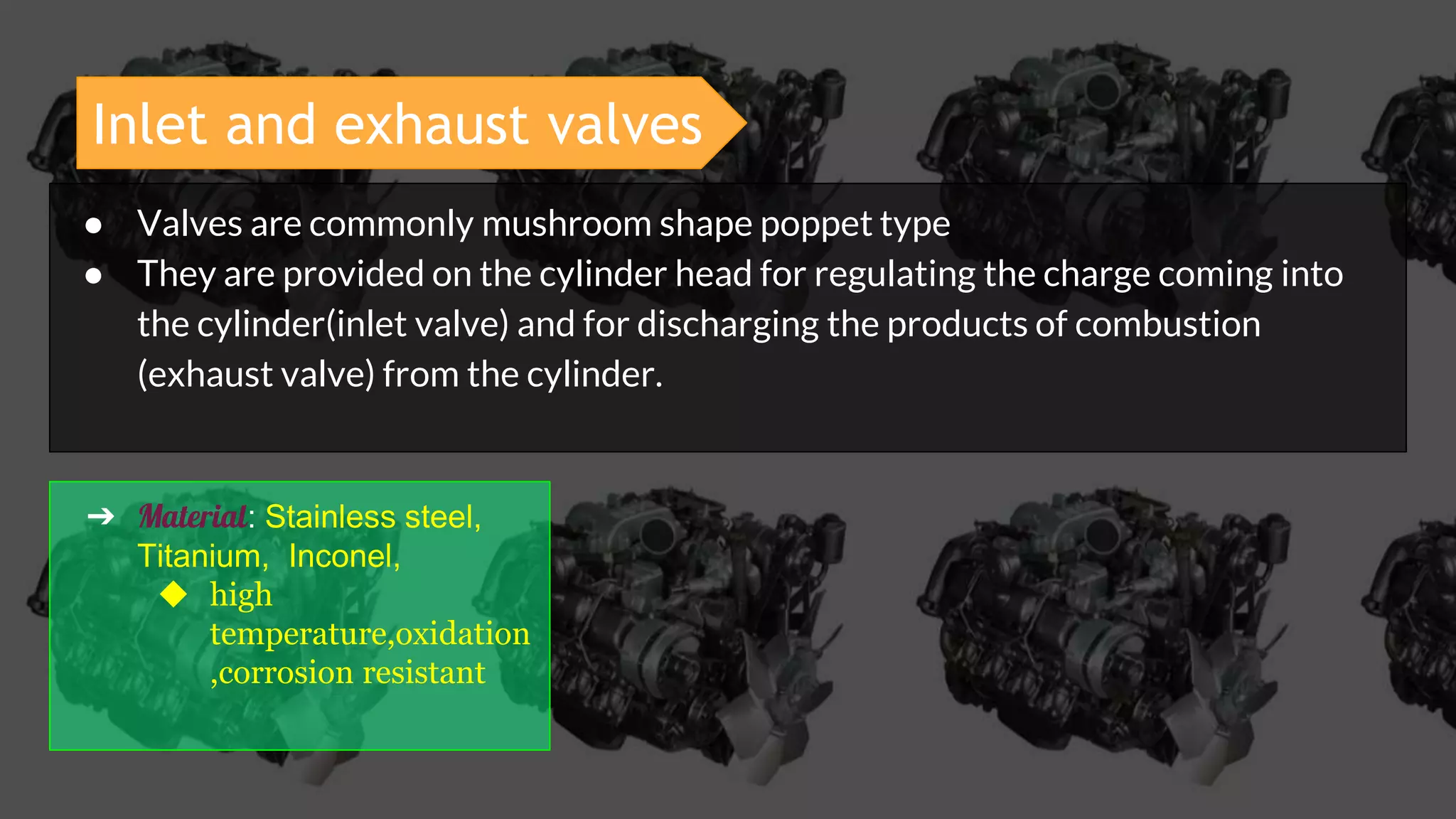
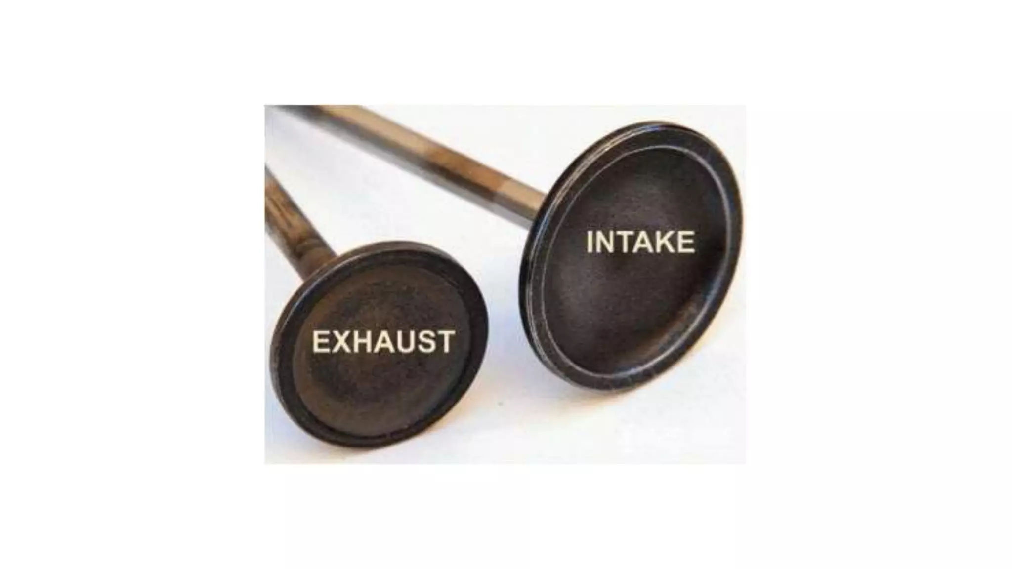
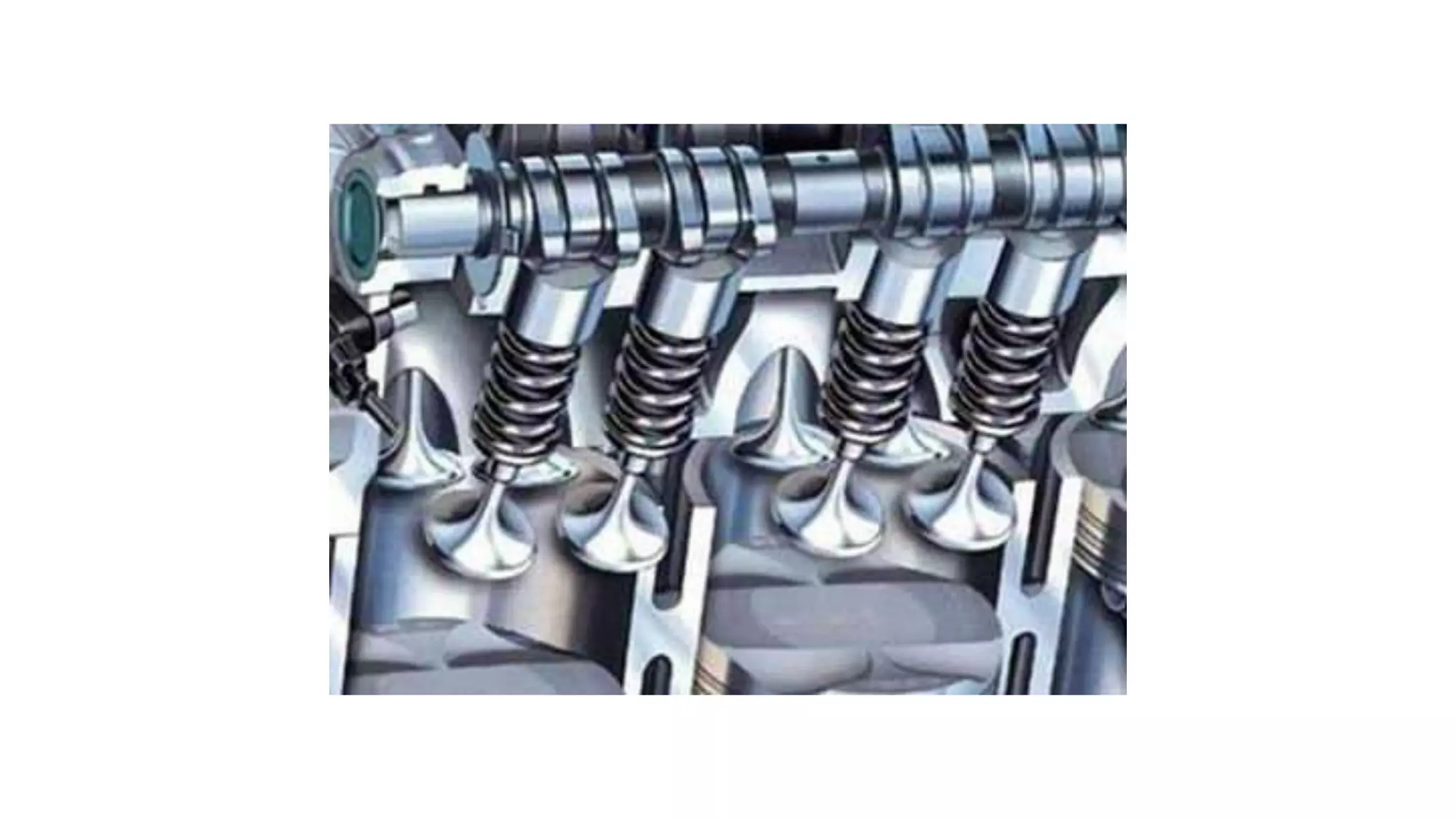
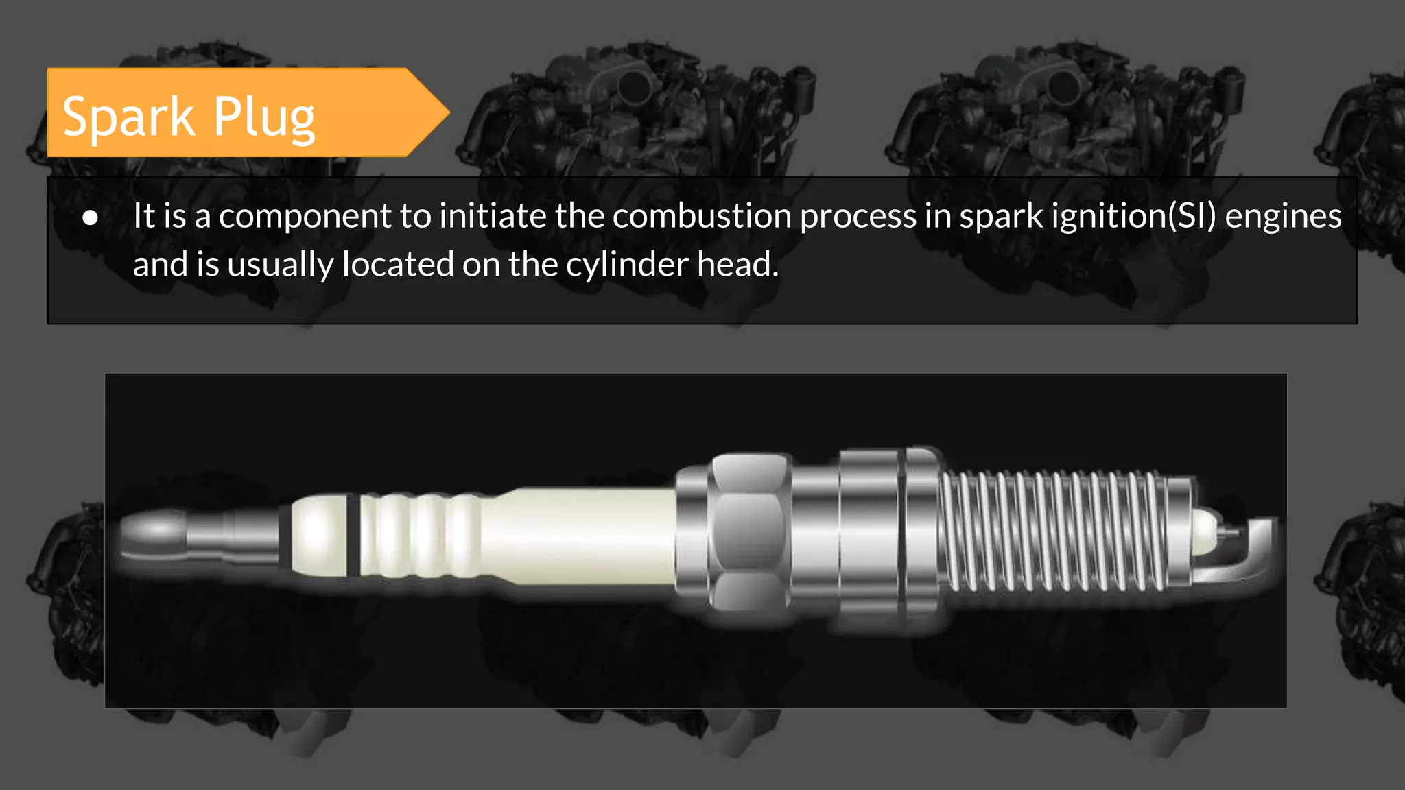
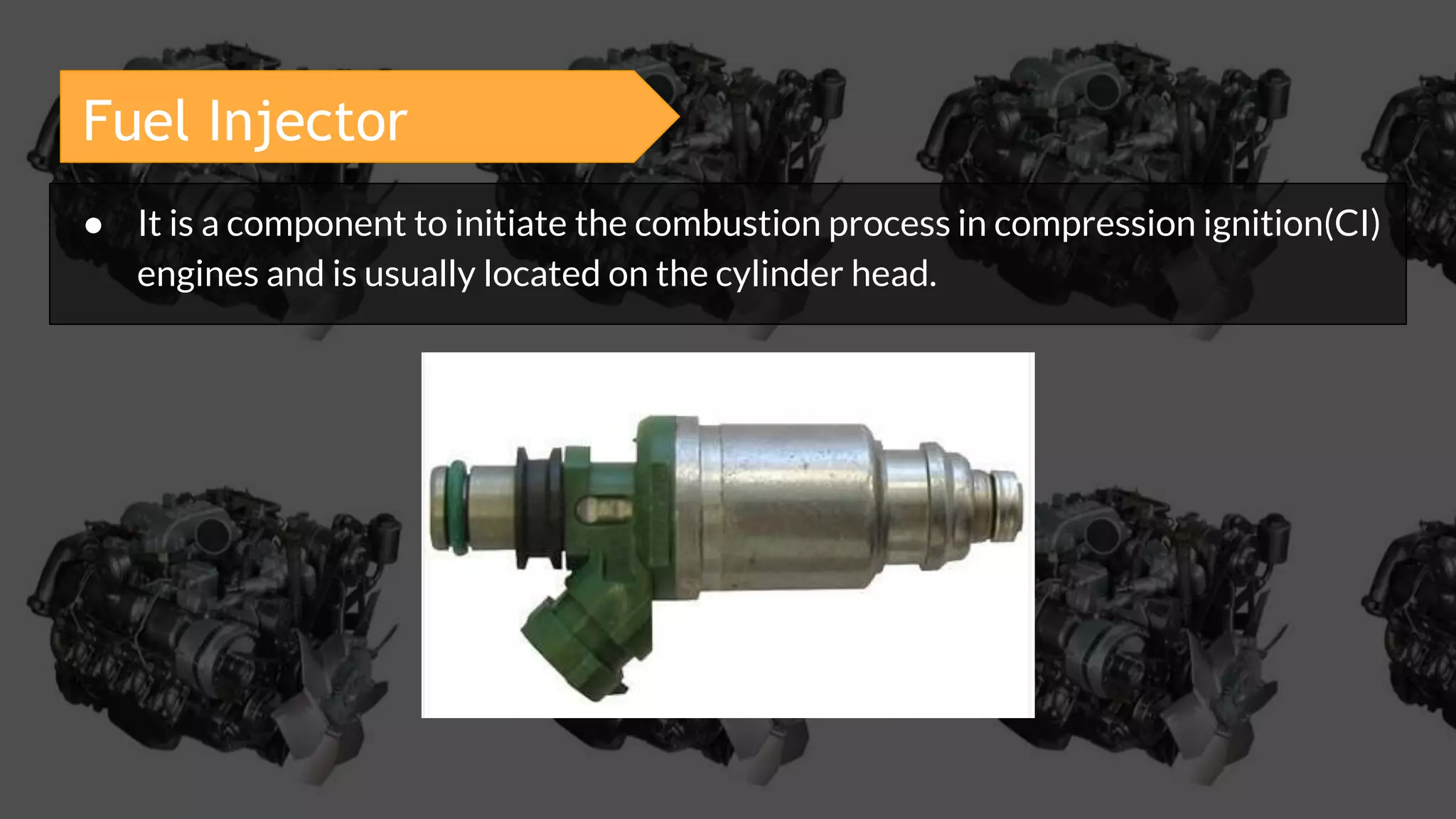
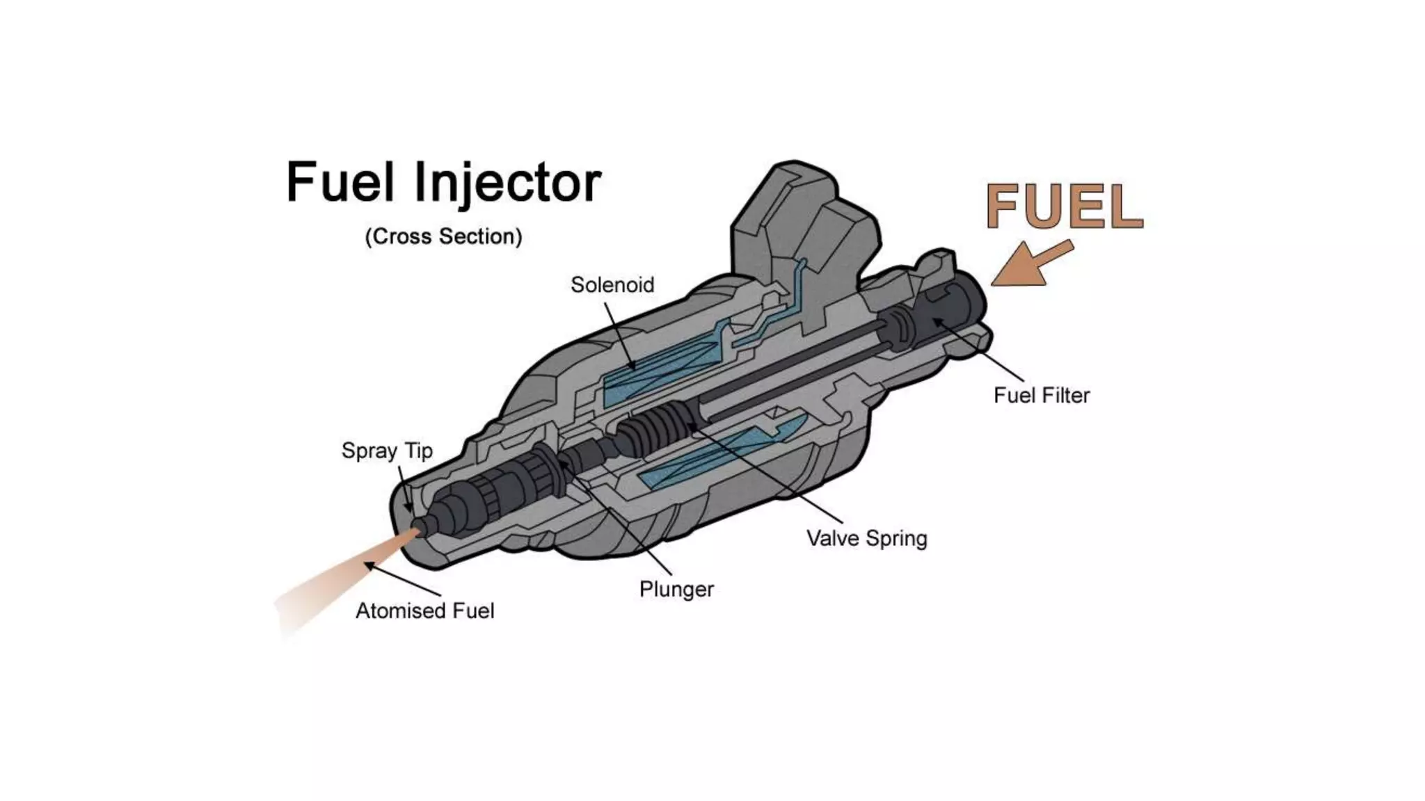
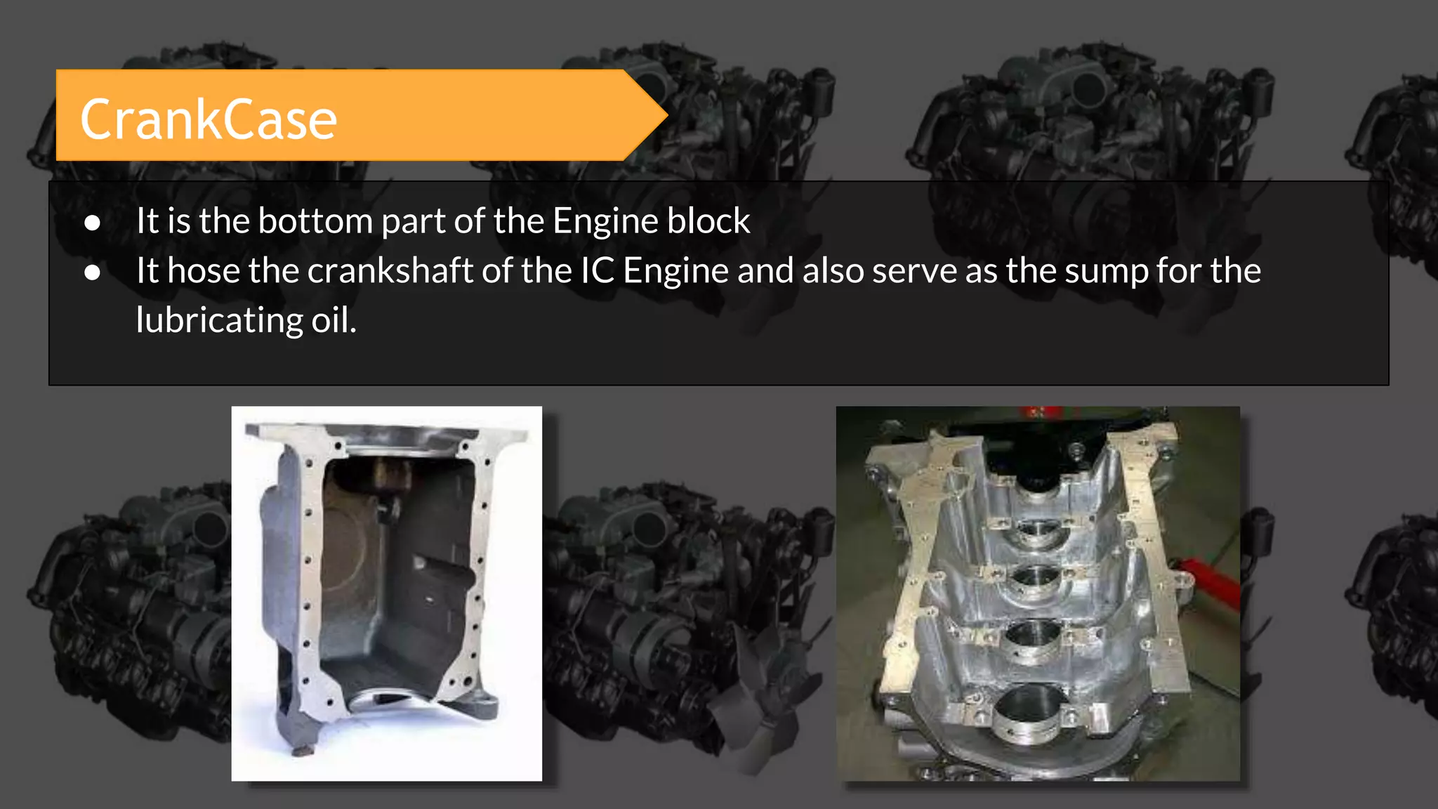
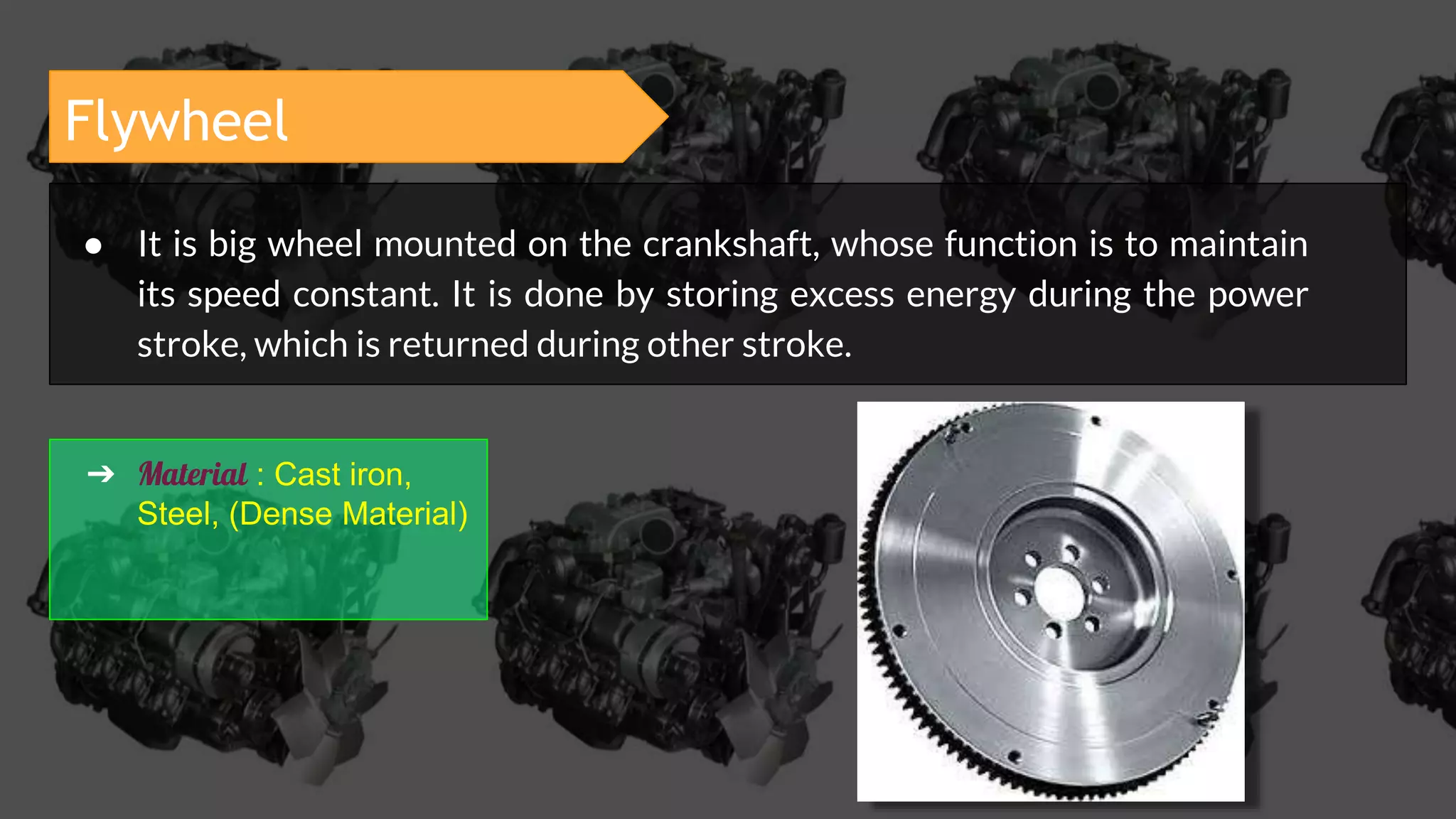
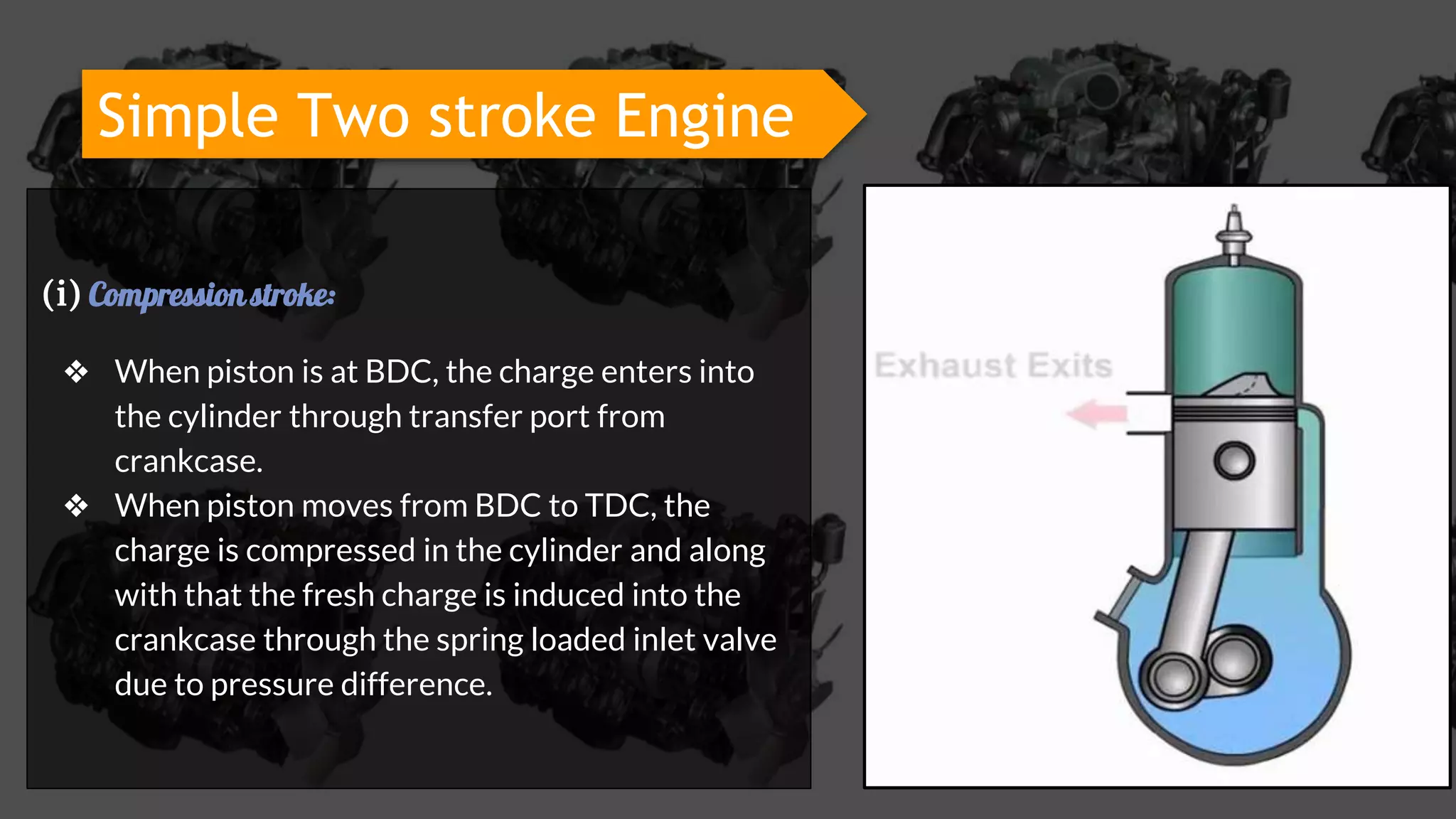
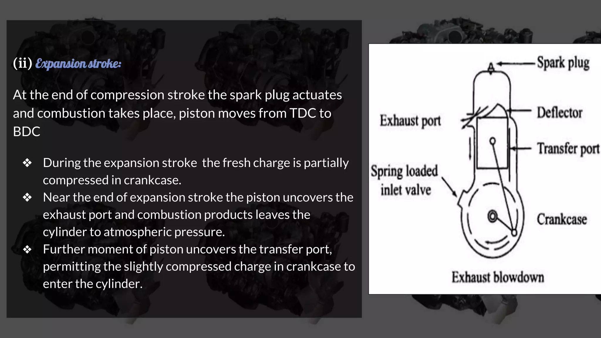
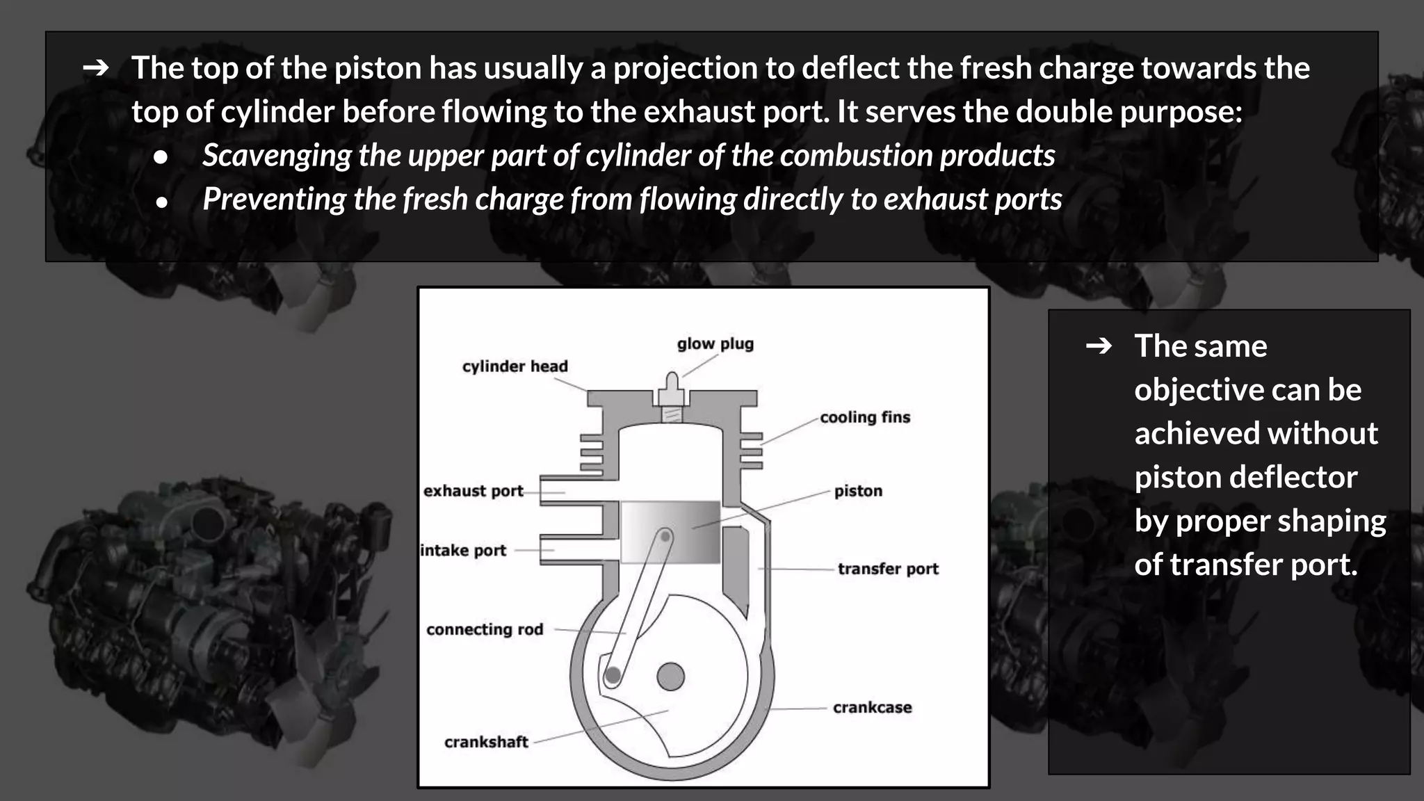
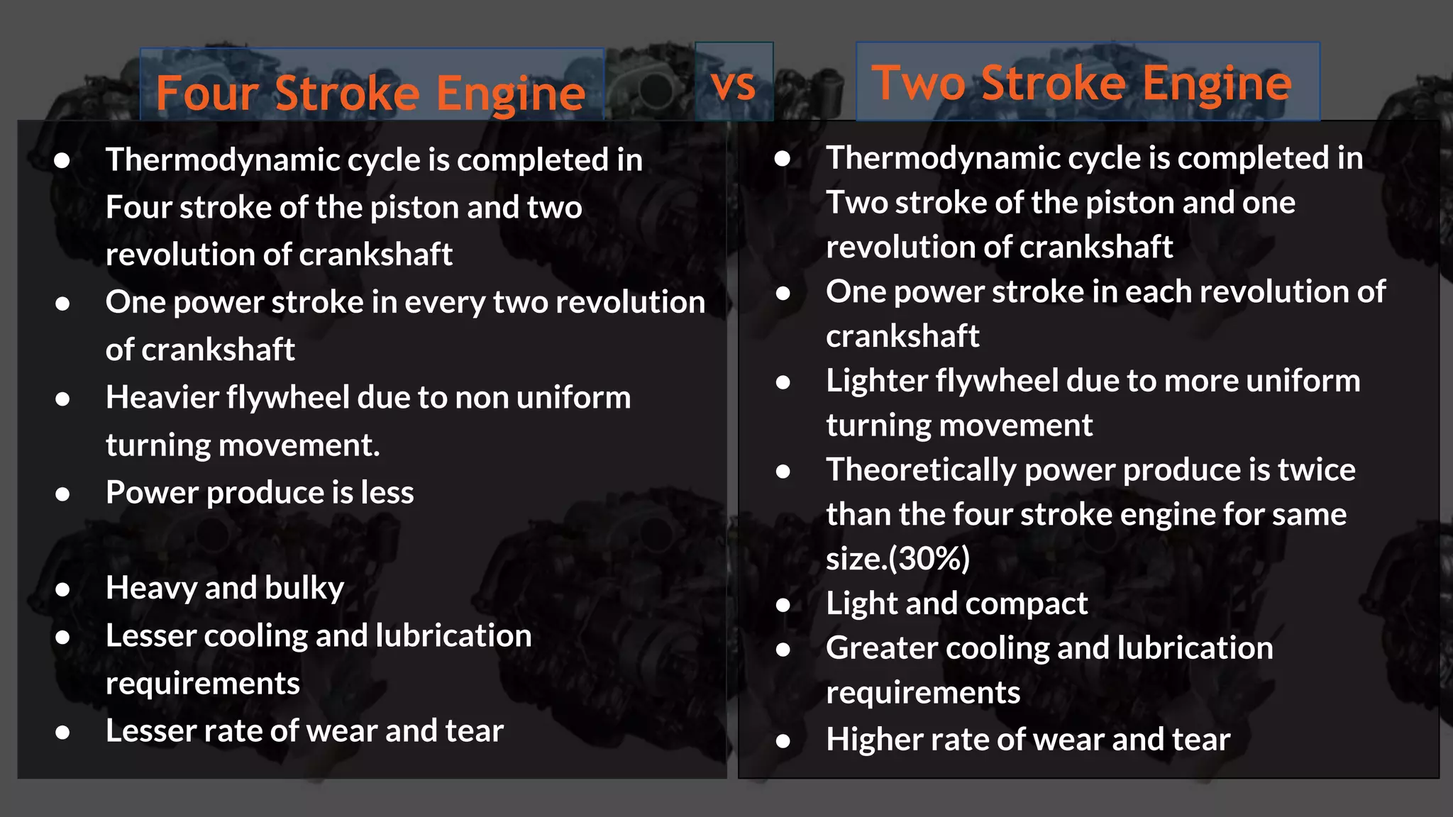
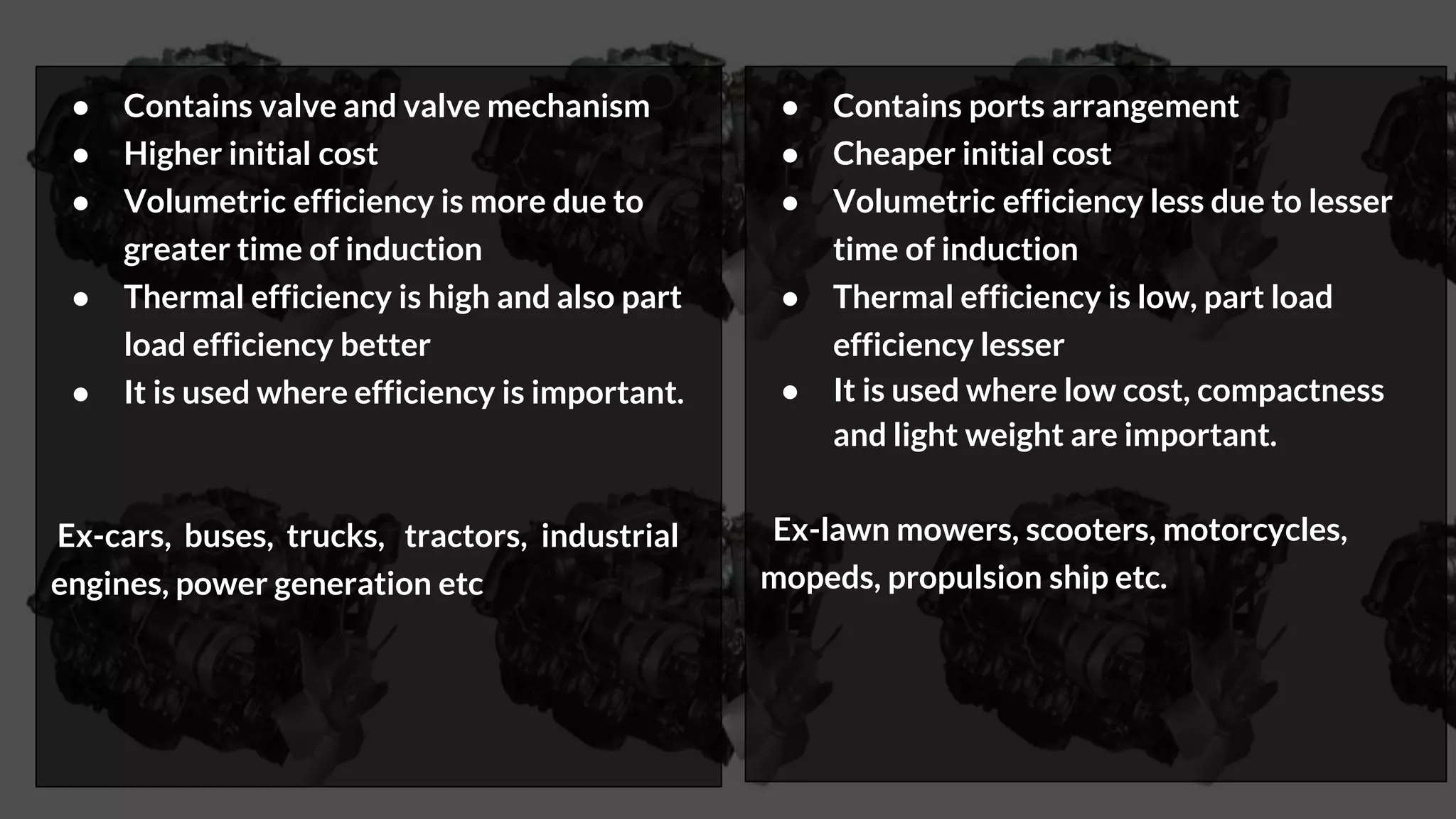
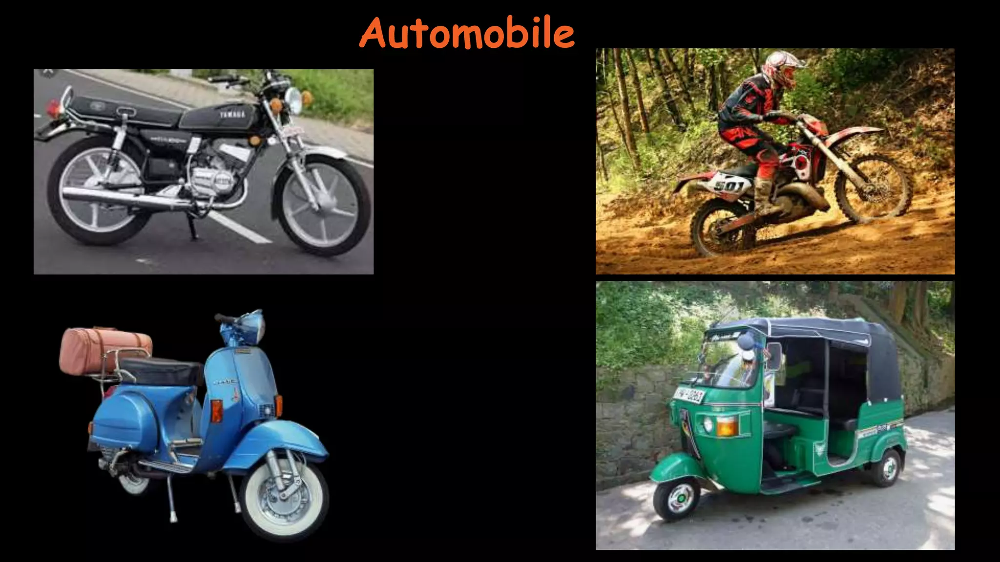
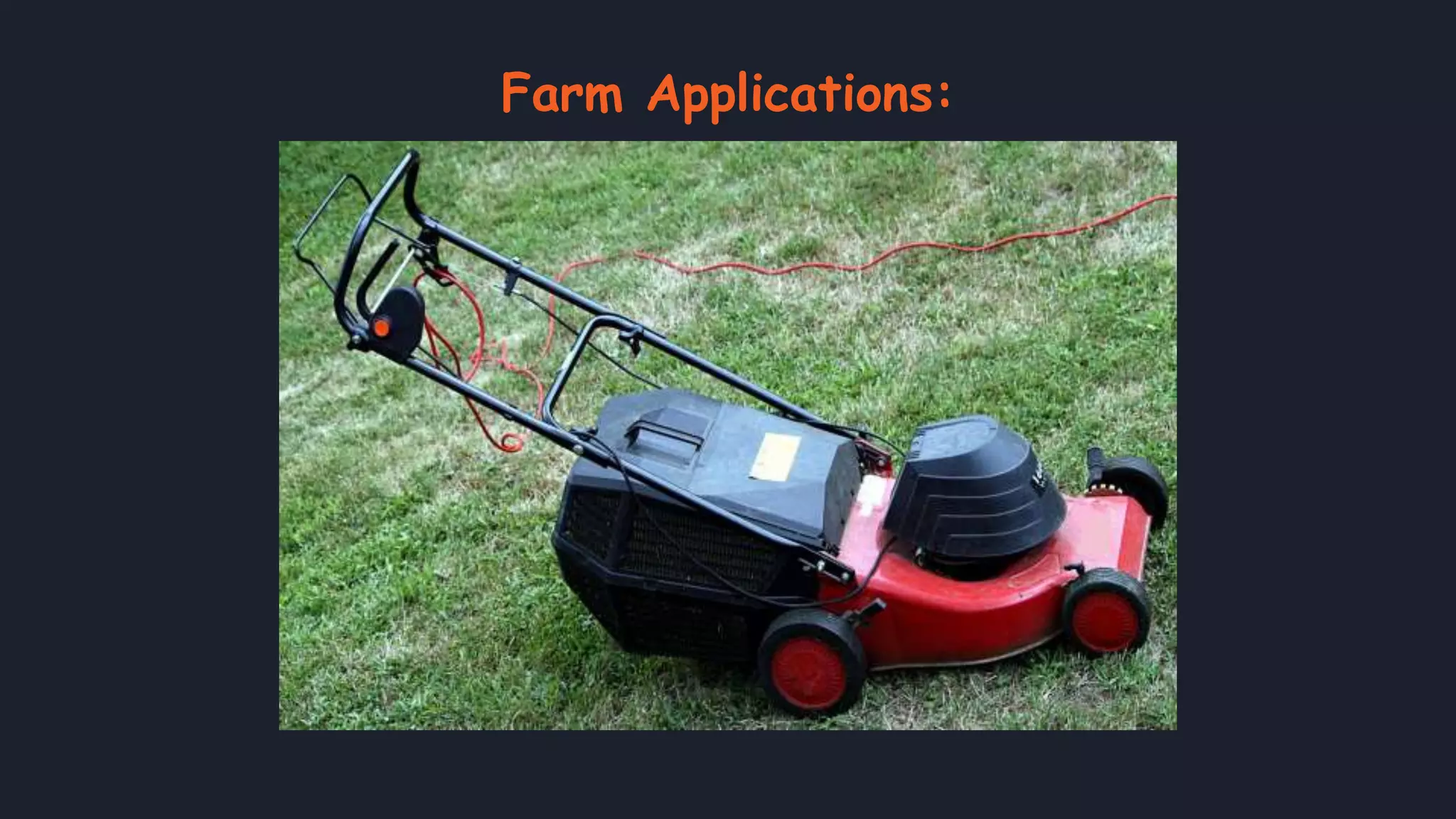
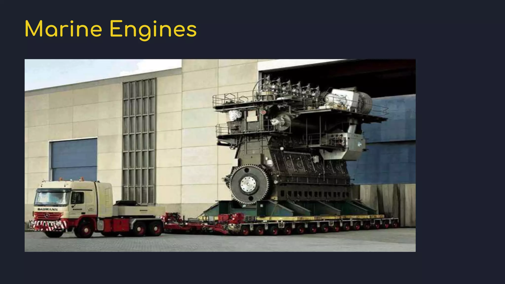
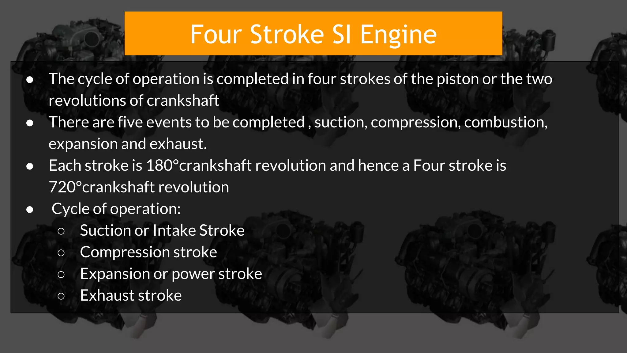
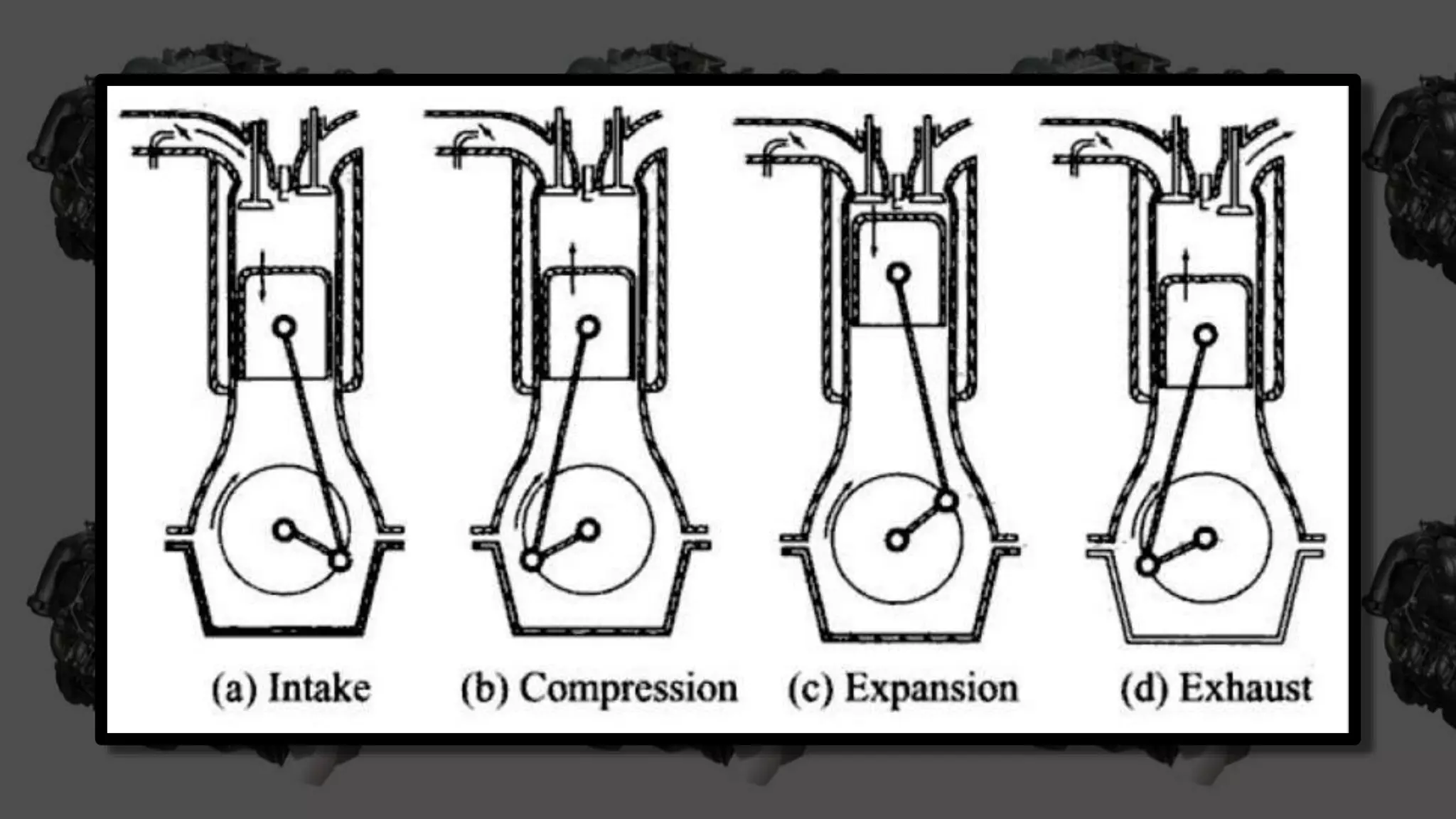
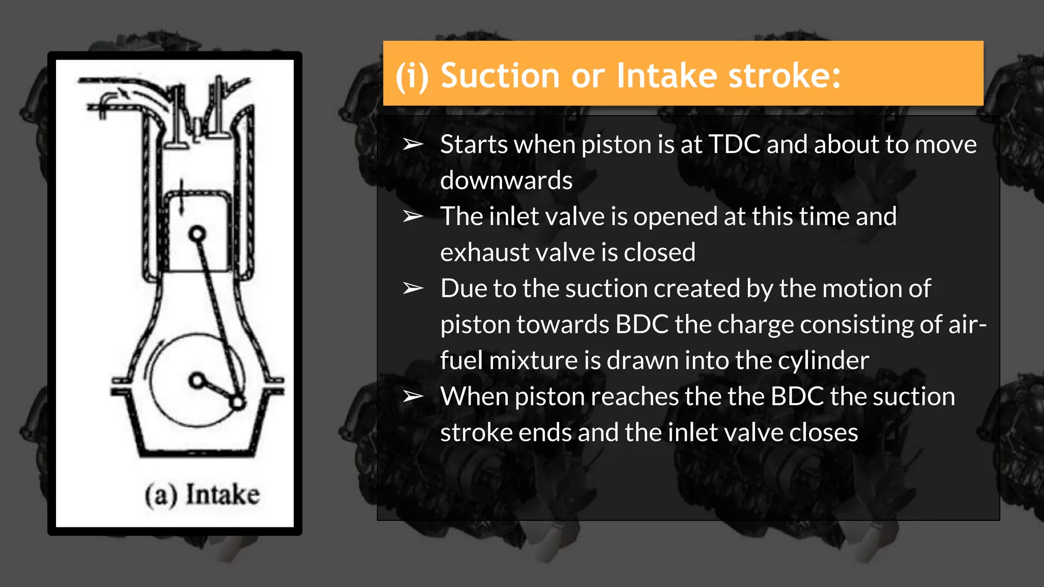
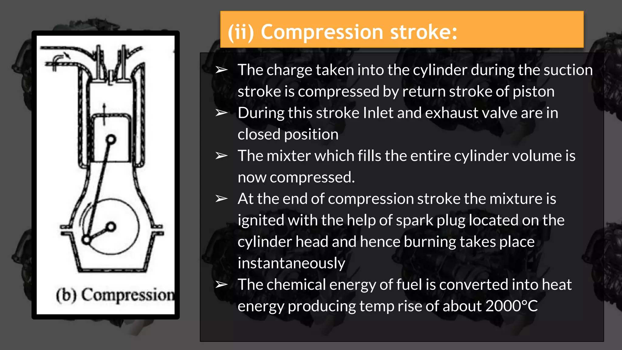
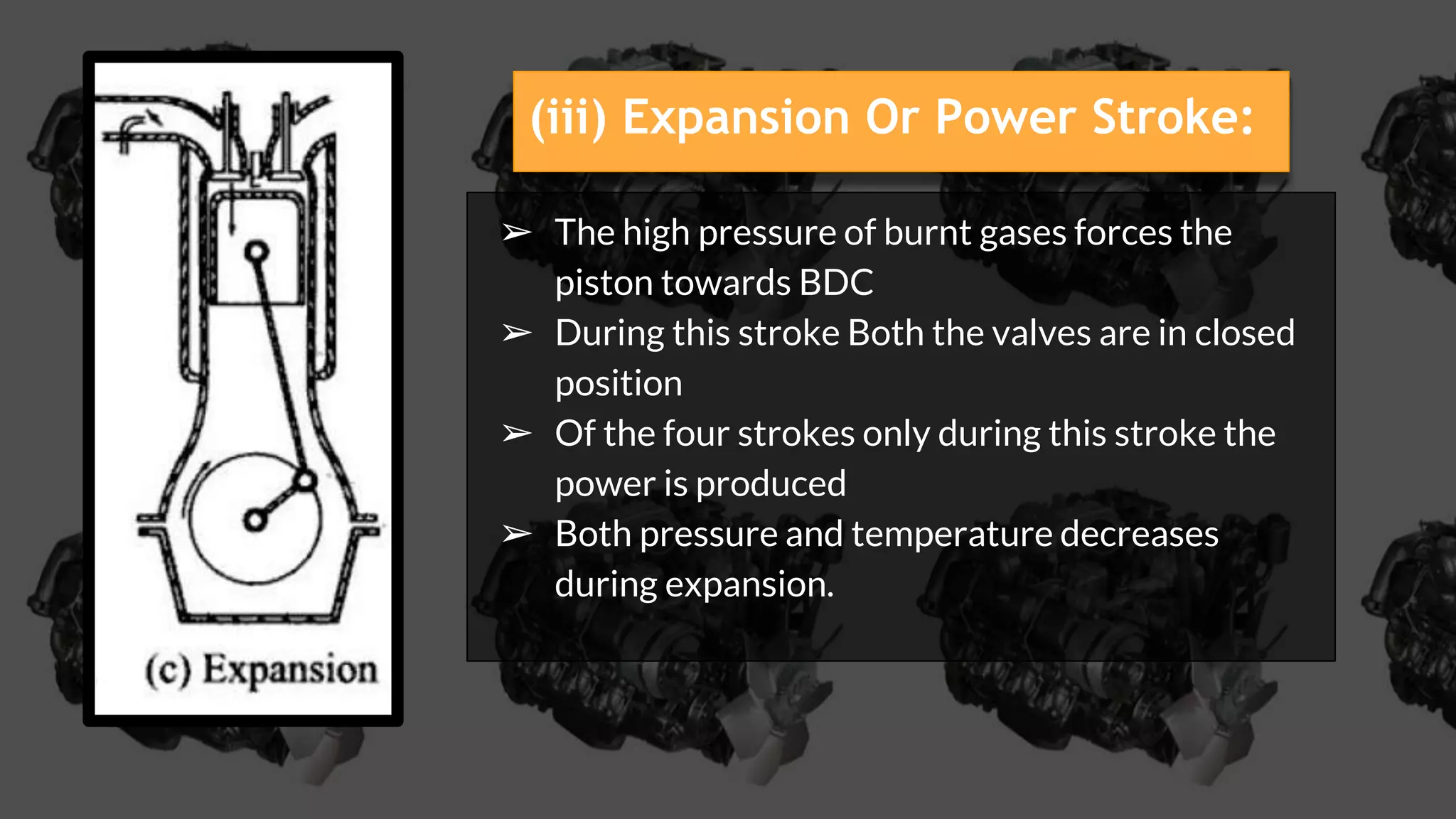
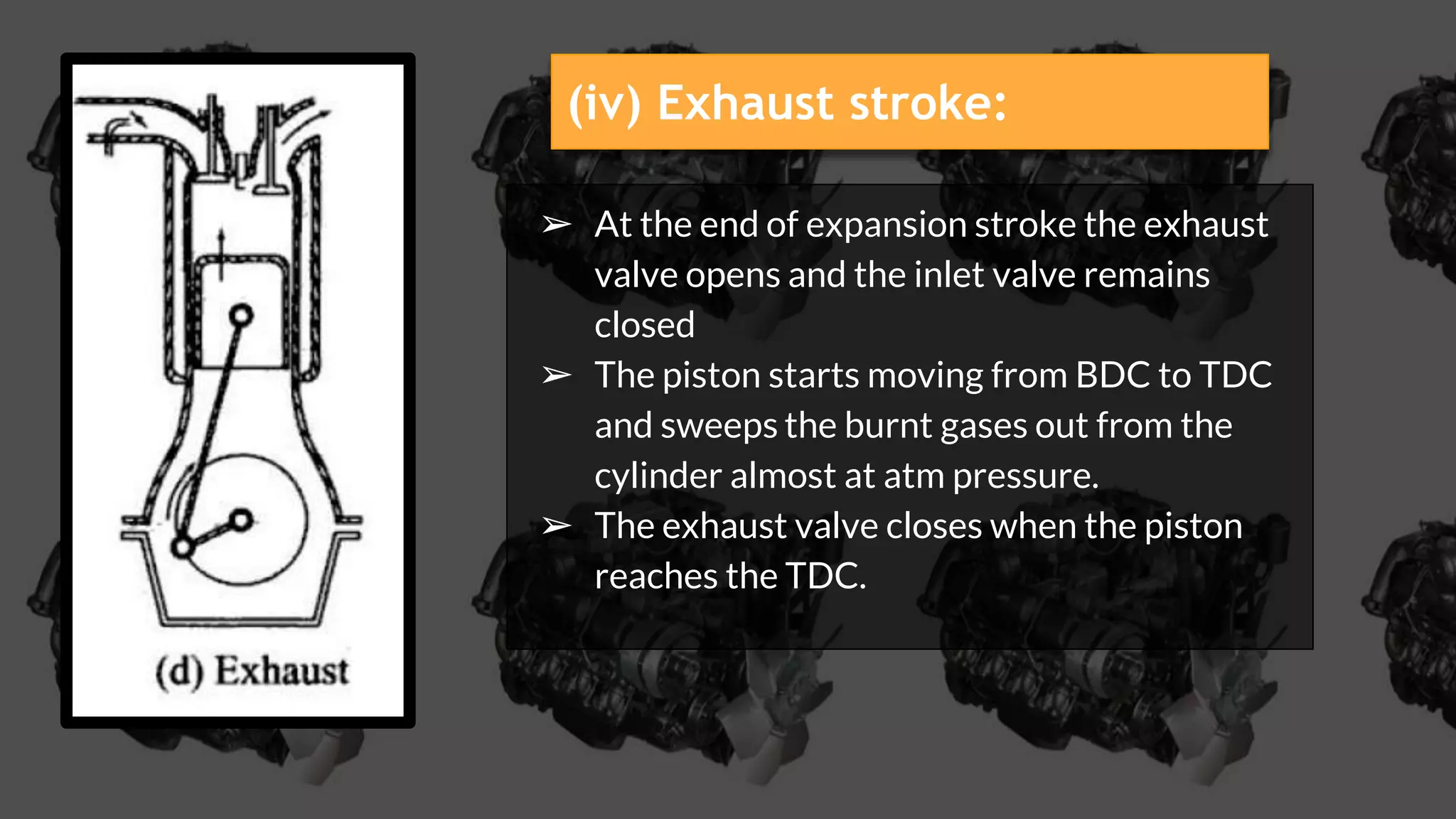
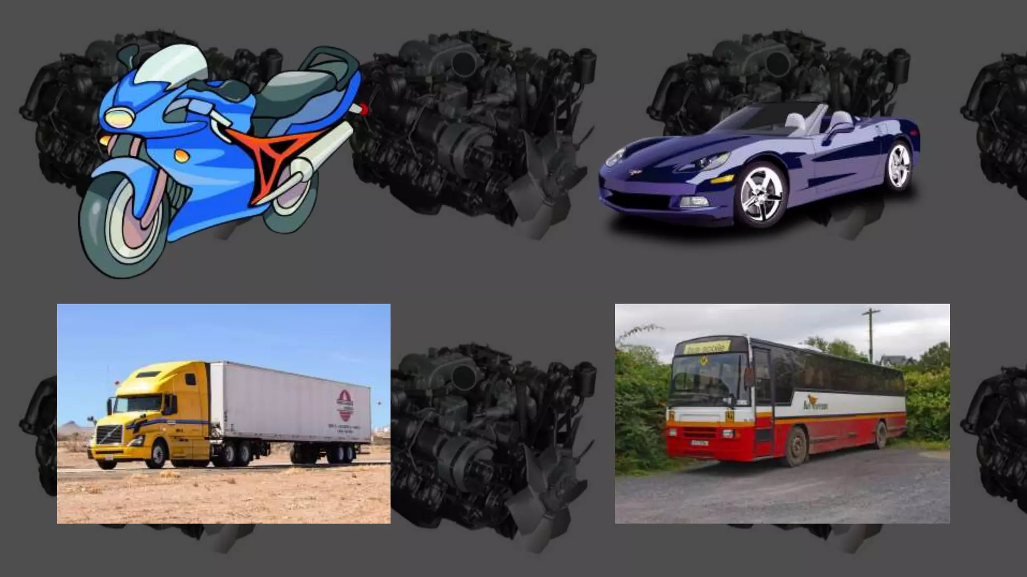
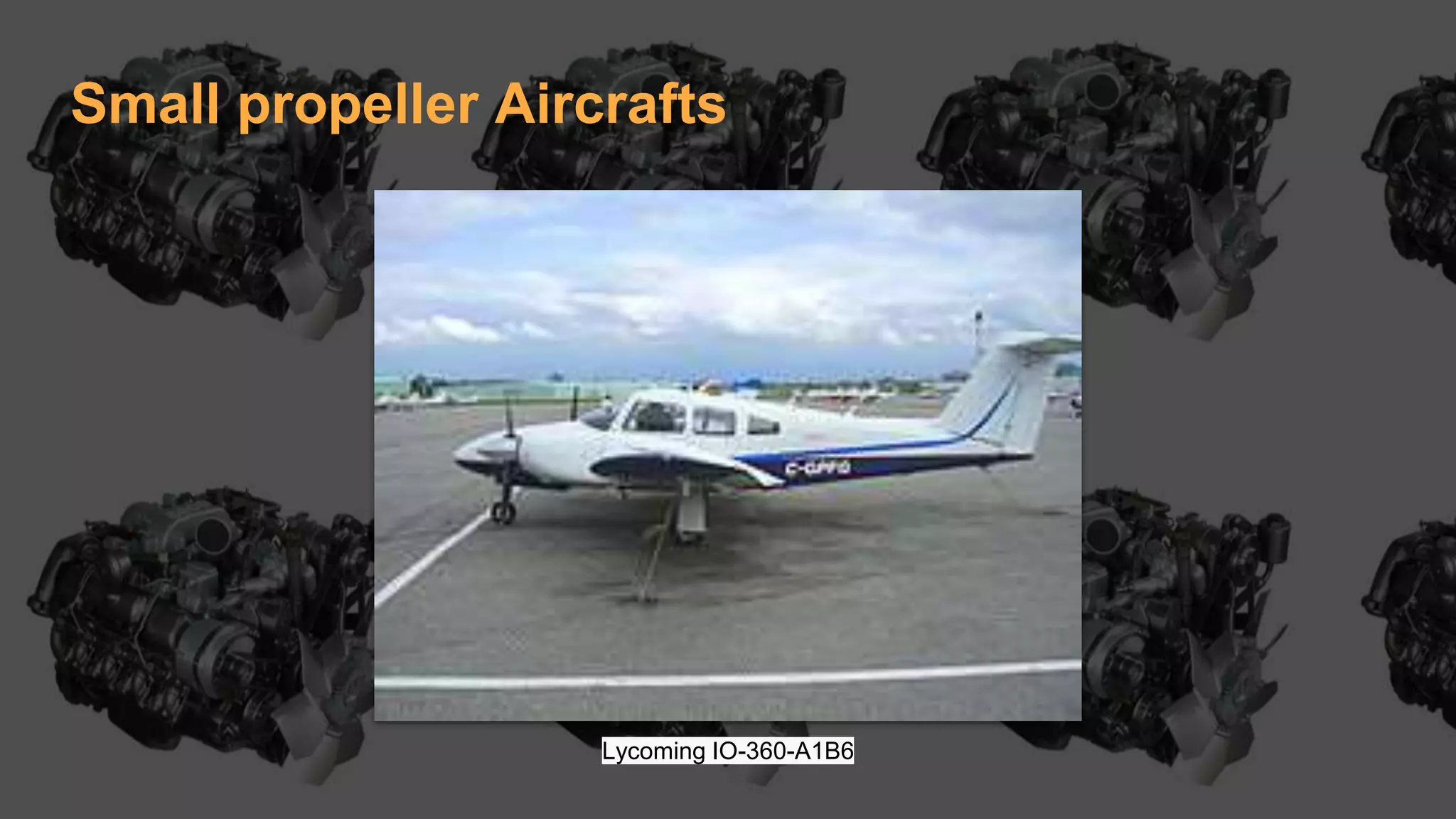
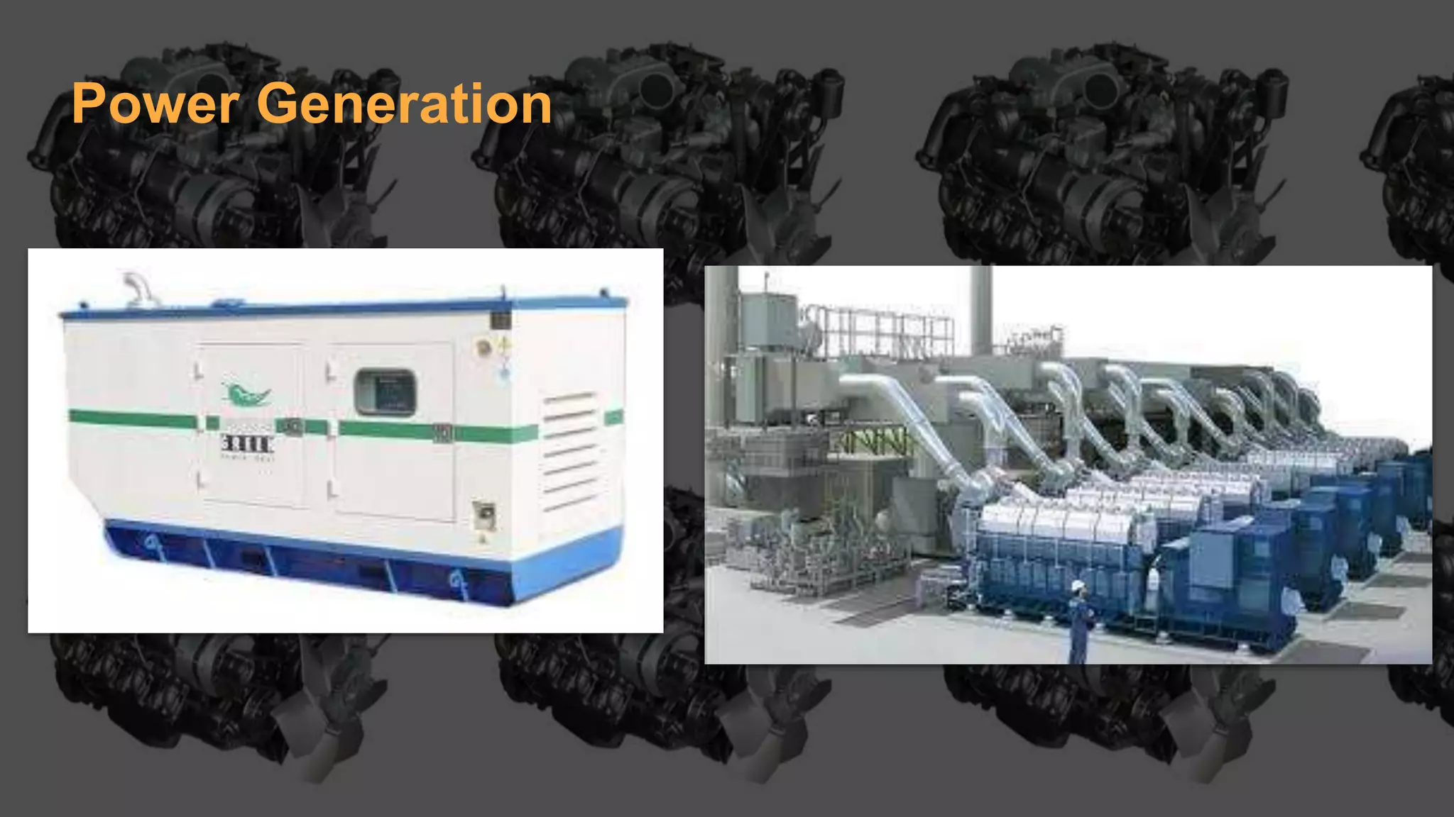
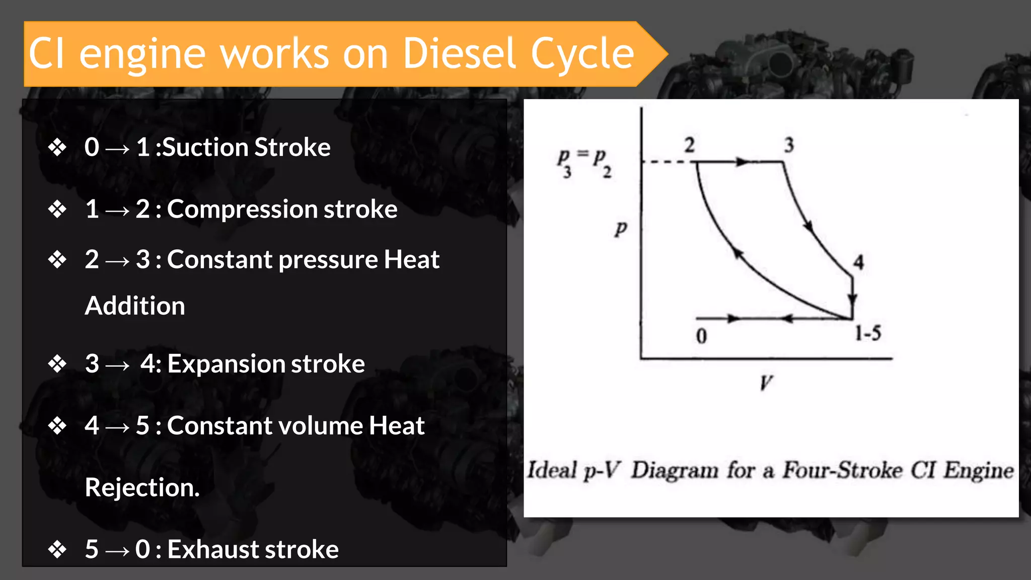
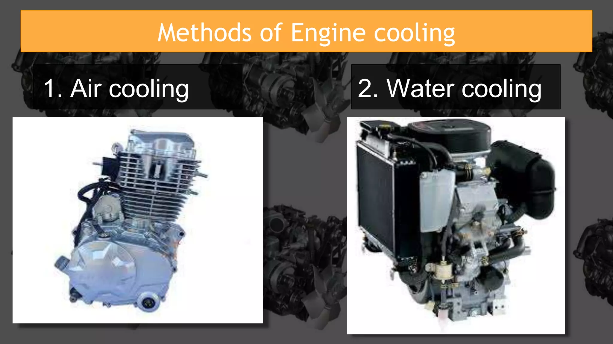
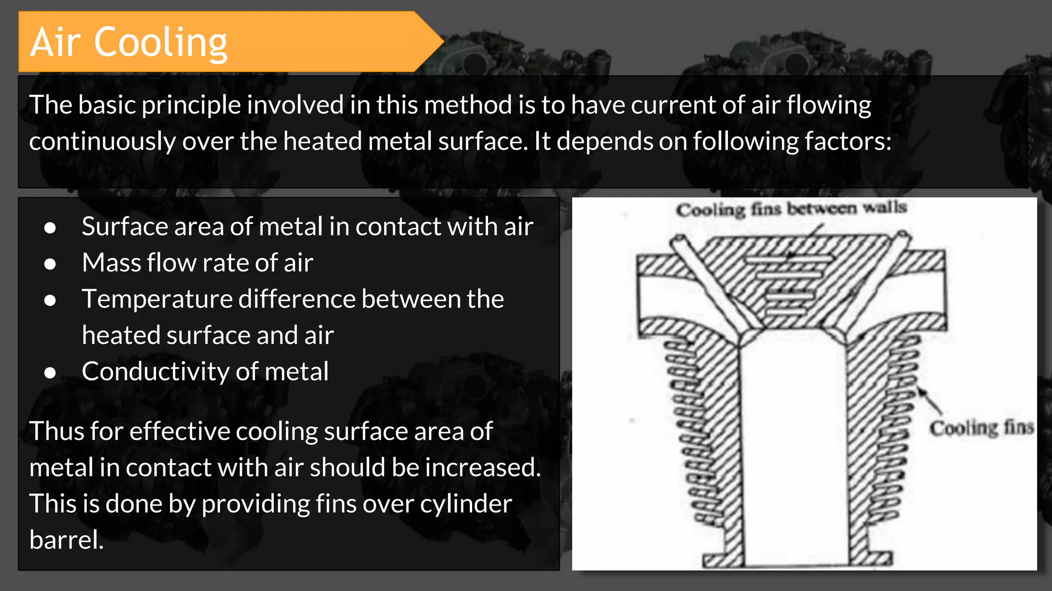
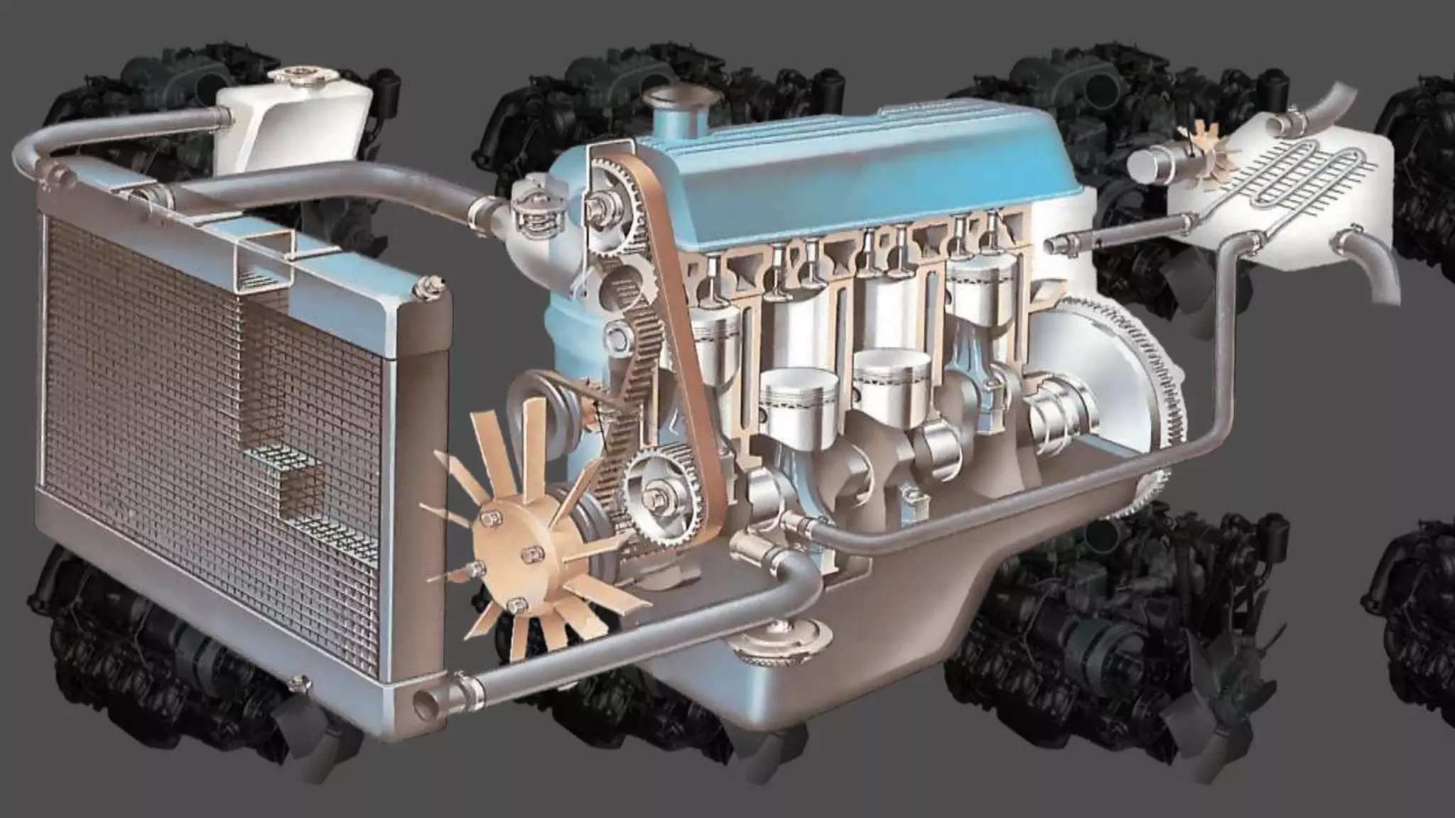
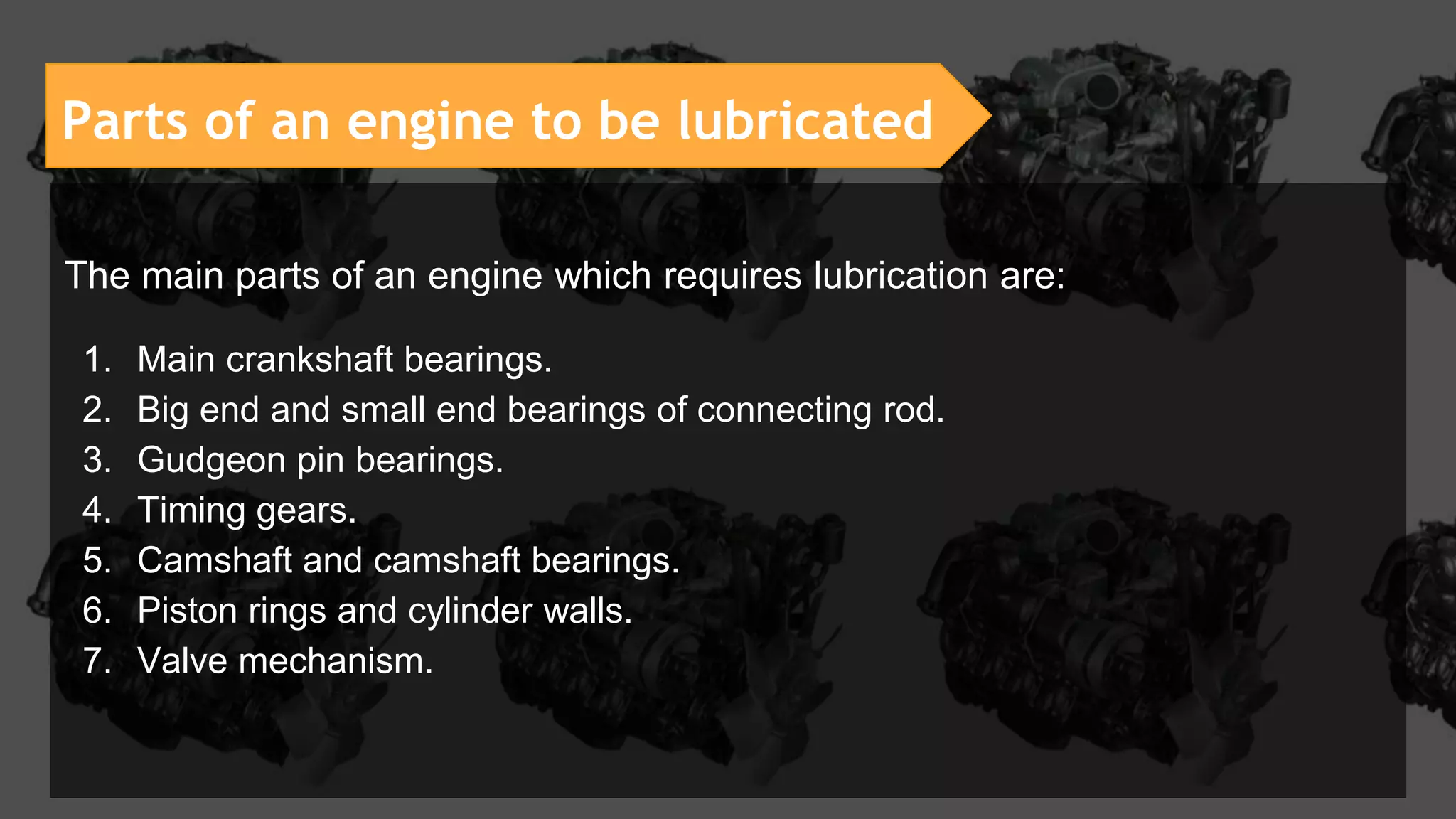
SlideShare a Scribd company logo
Complete guide to
IC Engines
1. Introduction to IC Engines
Heat Engine
A heat engine is a device which transforms the Chemical Energy
of a FUEL into Thermal Energy and uses this energy to produce
Mechanical Work.
● External combustion engine
● Internal combustion engine
It is classified into two types:
External combustion engine :
External combustion engine are those in which the combustion
takes place outside the engine, the products of combustion of air and
fuel transfer heat to a second fluid which is the working fluid of the
cycle.
Limitations of EC Engine:
● A steam engine is huge and heavy. Due to its big Boiler and Furnace.
● Steam Engine does not Start at once.
● It operates on low efficiency. (20%)
● These steam engines are unsafe to use, its boiler can burst due to excessive
steam pressure!
Due to these limitations the EC Engines are replace by IC Engines.
Internal combustion engine :
In this engine the combustion of air fuel mixture takes place inside
the cylinder and used as direct motive force.
● These engines are compact in size.
● IC engine don’t require boiler.
● Higher efficiency about 35-40%.
● Very noisy operated Engines.
Features of IC Engine :
2. Components of IC Engines
● Cylinder block
● Cylinder Head
● Piston
● Cylinder
● Piston Rings
● Gudgeon Pin
● Connecting Rod
● Crankshaft
● Cam Shaft
● Cams
● Inlet & Exhaust valve
● Fuel Injector
● Spark Plug
● Crankcase
● Flywheel
Components of IC Engine
The cylinder block is the main supporting structure for the various components. The
cylinder of multi cylinder engine are cast in single unit called as Cylinder Block
➔ Material : Cast Iron, Aluminum alloy
◆ CI for diesel engines, that
produce stronger explosion.
◆ Al for gasoline engine that
produces soft explosion.
Cylinder Block
Cylinder Head
The top end of the cylinder is covered by cylinder head over which inlet and
exhaust valve, spark plug or injectors are mounted
Piston
● It is cylindrical component fitted into the cylinder forming the moving boundary
of combustion system.
● Transmit the force exerted by the burning of charge to the connecting rod
● It fits perfectly into the cylinder providing a gas-tight space with the piston ring
and lubricant.
➔ Material : aluminium alloy
◆ Light Weight
◆ Thermal Conductivity
◆ Good tensile strength
Cylinder
● It is the main part of the engine in which the piston reciprocate to and fro.
● It also acts in transferring the heat from:
○ combustion chamber to water jacket in liquid cooled engine.
○ Combustion chamber to fins in air cooled engine.
➔ Material : Cast Iron
◆ Good wear Resistance
◆ Good Damping behaviour
◆ High Thermal conductivity
◆ inexpensive
Piston Rings
● Piston rings, fitted into the slots around the piston, provides tight seal between
the piston and cylinder wall thus preventing the leakage of combustion gases.
● There are two types of rings:
○ Compression ring is upper ring of the piston which provides air tight seal to prevent
leakage of the burnt gases into the lower portion.
○ Oil ring is lower ring which provides effective seal to prevent leakage of the oil
into the engine cylinder.
➔ Material : Cast Iron, steel
alloys(coated or heat treated)
◆ High thermal conductivity
◆ Wear resistance
Connecting Rod
● It converts reciprocating motion of the piston into circular motion of the
crankshaft, in the working stroke.
● The smaller end of the connecting rod is connected with the piston by
gudgeon pin and bigger end of the connecting rod is connected with the
crank with crank pin.
➔ Material : Steel alloys(drop
forged), Titanium, Aluminum
◆ Lightweight, flexible (Al)
◆ High performance(Ti)
Gudgeon Pin
It forms the link between the small end of connecting rod and piston
Crankshaft
● It converts the reciprocating motion of the piston into the useful rotary motion
of output shaft with the help of connecting rod.
● In the crankshaft of single cylinder engine there are a pair of crank arms and a
balance weights. The balance weights are provided for static and dynamic
balancing of the rotatory system.
● The crankshaft is enclose in the crankcase
➔ Material: Medium carbon
steel alloy(0.25-0.45%C) -
Foging
◆ High fatigue strength
◆ Hardness
Cam Shaft
● The cam shaft and its associate parts control the opening and closing of two
valves. The associate parts are pushrod, rocker arms,valve spring and tappets.
● The shaft also provide the drive to the ignition system.
● The camshaft is driven by the crankshaft through timing chain or timing gears.
➔ Material : chilled cast iron(1% Cr),
Billet Steel.
◆ high volume production,
have good wear resistance.
◆ high quality camshaft or low
volume production
Cams
These are made as integral parts of the camshaft and are designed in such a way to
open the valves at the correct timings and to keep them open for necessary duration
Cams
Inlet and exhaust valves
● Valves are commonly mushroom shape poppet type
● They are provided on the cylinder head for regulating the charge coming into
the cylinder(inlet valve) and for discharging the products of combustion
(exhaust valve) from the cylinder.
➔ Material: Stainless steel,
Titanium, Inconel,
◆ high
temperature,oxidation
,corrosion resistant
Spark Plug
● It is a component to initiate the combustion process in spark ignition(SI) engines
and is usually located on the cylinder head.
Fuel Injector
● It is a component to initiate the combustion process in compression ignition(CI)
engines and is usually located on the cylinder head.
CrankCase
● It is the bottom part of the Engine block
● It hose the crankshaft of the IC Engine and also serve as the sump for the
lubricating oil.
Flywheel
● It is big wheel mounted on the crankshaft, whose function is to maintain
its speed constant. It is done by storing excess energy during the power
stroke, which is returned during other stroke.
➔ Material : Cast iron,
Steel, (Dense Material)
3.Two Stroke Engine
(i) Compression stroke:
❖ When piston is at BDC, the charge enters into
the cylinder through transfer port from
crankcase.
❖ When piston moves from BDC to TDC, the
charge is compressed in the cylinder and along
with that the fresh charge is induced into the
crankcase through the spring loaded inlet valve
due to pressure difference.
Simple Two stroke EngineSimple Two stroke Engine
(ii) Expansion stroke:
At the end of compression stroke the spark plug actuates
and combustion takes place, piston moves from TDC to
BDC
❖ During the expansion stroke the fresh charge is partially
compressed in crankcase.
❖ Near the end of expansion stroke the piston uncovers the
exhaust port and combustion products leaves the
cylinder to atmospheric pressure.
❖ Further moment of piston uncovers the transfer port,
permitting the slightly compressed charge in crankcase to
enter the cylinder.
➔ The top of the piston has usually a projection to deflect the fresh charge towards the
top of cylinder before flowing to the exhaust port. It serves the double purpose:
● Scavenging the upper part of cylinder of the combustion products
● Preventing the fresh charge from flowing directly to exhaust ports
➔ The same
objective can be
achieved without
piston deflector
by proper shaping
of transfer port.
Two stroke Engine
❖ In two stroke engine the cycle is completed in one revolution of crankshaft
❖ The main difference is in the method of filling the fresh charge and removing the burnt gases
from the cylinder
❖ In two stroke the filling process is accomplished by charge compressed in crankcase.
❖ The induction of compressed charge moves out combustion products through exhaust port.
❖ Therefore no piston strokes required for suction and exhaust operation.
❖ Two strokes are sufficient to complete the cycle one for compressing the fresh charge and
other for expansion or power stroke.
Four Stroke Engine
● Thermodynamic cycle is completed in
Four stroke of the piston and two
revolution of crankshaft
● One power stroke in every two revolution
of crankshaft
● Heavier flywheel due to non uniform
turning movement.
● Power produce is less
● Heavy and bulky
● Lesser cooling and lubrication
requirements
● Lesser rate of wear and tear
● Thermodynamic cycle is completed in
Two stroke of the piston and one
revolution of crankshaft
● One power stroke in each revolution of
crankshaft
● Lighter flywheel due to more uniform
turning movement
● Theoretically power produce is twice
than the four stroke engine for same
size.(30%)
● Light and compact
● Greater cooling and lubrication
requirements
● Higher rate of wear and tear
vs Two Stroke Engine
● Contains valve and valve mechanism
● Higher initial cost
● Volumetric efficiency is more due to
greater time of induction
● Thermal efficiency is high and also part
load efficiency better
● It is used where efficiency is important.
Ex-cars, buses, trucks, tractors, industrial
engines, power generation etc
● Contains ports arrangement
● Cheaper initial cost
● Volumetric efficiency less due to lesser
time of induction
● Thermal efficiency is low, part load
efficiency lesser
● It is used where low cost, compactness
and light weight are important.
Ex-lawn mowers, scooters, motorcycles,
mopeds, propulsion ship etc.
Applications of Two Stroke Engine:
Automobile
Farm Applications:
Marine Engines
4. Four Stroke SI Engine
Four Stroke SI Engine
● The cycle of operation is completed in four strokes of the piston or the two
revolutions of crankshaft
● There are five events to be completed , suction, compression, combustion,
expansion and exhaust.
● Each stroke is 180°crankshaft revolution and hence a Four stroke is
720°crankshaft revolution
● Cycle of operation:
○ Suction or Intake Stroke
○ Compression stroke
○ Expansion or power stroke
○ Exhaust stroke
➢ Starts when piston is at TDC and about to move
downwards
➢ The inlet valve is opened at this time and
exhaust valve is closed
➢ Due to the suction created by the motion of
piston towards BDC the charge consisting of air-
fuel mixture is drawn into the cylinder
➢ When piston reaches the the BDC the suction
stroke ends and the inlet valve closes
(i) Suction or Intake stroke:
➢ The charge taken into the cylinder during the suction
stroke is compressed by return stroke of piston
➢ During this stroke Inlet and exhaust valve are in
closed position
➢ The mixter which fills the entire cylinder volume is
now compressed.
➢ At the end of compression stroke the mixture is
ignited with the help of spark plug located on the
cylinder head and hence burning takes place
instantaneously
➢ The chemical energy of fuel is converted into heat
energy producing temp rise of about 2000°C
(ii) Compression stroke:
➢ The high pressure of burnt gases forces the
piston towards BDC
➢ During this stroke Both the valves are in closed
position
➢ Of the four strokes only during this stroke the
power is produced
➢ Both pressure and temperature decreases
during expansion.
(iii) Expansion Or Power Stroke:
➢ At the end of expansion stroke the exhaust
valve opens and the inlet valve remains
closed
➢ The piston starts moving from BDC to TDC
and sweeps the burnt gases out from the
cylinder almost at atm pressure.
➢ The exhaust valve closes when the piston
reaches the TDC.
(iv) Exhaust stroke:
Four stroke engine completes the above four operation in two engine
revolutions
➔ One revolution of crankshaft occurs during suction & compression
stroke
➔ And Second revolution during the power & exhaust stroke
Thus in one complete cycle there is only one power stroke while the
crankshaft turns by two revolution
Four Stroke CI Engine
The four stroke CI Engine is similar to four stroke SI engine but it operates
at a much higher compression ratio.
Compression Ratio: In SI engine is “6 to 10”
In CI engine is “16 to 20”
Due to the high compression ratio temperature at the end of compression
stroke is sufficiently high to self ignite the fuel.
(i)Suction stroke:
Air alone is induced during the suction stroke
During this stroke inlet valve is opened and
exhaust valve is closed
(ii)Compression stroke:
Air induced during the suction stroke is
compressed into clearance volume
Both valves remains closed during this stroke
(iii)Expansion stroke:
Fuel injection starts nearly at the end of the
compression stroke
After injection of the fuel is completed the product
of combustion expand
Both valve remains closed during the expansion
stroke
(iv)Exhaust stroke:
Piston travelling from BDC to TDC pushes out the
product of combustion
The exhaust valve is opened and inlet valve is
closed during this stroke
Applications of 4 stroke engine:
Locomotives:
Small propeller Aircrafts
Lycoming IO-360-A1B6
Small outboard motor
Power Generation
5.Six stroke Engine
Six stroke Engine
● In six stroke engine the thermodynamic cycle is completed in 3
revolution of crankshaft.
● The main difference is the addition of two extra strokes i.e.,
2nd power stroke and exhaust stroke.
● The engine captures the exhausted heat from the four stroke
cycle and uses it to get an additional power of the piston in the
same cylinder.
Velozeta six-stroke engine
In a Velozeta engine, fresh air is injected into the cylinder during the exhaust
stroke, which expands by heat and therefore forces the piston down for an
additional stroke. The two additional strokes using air injection provide for
better gas scavenging. The engine seems to show 40% reduction in fuel
consumption and dramatic reduction in air pollution.Its Power-to-weight ratio is
slightly less than that of a four-stroke gasoline engine. The engine was
developed in 2005 by a team of mechanical engineering students from kerala.
Crower six-stroke engine
This six-stroke engine prototyped in the United States by Bruce Crower, water
is injected into the cylinder after the exhaust stroke and is instantly turned to
steam, which expands and forces the piston down for an additional power
stroke.Crower estimated that his design would reduce fuel consumption by 40%
by generating the same power output at a lower rotational speed.
Working:
● The first four stroke are same as that of four stroke engine
● Suction stroke : charge is sucked into the cylinder, piston moves from TDC to
BDC.Inlet valve remains open during this stroke
● Compression stroke : air fuel mixture or charge is compressed in the cylinder,
piston moves from BDC to TDC. Both the valves remains closed. At the end of
compression stroke the air fuel mixture is ignited with the help of spark plug
and burning of gases takes place.
● Expansion or powerstroke : The high pressure gases forces the piston down to
BDC. during this stroke both the valves remains closed. This is the first power
stroke produced in cycle with the help of fuel.
● Exhaust stroke : at the end of expansion stroke the exhaust valve opens and inlet
valve remains closed. The piston will exhale the burnt gases out of the cylinder.
● 2nd power stroke :
○ the fresh air from air filter enters the cylinder through the secondary air
induction line.(velozeta)
○ The water is injected in the super heated cylinder. Through hot gases the water
changes its phase into steam as the temperature of hot gases is high. This steam
will act as a working fluid and forces the piston downwards. (crower)
● 2nd Exhaust stroke : during the sixth stroke the exhaust valve remains open. The
piston discharges the gases out of the cylinder.
Working:
Velozeta six-stroke engine e e
Crower six-stroke engine e
Features of six stroke engine:
● The efforts in cooling the engine is considerably reduced and makes the engine lighter.
● Six stroke engine seems to show 40% reduction in fuel consumption.
● This engine shows around 60% reduction in carbon monoxide pollution when
compared to four stroke gasoline engine.
6. Spark Ignition Engine
or
Gasoline(Petrol) Engine
❖ 0 → 1 :Suction Stroke
❖ 1 → 2 : Compression stroke
❖ 2 → 3 : Constant volume Heat Addition
❖ 3 → 4: Expansion stroke
❖ 4 → 5 : Const vol Heat Rejection.
❖ 5 → 0 : Exhaust stroke
SI Engine Works on Otto Cycle
● Basic Cycle:
○ Works on Otto cycle or constant volume heat addition cycle.
● Fuel:
○ Gasoline, a highly volatile fuel. Self ignition temperature is high i.e.,280°C
whereas for diesel it is 210°C.
● Introduction of fuel:
○ A gaseous mixture of air-fuel is introduced during the suction stroke.
○ Carburetor and ignition system are necessary
● Load Control:
○ Throttle controls the quantity of fuel air mixture introduced.
Features of SI Engine
● Ignition:
○ Requires Ignition system with spark plug in the combustion chamber. Primary
voltage is provided by a battery.
● Compression Ratio:
○ 6-10 upper limit is fixed by antiknock quality of fuel.
● Speed:
○ Due to light weight and also due to homogeneous combustion, they are high
speed engines.
● Thermal Efficiency:
○ Because of low compression ratio the maximum value of thermal efficiency
that can be obtained is lower
● Weight:
○ Lighter due to lower peak pressure.
7. Compression Ignition Engine
or
Diesel Engine
CI engine works on Diesel Cycle
❖ 0 → 1 :Suction Stroke
❖ 1 → 2 : Compression stroke
❖ 2 → 3 : Constant pressure Heat
Addition
❖ 3 → 4: Expansion stroke
❖ 4 → 5 : Constant volume Heat
Rejection.
❖ 5 → 0 : Exhaust stroke
➔ Basic Cycle:
◆ Works on diesel cycle or constant pressure heat addition cycle.
➔ Fuel:
◆ Diesel oil a non-volatile fuel. Self ignition temperature is comparatively low.
➔ Introduction of fuel:
◆ Fuel is injected directly into the combustion chamber at the high pressure at
the end
of compression stroke.
◆ A fuel pump and injector are necessary.
Features of CI Engine
➔ Load Control:
◆ The quality of fuel is regulated. Air quantity is not controlled.
➔ Ignition:
◆ Self ignition occurs due to high temperature of air because of high
compression.
◆ Ignition system and spark plug are not necessary.
➔ Compression Ratio:
◆ 16-20 upper limit is limited by weight increase of engine
➔ Speed:
◆ Due to heavy weight and also due to heterogeneous combustion, they are
low speed engines.
➔ Thermal Efficiency:
◆ Because of higher compression ratio the maximum value of thermal efficiency
that can be obtained is higher.
➔ Weight:
◆ Heavier due to higher peak pressure.
8. Engine Cooling System
➔ All heat produced by combustion of fuel is not converted into useful work at
crankshaft. A typical distribution for the fuel energy is given below:
◆ Useful work at crankshaft = 25%
◆ Loss to the cylinder wall = 30%
◆ Loss to exhaust gases = 35%
◆ Loss in friction = 10%
➔ The quantity of heat given to cylinder wall is considerable and if this heat is not
removed from cylinders it would result in pre ignition of charge, burnt away the
lubricant and damages the cylinder material.
➔ So it is necessary to dissipate the excess heat from the cylinder walls.
Methods of Engine cooling
1. Air cooling 2. Water cooling
Air Cooling
● Surface area of metal in contact with air
● Mass flow rate of air
● Temperature difference between the
heated surface and air
● Conductivity of metal
Thus for effective cooling surface area of
metal in contact with air should be increased.
This is done by providing fins over cylinder
barrel.
The basic principle involved in this method is to have current of air flowing
continuously over the heated metal surface. It depends on following factors:
Features
:★ Air cooled engine are lighter because of absence of radiator, cooling jacket
and the coolant.
★ Can be operated in extreme climate.
★ Maintenance is easier because no problem of leakage.
★ Gets easily warmup than water cooled engine.
★ Not easy to maintain even cooling around cylinder.
★ The cooling fins may vibrate due to which noise levels may increase
Water Cooling
The cooling medium used is water. The engine cylinder are surrounded by water
jackets through which cooling water flows.
Heat flows from cylinder walls to water which goes to the radiator where it loses its
heat to surrounding.
Usually some antifreeze is added to cooling water due to which it is often referred as
coolant.
➢ Circulating liquid gets the heat from engine cylinder,thereby cooling the same.
➢ The same heat in the liquid is then dissipated into the atmosphere through the
radiator, by mainly conduction and convection.
➢ Circulating liquid gets cooled by the time it reaches the collector tank of the
radiator.
➢ The same water is then circulated through the engine to collect the heat from the
cylinders.
➢ The pump is used for the circulation and thermostat is employed to control the
flow of coolant.
➢ The pump is driven by means of belt from engine crankshaft, the drive for fan is
also obtained from the same belt
Features
:★ Employed in both medium and heavy load applications like cars, truck,
buses,etc.
★ Easy to maintain even cooling around the cylinder.
★ Circulation of coolant is proportional to both load and speed.
★ More complicated and costlier than air cooling system.
9. IC Engine Lubrication system
Lubrication
● Lubrication is a process of admitting oil between two surfaces which are in
direct contact.
● The engine can not run smoothly for more than few minutes without
lubricating oil.
● Whenever two metallic surfaces move over each other under direct contact,
dry or solid friction is produced. This is due to irregularities on two surfaces
interlocking each other.
● The dry friction thus created produces a lot of heat and results in wear and tear
of the metal surface
● When a film of some lubricating oil is interposed between two surfaces so that
the two are not in actual physical contact with each other, the only resistance to
motion remains the resistance of oil itself. This type of friction is termed as
viscous or fluid friction.
Lubrication
● Primary objectives:
○ To reduce the friction between moving parts to its minimum value so that
power loss is minimised.
○ To reduce wear of the moving parts as far as possible
● Secondary objectives:
○ To provide cooling effect: The lubricating oil takes the heat from hot moving
parts.
○ To provide cushioning effect: The lubricating oil serves also as a good
cushion against the shocks present in the engine.
Objectives of Lubrication
○ To provide cleaning action: During its circulation it dissolves many
impurities e.g., carbon particles. This oil may be purified by filtration.
○ To provide a sealing action: lubricating oil also helps the piston rings to
maintain an effective seal against the high pressure gases in the cylinder
from leaking out toward the crank side.
● Viscosity:
○ Viscosity is the resistance of the lubricating oil to flow.
○ Viscosity should be just sufficient to ensure the hydrodynamic lubrication.
Higher the value results in higher the power loss due to increased oil
resistance. At the time of starting the engine viscosity should be low
otherwise, the engine may not start.
● Physical stability:
○ The lubricating oil must be stable physically at lowest and highest
temperature encounter.
○ There should not be any separation of solids at lower temperature and at
higher temperature it should not vapourised.
Requirements of lubricant
● Chemical Stability:
○ At higher temperature the oil should remain chemically stable. There
should not be any tendency for oxide formation (sticky substances).
● Resistance against corrosion:
○ The oil should not have any tendency to corrode the pipeline, crankcase
and other engine parts with which it comes in contact.
● Flash point:
○ The flash point of oil should be sufficiently high so as to avoid flashing of
oil vapours at the temperature occurring in common use.
● Cleanliness:
○ The oil should be sufficiently clean and stable itself so that the crankcase
and oil liners are kept clean.
○ Further it must contain agents called detergents which removes the
impurities during circulation.
Requirements of lubricant
Types of lubrication system
The lubrication system is classified into
1. Petroil lubrication system.
2. Wet sump lubrication.
1.Petroil lubrication system
● This is used generally for small two stroke engines such as scooter and
motorcycle engines. Certain amount of lubricating oil is mixed with petrol itself.
The usual ratio is 2% to 3% of oil.
● If it is less, there is danger of insufficient lubrication causing damage to the
engine. If it is more, there will be excessive carbon deposits and the engine will
also give dark smoke.
● Piston rings and cylinder walls and gudgeon pin bearings are lubricated by this
method.
● The fuel-oil ratio used is important for good performance. the optimum fuel-oil
ratio used is 50:1.
Wet Sump lubrication
In this system a big oil sump is provided at the base of crankcase.From
the sump the oil is pumped to different parts of the engine.The main
types of wet sump lubrication system are
1. splash lubrication system.
2. Pressure lubrication system.
● This is generally employed for small, low duty
engines. This is one of the cheapest methods of
engine lubrication.
● A scoop s made in the lower part of the
connecting rod and oil is stored in the oil
troughs or crankcase.
● When the engine runs, once in every
revolution, the scoop causes the oil to splash
on all directions.
● This effects the lubrication of cylinder walls,
gudgeon pin, crankshaft main bearings, big end
bearings, piston, valve, timing gears and cams.
Splash system
Pressure system
➔ In the pressure system, an oil pump takes the oil from the sump through a strainer and
delivers it through a filter to the main oil gallery at a pressure of 2 to 4 bar.
➔ From the main gallery, the oil goes to the main bearings. From here, some of the oil after
lubrication falls back to the sump, some is splashed to lubricate cylinder walls and the rest
goes through a hole to the crank pins for lubricating big end bearings.
➔ A hole in the connecting rod web, leads the oil from crank pin hole to the gudgeon pin.
After lubricating gudgeon pin bearings, the oil falls back.
➔ For the camshaft and timing gear, lubricating oil is led through the separate oil line from the
oil gallery through a pressure reducing valve.
➔ To lubricate timing gears, sometimes an oil jet is directed to these parts. The valve tappets
are lubricated by connecting the main oil gallery to the tappet guide surfaces through
drilled holes
Parts of an engine to be lubricated
The main parts of an engine which requires lubrication are:
1. Main crankshaft bearings.
2. Big end and small end bearings of connecting rod.
3. Gudgeon pin bearings.
4. Timing gears.
5. Camshaft and camshaft bearings.
6. Piston rings and cylinder walls.
7. Valve mechanism.
10. Technological Advancements in
IC Engine
i-VTEC Engine
● i-VTEC (Intelligent Variable Valve Timing & Lift Electronic Control) is a system
developed by Honda which was said to improve the volumetric efficiency of a
four-stroke internal combustion engine.
● Resulting in higher performance at high RPM, and lower fuel consumption at
low RPM. The VTEC system uses three camshaft profiles and hydraulically
selects between profiles.
● It was invented by Honda engineer Ikuo Kajitani.
i-VTEC: high power and low fuel consumption
● control openings of two intake valves
○ i-VTEC regulates the opening of air-fuel intake valves and exhaust valves
in accordance with engine speeds.
○ opening a small amount at low engine speeds and fully opening at high
engines speeds, achieving both high power and low fuel consumption
● Idling one intake valve
○ The new i-VTEC engine is agile and intelligent: at low engine speeds one
of the two intake valves is idled. The engine sips gasoline, using a lean
fuel mix at low engine speeds for further improved combustion efficiency.
CRDI Engine
● Most modern engine's fuel systems use an advanced technology known as CRDi or
Common Rail Direct Injection.
● Both petrol and diesel engines use a common 'fuel-rail' which supplies the fuel to
injectors. However, in diesel engines, manufacturers refer to this technology as CRDi
whereas Petrol engines term it as Gasoline Direct Injection (GDI) .
● Direct injection of the fuel into the cylinders of a engine via a single common line called
the common rail which is connected to all the fuel injectors.
● Instead of providing separate pumps for fuel supply. The common rail alone supplies high
pressure fuel to each cylinder.
● This allows fuel to combine with air much more efficiently.
● CRDI ensures the fuel injection timing, quantity of fuel and atomisation of fuel
spray are controlled electronically using a programmable control module.
● This allows multiple injections at any pressure at any time (within predefined
limits), providing a level of flexibility which can be exploited for better power,
fuel consumption and emission control.
● The electronic control and multiple injection reduced the noise to great extent.
● Ultra high pressure crdi (1800 bar) generating the ideal swirl and allowing the
air-fuel mixture to form uniform combustion and greatly reduced NOx emissions
CRDI Engine
● It is basically a design optimization in the engine, which induces a
swirling or spinning motion in the air-fuel mixture as it enters the
combustion chamber.
● The swirling motion aids in better mixing of the fuel particles with air.
● The advantage of this technology is a more efficient combustion of
fuel, resulting in better fuel economy and cleaner emissions.
ATFT- (Advanced Tumble Flow Technology)
Features of ATFT:
● Tumble flow also indicates that the air-flow circulating in the direction of the
cylinder axis. Thus, it is beneficial in homogenizing the air-fuel mixture.
● It also has little effect on accelerating the combustion process by generating
turbulence. So, the tumble flow effectively improves the engine combustion at
light load when it completes near the end of the compression stroke.
● Hero Motocorp offers the ATFT technology on its CBZ Xtreme, Hunk and
Achiever models.
Resources-
IC Engines online course
Thank you!!

More Related Content

What's hot

Fuel Injection System
Fuel Injection SystemFuel Injection System
Fuel Injection System
IndranilMandal
 
INTERNAL COMBUSTION ENGINES PPT
INTERNAL COMBUSTION ENGINES PPT INTERNAL COMBUSTION ENGINES PPT
INTERNAL COMBUSTION ENGINES PPT
AKASH1001
 
types of fuel injection system and nozzles
types of fuel injection system and nozzlestypes of fuel injection system and nozzles
types of fuel injection system and nozzles
JanardhanReddyBommiR
 
Fuel Injection Systems
Fuel Injection SystemsFuel Injection Systems
Fuel Injection Systems
Rajat Seth
 
4-stroke Diesel Engine
4-stroke Diesel Engine4-stroke Diesel Engine
4-stroke Diesel Engine
Mridul Rawat
 
ppt of fuel injection system
ppt of fuel injection systemppt of fuel injection system
ppt of fuel injection system
Ayush Upadhyay
 
Internal combustion engine
Internal combustion engineInternal combustion engine
Internal combustion engineGaurav Bhati
 
Engine, types of engine
Engine, types of engineEngine, types of engine
Diesel engine Powerpoint
Diesel engine PowerpointDiesel engine Powerpoint
Diesel engine Powerpoint
kaushdave
 
Testing and performance of IC engine
Testing and performance of IC engineTesting and performance of IC engine
Testing and performance of IC engine
Mustafa Bzu
 
2 stroke petrol engine
2 stroke petrol engine2 stroke petrol engine
2 stroke petrol engine
zakvan kadva
 
Basic of Combustion in CI Engines
Basic of Combustion in CI EnginesBasic of Combustion in CI Engines
Basic of Combustion in CI Engines
SACHINNikam39
 
TWO STROKE ENGINE PPT
TWO STROKE ENGINE PPTTWO STROKE ENGINE PPT
TWO STROKE ENGINE PPT
HanuwantSingh Dewal
 
Carburettor ppt
Carburettor pptCarburettor ppt
Carburettor ppt
Sudhakar Uppalapati
 
Flywheel
Flywheel  Flywheel
Flywheel
Bhagyashri Dhage
 
I.C.Engine Valve Timing
I.C.Engine Valve TimingI.C.Engine Valve Timing
I.C.Engine Valve Timing
raxit varmora
 
Introduction of I C Engines
Introduction of I C EnginesIntroduction of I C Engines
Introduction of I C Engines
Asst.Professor
 
Internal combustion engine
Internal combustion engine Internal combustion engine
Internal combustion engine
PEC University Chandigarh
 
Ignition systems
Ignition systems Ignition systems
Ignition systems
Kanhaiyya Patil
 

What's hot (20)

Fuel Injection System
Fuel Injection SystemFuel Injection System
Fuel Injection System
 
INTERNAL COMBUSTION ENGINES PPT
INTERNAL COMBUSTION ENGINES PPT INTERNAL COMBUSTION ENGINES PPT
INTERNAL COMBUSTION ENGINES PPT
 
Carburettor
CarburettorCarburettor
Carburettor
 
types of fuel injection system and nozzles
types of fuel injection system and nozzlestypes of fuel injection system and nozzles
types of fuel injection system and nozzles
 
Fuel Injection Systems
Fuel Injection SystemsFuel Injection Systems
Fuel Injection Systems
 
4-stroke Diesel Engine
4-stroke Diesel Engine4-stroke Diesel Engine
4-stroke Diesel Engine
 
ppt of fuel injection system
ppt of fuel injection systemppt of fuel injection system
ppt of fuel injection system
 
Internal combustion engine
Internal combustion engineInternal combustion engine
Internal combustion engine
 
Engine, types of engine
Engine, types of engineEngine, types of engine
Engine, types of engine
 
Diesel engine Powerpoint
Diesel engine PowerpointDiesel engine Powerpoint
Diesel engine Powerpoint
 
Testing and performance of IC engine
Testing and performance of IC engineTesting and performance of IC engine
Testing and performance of IC engine
 
2 stroke petrol engine
2 stroke petrol engine2 stroke petrol engine
2 stroke petrol engine
 
Basic of Combustion in CI Engines
Basic of Combustion in CI EnginesBasic of Combustion in CI Engines
Basic of Combustion in CI Engines
 
TWO STROKE ENGINE PPT
TWO STROKE ENGINE PPTTWO STROKE ENGINE PPT
TWO STROKE ENGINE PPT
 
Carburettor ppt
Carburettor pptCarburettor ppt
Carburettor ppt
 
Flywheel
Flywheel  Flywheel
Flywheel
 
I.C.Engine Valve Timing
I.C.Engine Valve TimingI.C.Engine Valve Timing
I.C.Engine Valve Timing
 
Introduction of I C Engines
Introduction of I C EnginesIntroduction of I C Engines
Introduction of I C Engines
 
Internal combustion engine
Internal combustion engine Internal combustion engine
Internal combustion engine
 
Ignition systems
Ignition systems Ignition systems
Ignition systems
 

Similar to Complete guide to Internal Combustion engines (IC engines)

Components of IC engines
Components of IC enginesComponents of IC engines
Components of IC engines
Syed Yaseen
 
Advance internal Combustion Engine
 Advance internal Combustion Engine Advance internal Combustion Engine
Advance internal Combustion Engine
narendranwadaskar
 
Ic engine introduction
Ic engine introductionIc engine introduction
Ic engine introduction
134114
 
Fundamentals of Engine Technologies.pptx
Fundamentals of Engine Technologies.pptxFundamentals of Engine Technologies.pptx
Fundamentals of Engine Technologies.pptx
KannanM88
 
Practical 1 Engine components.pptx
Practical 1 Engine components.pptxPractical 1 Engine components.pptx
Practical 1 Engine components.pptx
Kalyanibele
 
Module 3a.pdf
Module 3a.pdfModule 3a.pdf
Module 3a.pdf
KapilaRaita
 
Internal Combustion Engine | Ic engine
Internal Combustion Engine | Ic engineInternal Combustion Engine | Ic engine
Internal Combustion Engine | Ic engine
Saif al-din ali
 
Basic parts of engine.pptx
Basic parts of engine.pptxBasic parts of engine.pptx
Basic parts of engine.pptx
NajmulMithun
 
IC Engine components and functions
IC Engine components and functions IC Engine components and functions
IC Engine components and functions
Ram Pranav
 
DME-THERMAL-5-I.C.ENGINE.ppt
DME-THERMAL-5-I.C.ENGINE.pptDME-THERMAL-5-I.C.ENGINE.ppt
DME-THERMAL-5-I.C.ENGINE.ppt
VirenPatel528405
 
Unit 1 engines, types of vehicles
Unit 1 engines, types of vehiclesUnit 1 engines, types of vehicles
Unit 1 engines, types of vehicles
Sairammurty Peddada
 
i c engine terminology
i c engine terminologyi c engine terminology
i c engine terminology
Krishna Gali
 
Heat Engine
Heat Engine Heat Engine
Heat Engine
Ridwanul Hoque
 
IC Engine Otto and Diesel Cycle.pptx
IC Engine Otto and Diesel Cycle.pptxIC Engine Otto and Diesel Cycle.pptx
IC Engine Otto and Diesel Cycle.pptx
sheerazbhutto2
 
Two stroke & Four stroke Diesel Engine
Two stroke & Four stroke Diesel EngineTwo stroke & Four stroke Diesel Engine
Two stroke & Four stroke Diesel Engine
Dhrumil Maniar
 
Basics of Internal Combustion Engines by Indranil Mandal
Basics of Internal Combustion Engines by Indranil MandalBasics of Internal Combustion Engines by Indranil Mandal
Basics of Internal Combustion Engines by Indranil Mandal
IndranilMandal
 
I.C ENGINE PPT
I.C ENGINE PPTI.C ENGINE PPT
I.C ENGINE PPT
HOME
 
Internal Combustion E Presentation PPt.pdf
Internal Combustion E Presentation PPt.pdfInternal Combustion E Presentation PPt.pdf
Internal Combustion E Presentation PPt.pdf
ZainSalleh1
 
various parts of an i.c. engine pdf
various parts of an i.c. engine pdfvarious parts of an i.c. engine pdf
various parts of an i.c. engine pdf
Sujit Kumar Chaurasia
 

Similar to Complete guide to Internal Combustion engines (IC engines) (20)

Components of IC engines
Components of IC enginesComponents of IC engines
Components of IC engines
 
Advance internal Combustion Engine
 Advance internal Combustion Engine Advance internal Combustion Engine
Advance internal Combustion Engine
 
Ic engine introduction
Ic engine introductionIc engine introduction
Ic engine introduction
 
Fundamentals of Engine Technologies.pptx
Fundamentals of Engine Technologies.pptxFundamentals of Engine Technologies.pptx
Fundamentals of Engine Technologies.pptx
 
Practical 1 Engine components.pptx
Practical 1 Engine components.pptxPractical 1 Engine components.pptx
Practical 1 Engine components.pptx
 
Module 3a.pdf
Module 3a.pdfModule 3a.pdf
Module 3a.pdf
 
Internal Combustion Engine | Ic engine
Internal Combustion Engine | Ic engineInternal Combustion Engine | Ic engine
Internal Combustion Engine | Ic engine
 
Engine
EngineEngine
Engine
 
Basic parts of engine.pptx
Basic parts of engine.pptxBasic parts of engine.pptx
Basic parts of engine.pptx
 
IC Engine components and functions
IC Engine components and functions IC Engine components and functions
IC Engine components and functions
 
DME-THERMAL-5-I.C.ENGINE.ppt
DME-THERMAL-5-I.C.ENGINE.pptDME-THERMAL-5-I.C.ENGINE.ppt
DME-THERMAL-5-I.C.ENGINE.ppt
 
Unit 1 engines, types of vehicles
Unit 1 engines, types of vehiclesUnit 1 engines, types of vehicles
Unit 1 engines, types of vehicles
 
i c engine terminology
i c engine terminologyi c engine terminology
i c engine terminology
 
Heat Engine
Heat Engine Heat Engine
Heat Engine
 
IC Engine Otto and Diesel Cycle.pptx
IC Engine Otto and Diesel Cycle.pptxIC Engine Otto and Diesel Cycle.pptx
IC Engine Otto and Diesel Cycle.pptx
 
Two stroke & Four stroke Diesel Engine
Two stroke & Four stroke Diesel EngineTwo stroke & Four stroke Diesel Engine
Two stroke & Four stroke Diesel Engine
 
Basics of Internal Combustion Engines by Indranil Mandal
Basics of Internal Combustion Engines by Indranil MandalBasics of Internal Combustion Engines by Indranil Mandal
Basics of Internal Combustion Engines by Indranil Mandal
 
I.C ENGINE PPT
I.C ENGINE PPTI.C ENGINE PPT
I.C ENGINE PPT
 
Internal Combustion E Presentation PPt.pdf
Internal Combustion E Presentation PPt.pdfInternal Combustion E Presentation PPt.pdf
Internal Combustion E Presentation PPt.pdf
 
various parts of an i.c. engine pdf
various parts of an i.c. engine pdfvarious parts of an i.c. engine pdf
various parts of an i.c. engine pdf
 

Recently uploaded

一比一原版(SFU毕业证)西蒙菲莎大学毕业证成绩单如何办理
一比一原版(SFU毕业证)西蒙菲莎大学毕业证成绩单如何办理一比一原版(SFU毕业证)西蒙菲莎大学毕业证成绩单如何办理
一比一原版(SFU毕业证)西蒙菲莎大学毕业证成绩单如何办理
bakpo1
 
HYDROPOWER - Hydroelectric power generation
HYDROPOWER - Hydroelectric power generationHYDROPOWER - Hydroelectric power generation
HYDROPOWER - Hydroelectric power generation
Robbie Edward Sayers
 
WATER CRISIS and its solutions-pptx 1234
WATER CRISIS and its solutions-pptx 1234WATER CRISIS and its solutions-pptx 1234
WATER CRISIS and its solutions-pptx 1234
AafreenAbuthahir2
 
ethical hacking-mobile hacking methods.ppt
ethical hacking-mobile hacking methods.pptethical hacking-mobile hacking methods.ppt
ethical hacking-mobile hacking methods.ppt
Jayaprasanna4
 
Fundamentals of Electric Drives and its applications.pptx
Fundamentals of Electric Drives and its applications.pptxFundamentals of Electric Drives and its applications.pptx
Fundamentals of Electric Drives and its applications.pptx
manasideore6
 
Sachpazis:Terzaghi Bearing Capacity Estimation in simple terms with Calculati...
Sachpazis:Terzaghi Bearing Capacity Estimation in simple terms with Calculati...Sachpazis:Terzaghi Bearing Capacity Estimation in simple terms with Calculati...
Sachpazis:Terzaghi Bearing Capacity Estimation in simple terms with Calculati...
Dr.Costas Sachpazis
 
NO1 Uk best vashikaran specialist in delhi vashikaran baba near me online vas...
NO1 Uk best vashikaran specialist in delhi vashikaran baba near me online vas...NO1 Uk best vashikaran specialist in delhi vashikaran baba near me online vas...
NO1 Uk best vashikaran specialist in delhi vashikaran baba near me online vas...
Amil Baba Dawood bangali
 
Industrial Training at Shahjalal Fertilizer Company Limited (SFCL)
Industrial Training at Shahjalal Fertilizer Company Limited (SFCL)Industrial Training at Shahjalal Fertilizer Company Limited (SFCL)
Industrial Training at Shahjalal Fertilizer Company Limited (SFCL)
MdTanvirMahtab2
 
H.Seo, ICLR 2024, MLILAB, KAIST AI.pdf
H.Seo,  ICLR 2024, MLILAB,  KAIST AI.pdfH.Seo,  ICLR 2024, MLILAB,  KAIST AI.pdf
H.Seo, ICLR 2024, MLILAB, KAIST AI.pdf
MLILAB
 
CME397 Surface Engineering- Professional Elective
CME397 Surface Engineering- Professional ElectiveCME397 Surface Engineering- Professional Elective
CME397 Surface Engineering- Professional Elective
karthi keyan
 
CFD Simulation of By-pass Flow in a HRSG module by R&R Consult.pptx
CFD Simulation of By-pass Flow in a HRSG module by R&R Consult.pptxCFD Simulation of By-pass Flow in a HRSG module by R&R Consult.pptx
CFD Simulation of By-pass Flow in a HRSG module by R&R Consult.pptx
R&R Consult
 
Water Industry Process Automation and Control Monthly - May 2024.pdf
Water Industry Process Automation and Control Monthly - May 2024.pdfWater Industry Process Automation and Control Monthly - May 2024.pdf
Water Industry Process Automation and Control Monthly - May 2024.pdf
Water Industry Process Automation & Control
 
一比一原版(UofT毕业证)多伦多大学毕业证成绩单如何办理
一比一原版(UofT毕业证)多伦多大学毕业证成绩单如何办理一比一原版(UofT毕业证)多伦多大学毕业证成绩单如何办理
一比一原版(UofT毕业证)多伦多大学毕业证成绩单如何办理
ydteq
 
block diagram and signal flow graph representation
block diagram and signal flow graph representationblock diagram and signal flow graph representation
block diagram and signal flow graph representation
Divya Somashekar
 
Railway Signalling Principles Edition 3.pdf
Railway Signalling Principles Edition 3.pdfRailway Signalling Principles Edition 3.pdf
Railway Signalling Principles Edition 3.pdf
TeeVichai
 
power quality voltage fluctuation UNIT - I.pptx
power quality voltage fluctuation UNIT - I.pptxpower quality voltage fluctuation UNIT - I.pptx
power quality voltage fluctuation UNIT - I.pptx
ViniHema
 
The Benefits and Techniques of Trenchless Pipe Repair.pdf
The Benefits and Techniques of Trenchless Pipe Repair.pdfThe Benefits and Techniques of Trenchless Pipe Repair.pdf
The Benefits and Techniques of Trenchless Pipe Repair.pdf
Pipe Restoration Solutions
 
space technology lecture notes on satellite
space technology lecture notes on satellitespace technology lecture notes on satellite
space technology lecture notes on satellite
ongomchris
 
Student information management system project report ii.pdf
Student information management system project report ii.pdfStudent information management system project report ii.pdf
Student information management system project report ii.pdf
Kamal Acharya
 
Architectural Portfolio Sean Lockwood
Architectural Portfolio Sean LockwoodArchitectural Portfolio Sean Lockwood
Architectural Portfolio Sean Lockwood
seandesed
 

Recently uploaded (20)

一比一原版(SFU毕业证)西蒙菲莎大学毕业证成绩单如何办理
一比一原版(SFU毕业证)西蒙菲莎大学毕业证成绩单如何办理一比一原版(SFU毕业证)西蒙菲莎大学毕业证成绩单如何办理
一比一原版(SFU毕业证)西蒙菲莎大学毕业证成绩单如何办理
 
HYDROPOWER - Hydroelectric power generation
HYDROPOWER - Hydroelectric power generationHYDROPOWER - Hydroelectric power generation
HYDROPOWER - Hydroelectric power generation
 
WATER CRISIS and its solutions-pptx 1234
WATER CRISIS and its solutions-pptx 1234WATER CRISIS and its solutions-pptx 1234
WATER CRISIS and its solutions-pptx 1234
 
ethical hacking-mobile hacking methods.ppt
ethical hacking-mobile hacking methods.pptethical hacking-mobile hacking methods.ppt
ethical hacking-mobile hacking methods.ppt
 
Fundamentals of Electric Drives and its applications.pptx
Fundamentals of Electric Drives and its applications.pptxFundamentals of Electric Drives and its applications.pptx
Fundamentals of Electric Drives and its applications.pptx
 
Sachpazis:Terzaghi Bearing Capacity Estimation in simple terms with Calculati...
Sachpazis:Terzaghi Bearing Capacity Estimation in simple terms with Calculati...Sachpazis:Terzaghi Bearing Capacity Estimation in simple terms with Calculati...
Sachpazis:Terzaghi Bearing Capacity Estimation in simple terms with Calculati...
 
NO1 Uk best vashikaran specialist in delhi vashikaran baba near me online vas...
NO1 Uk best vashikaran specialist in delhi vashikaran baba near me online vas...NO1 Uk best vashikaran specialist in delhi vashikaran baba near me online vas...
NO1 Uk best vashikaran specialist in delhi vashikaran baba near me online vas...
 
Industrial Training at Shahjalal Fertilizer Company Limited (SFCL)
Industrial Training at Shahjalal Fertilizer Company Limited (SFCL)Industrial Training at Shahjalal Fertilizer Company Limited (SFCL)
Industrial Training at Shahjalal Fertilizer Company Limited (SFCL)
 
H.Seo, ICLR 2024, MLILAB, KAIST AI.pdf
H.Seo,  ICLR 2024, MLILAB,  KAIST AI.pdfH.Seo,  ICLR 2024, MLILAB,  KAIST AI.pdf
H.Seo, ICLR 2024, MLILAB, KAIST AI.pdf
 
CME397 Surface Engineering- Professional Elective
CME397 Surface Engineering- Professional ElectiveCME397 Surface Engineering- Professional Elective
CME397 Surface Engineering- Professional Elective
 
CFD Simulation of By-pass Flow in a HRSG module by R&R Consult.pptx
CFD Simulation of By-pass Flow in a HRSG module by R&R Consult.pptxCFD Simulation of By-pass Flow in a HRSG module by R&R Consult.pptx
CFD Simulation of By-pass Flow in a HRSG module by R&R Consult.pptx
 
Water Industry Process Automation and Control Monthly - May 2024.pdf
Water Industry Process Automation and Control Monthly - May 2024.pdfWater Industry Process Automation and Control Monthly - May 2024.pdf
Water Industry Process Automation and Control Monthly - May 2024.pdf
 
一比一原版(UofT毕业证)多伦多大学毕业证成绩单如何办理
一比一原版(UofT毕业证)多伦多大学毕业证成绩单如何办理一比一原版(UofT毕业证)多伦多大学毕业证成绩单如何办理
一比一原版(UofT毕业证)多伦多大学毕业证成绩单如何办理
 
block diagram and signal flow graph representation
block diagram and signal flow graph representationblock diagram and signal flow graph representation
block diagram and signal flow graph representation
 
Railway Signalling Principles Edition 3.pdf
Railway Signalling Principles Edition 3.pdfRailway Signalling Principles Edition 3.pdf
Railway Signalling Principles Edition 3.pdf
 
power quality voltage fluctuation UNIT - I.pptx
power quality voltage fluctuation UNIT - I.pptxpower quality voltage fluctuation UNIT - I.pptx
power quality voltage fluctuation UNIT - I.pptx
 
The Benefits and Techniques of Trenchless Pipe Repair.pdf
The Benefits and Techniques of Trenchless Pipe Repair.pdfThe Benefits and Techniques of Trenchless Pipe Repair.pdf
The Benefits and Techniques of Trenchless Pipe Repair.pdf
 
space technology lecture notes on satellite
space technology lecture notes on satellitespace technology lecture notes on satellite
space technology lecture notes on satellite
 
Student information management system project report ii.pdf
Student information management system project report ii.pdfStudent information management system project report ii.pdf
Student information management system project report ii.pdf
 
Architectural Portfolio Sean Lockwood
Architectural Portfolio Sean LockwoodArchitectural Portfolio Sean Lockwood
Architectural Portfolio Sean Lockwood
 

Complete guide to Internal Combustion engines (IC engines)

  • 2. 1. Introduction to IC Engines
  • 3. Heat Engine A heat engine is a device which transforms the Chemical Energy of a FUEL into Thermal Energy and uses this energy to produce Mechanical Work.
  • 4. ● External combustion engine ● Internal combustion engine It is classified into two types:
  • 5. External combustion engine : External combustion engine are those in which the combustion takes place outside the engine, the products of combustion of air and fuel transfer heat to a second fluid which is the working fluid of the cycle.
  • 6. Limitations of EC Engine: ● A steam engine is huge and heavy. Due to its big Boiler and Furnace. ● Steam Engine does not Start at once. ● It operates on low efficiency. (20%) ● These steam engines are unsafe to use, its boiler can burst due to excessive steam pressure! Due to these limitations the EC Engines are replace by IC Engines.
  • 7. Internal combustion engine : In this engine the combustion of air fuel mixture takes place inside the cylinder and used as direct motive force.
  • 8.
  • 9. ● These engines are compact in size. ● IC engine don’t require boiler. ● Higher efficiency about 35-40%. ● Very noisy operated Engines. Features of IC Engine :
  • 10.
  • 11. 2. Components of IC Engines
  • 12. ● Cylinder block ● Cylinder Head ● Piston ● Cylinder ● Piston Rings ● Gudgeon Pin ● Connecting Rod ● Crankshaft ● Cam Shaft ● Cams ● Inlet & Exhaust valve ● Fuel Injector ● Spark Plug ● Crankcase ● Flywheel Components of IC Engine
  • 13. The cylinder block is the main supporting structure for the various components. The cylinder of multi cylinder engine are cast in single unit called as Cylinder Block ➔ Material : Cast Iron, Aluminum alloy ◆ CI for diesel engines, that produce stronger explosion. ◆ Al for gasoline engine that produces soft explosion. Cylinder Block
  • 14. Cylinder Head The top end of the cylinder is covered by cylinder head over which inlet and exhaust valve, spark plug or injectors are mounted
  • 15. Piston ● It is cylindrical component fitted into the cylinder forming the moving boundary of combustion system. ● Transmit the force exerted by the burning of charge to the connecting rod ● It fits perfectly into the cylinder providing a gas-tight space with the piston ring and lubricant. ➔ Material : aluminium alloy ◆ Light Weight ◆ Thermal Conductivity ◆ Good tensile strength
  • 16.
  • 17.
  • 18. Cylinder ● It is the main part of the engine in which the piston reciprocate to and fro. ● It also acts in transferring the heat from: ○ combustion chamber to water jacket in liquid cooled engine. ○ Combustion chamber to fins in air cooled engine. ➔ Material : Cast Iron ◆ Good wear Resistance ◆ Good Damping behaviour ◆ High Thermal conductivity ◆ inexpensive
  • 19.
  • 20.
  • 21. Piston Rings ● Piston rings, fitted into the slots around the piston, provides tight seal between the piston and cylinder wall thus preventing the leakage of combustion gases. ● There are two types of rings: ○ Compression ring is upper ring of the piston which provides air tight seal to prevent leakage of the burnt gases into the lower portion. ○ Oil ring is lower ring which provides effective seal to prevent leakage of the oil into the engine cylinder. ➔ Material : Cast Iron, steel alloys(coated or heat treated) ◆ High thermal conductivity ◆ Wear resistance
  • 22.
  • 23.
  • 24. Connecting Rod ● It converts reciprocating motion of the piston into circular motion of the crankshaft, in the working stroke. ● The smaller end of the connecting rod is connected with the piston by gudgeon pin and bigger end of the connecting rod is connected with the crank with crank pin. ➔ Material : Steel alloys(drop forged), Titanium, Aluminum ◆ Lightweight, flexible (Al) ◆ High performance(Ti)
  • 25.
  • 26.
  • 27. Gudgeon Pin It forms the link between the small end of connecting rod and piston
  • 28. Crankshaft ● It converts the reciprocating motion of the piston into the useful rotary motion of output shaft with the help of connecting rod. ● In the crankshaft of single cylinder engine there are a pair of crank arms and a balance weights. The balance weights are provided for static and dynamic balancing of the rotatory system. ● The crankshaft is enclose in the crankcase ➔ Material: Medium carbon steel alloy(0.25-0.45%C) - Foging ◆ High fatigue strength ◆ Hardness
  • 29.
  • 30. Cam Shaft ● The cam shaft and its associate parts control the opening and closing of two valves. The associate parts are pushrod, rocker arms,valve spring and tappets. ● The shaft also provide the drive to the ignition system. ● The camshaft is driven by the crankshaft through timing chain or timing gears. ➔ Material : chilled cast iron(1% Cr), Billet Steel. ◆ high volume production, have good wear resistance. ◆ high quality camshaft or low volume production
  • 31.
  • 32. Cams These are made as integral parts of the camshaft and are designed in such a way to open the valves at the correct timings and to keep them open for necessary duration Cams
  • 33. Inlet and exhaust valves ● Valves are commonly mushroom shape poppet type ● They are provided on the cylinder head for regulating the charge coming into the cylinder(inlet valve) and for discharging the products of combustion (exhaust valve) from the cylinder. ➔ Material: Stainless steel, Titanium, Inconel, ◆ high temperature,oxidation ,corrosion resistant
  • 34.
  • 35.
  • 36.
  • 37. Spark Plug ● It is a component to initiate the combustion process in spark ignition(SI) engines and is usually located on the cylinder head.
  • 38. Fuel Injector ● It is a component to initiate the combustion process in compression ignition(CI) engines and is usually located on the cylinder head.
  • 39.
  • 40. CrankCase ● It is the bottom part of the Engine block ● It hose the crankshaft of the IC Engine and also serve as the sump for the lubricating oil.
  • 41. Flywheel ● It is big wheel mounted on the crankshaft, whose function is to maintain its speed constant. It is done by storing excess energy during the power stroke, which is returned during other stroke. ➔ Material : Cast iron, Steel, (Dense Material)
  • 43. (i) Compression stroke: ❖ When piston is at BDC, the charge enters into the cylinder through transfer port from crankcase. ❖ When piston moves from BDC to TDC, the charge is compressed in the cylinder and along with that the fresh charge is induced into the crankcase through the spring loaded inlet valve due to pressure difference. Simple Two stroke EngineSimple Two stroke Engine
  • 44. (ii) Expansion stroke: At the end of compression stroke the spark plug actuates and combustion takes place, piston moves from TDC to BDC ❖ During the expansion stroke the fresh charge is partially compressed in crankcase. ❖ Near the end of expansion stroke the piston uncovers the exhaust port and combustion products leaves the cylinder to atmospheric pressure. ❖ Further moment of piston uncovers the transfer port, permitting the slightly compressed charge in crankcase to enter the cylinder.
  • 45. ➔ The top of the piston has usually a projection to deflect the fresh charge towards the top of cylinder before flowing to the exhaust port. It serves the double purpose: ● Scavenging the upper part of cylinder of the combustion products ● Preventing the fresh charge from flowing directly to exhaust ports ➔ The same objective can be achieved without piston deflector by proper shaping of transfer port.
  • 46. Two stroke Engine ❖ In two stroke engine the cycle is completed in one revolution of crankshaft ❖ The main difference is in the method of filling the fresh charge and removing the burnt gases from the cylinder ❖ In two stroke the filling process is accomplished by charge compressed in crankcase. ❖ The induction of compressed charge moves out combustion products through exhaust port. ❖ Therefore no piston strokes required for suction and exhaust operation. ❖ Two strokes are sufficient to complete the cycle one for compressing the fresh charge and other for expansion or power stroke.
  • 47. Four Stroke Engine ● Thermodynamic cycle is completed in Four stroke of the piston and two revolution of crankshaft ● One power stroke in every two revolution of crankshaft ● Heavier flywheel due to non uniform turning movement. ● Power produce is less ● Heavy and bulky ● Lesser cooling and lubrication requirements ● Lesser rate of wear and tear ● Thermodynamic cycle is completed in Two stroke of the piston and one revolution of crankshaft ● One power stroke in each revolution of crankshaft ● Lighter flywheel due to more uniform turning movement ● Theoretically power produce is twice than the four stroke engine for same size.(30%) ● Light and compact ● Greater cooling and lubrication requirements ● Higher rate of wear and tear vs Two Stroke Engine
  • 48. ● Contains valve and valve mechanism ● Higher initial cost ● Volumetric efficiency is more due to greater time of induction ● Thermal efficiency is high and also part load efficiency better ● It is used where efficiency is important. Ex-cars, buses, trucks, tractors, industrial engines, power generation etc ● Contains ports arrangement ● Cheaper initial cost ● Volumetric efficiency less due to lesser time of induction ● Thermal efficiency is low, part load efficiency lesser ● It is used where low cost, compactness and light weight are important. Ex-lawn mowers, scooters, motorcycles, mopeds, propulsion ship etc.
  • 49. Applications of Two Stroke Engine:
  • 52.
  • 54.
  • 55.
  • 56. 4. Four Stroke SI Engine
  • 57. Four Stroke SI Engine ● The cycle of operation is completed in four strokes of the piston or the two revolutions of crankshaft ● There are five events to be completed , suction, compression, combustion, expansion and exhaust. ● Each stroke is 180°crankshaft revolution and hence a Four stroke is 720°crankshaft revolution ● Cycle of operation: ○ Suction or Intake Stroke ○ Compression stroke ○ Expansion or power stroke ○ Exhaust stroke
  • 58.
  • 59. ➢ Starts when piston is at TDC and about to move downwards ➢ The inlet valve is opened at this time and exhaust valve is closed ➢ Due to the suction created by the motion of piston towards BDC the charge consisting of air- fuel mixture is drawn into the cylinder ➢ When piston reaches the the BDC the suction stroke ends and the inlet valve closes (i) Suction or Intake stroke:
  • 60. ➢ The charge taken into the cylinder during the suction stroke is compressed by return stroke of piston ➢ During this stroke Inlet and exhaust valve are in closed position ➢ The mixter which fills the entire cylinder volume is now compressed. ➢ At the end of compression stroke the mixture is ignited with the help of spark plug located on the cylinder head and hence burning takes place instantaneously ➢ The chemical energy of fuel is converted into heat energy producing temp rise of about 2000°C (ii) Compression stroke:
  • 61. ➢ The high pressure of burnt gases forces the piston towards BDC ➢ During this stroke Both the valves are in closed position ➢ Of the four strokes only during this stroke the power is produced ➢ Both pressure and temperature decreases during expansion. (iii) Expansion Or Power Stroke:
  • 62. ➢ At the end of expansion stroke the exhaust valve opens and the inlet valve remains closed ➢ The piston starts moving from BDC to TDC and sweeps the burnt gases out from the cylinder almost at atm pressure. ➢ The exhaust valve closes when the piston reaches the TDC. (iv) Exhaust stroke:
  • 63. Four stroke engine completes the above four operation in two engine revolutions ➔ One revolution of crankshaft occurs during suction & compression stroke ➔ And Second revolution during the power & exhaust stroke Thus in one complete cycle there is only one power stroke while the crankshaft turns by two revolution
  • 64. Four Stroke CI Engine The four stroke CI Engine is similar to four stroke SI engine but it operates at a much higher compression ratio. Compression Ratio: In SI engine is “6 to 10” In CI engine is “16 to 20” Due to the high compression ratio temperature at the end of compression stroke is sufficiently high to self ignite the fuel.
  • 65. (i)Suction stroke: Air alone is induced during the suction stroke During this stroke inlet valve is opened and exhaust valve is closed (ii)Compression stroke: Air induced during the suction stroke is compressed into clearance volume Both valves remains closed during this stroke
  • 66. (iii)Expansion stroke: Fuel injection starts nearly at the end of the compression stroke After injection of the fuel is completed the product of combustion expand Both valve remains closed during the expansion stroke (iv)Exhaust stroke: Piston travelling from BDC to TDC pushes out the product of combustion The exhaust valve is opened and inlet valve is closed during this stroke
  • 67. Applications of 4 stroke engine:
  • 68.
  • 74. Six stroke Engine ● In six stroke engine the thermodynamic cycle is completed in 3 revolution of crankshaft. ● The main difference is the addition of two extra strokes i.e., 2nd power stroke and exhaust stroke. ● The engine captures the exhausted heat from the four stroke cycle and uses it to get an additional power of the piston in the same cylinder.
  • 75. Velozeta six-stroke engine In a Velozeta engine, fresh air is injected into the cylinder during the exhaust stroke, which expands by heat and therefore forces the piston down for an additional stroke. The two additional strokes using air injection provide for better gas scavenging. The engine seems to show 40% reduction in fuel consumption and dramatic reduction in air pollution.Its Power-to-weight ratio is slightly less than that of a four-stroke gasoline engine. The engine was developed in 2005 by a team of mechanical engineering students from kerala.
  • 76. Crower six-stroke engine This six-stroke engine prototyped in the United States by Bruce Crower, water is injected into the cylinder after the exhaust stroke and is instantly turned to steam, which expands and forces the piston down for an additional power stroke.Crower estimated that his design would reduce fuel consumption by 40% by generating the same power output at a lower rotational speed.
  • 77. Working: ● The first four stroke are same as that of four stroke engine ● Suction stroke : charge is sucked into the cylinder, piston moves from TDC to BDC.Inlet valve remains open during this stroke ● Compression stroke : air fuel mixture or charge is compressed in the cylinder, piston moves from BDC to TDC. Both the valves remains closed. At the end of compression stroke the air fuel mixture is ignited with the help of spark plug and burning of gases takes place. ● Expansion or powerstroke : The high pressure gases forces the piston down to BDC. during this stroke both the valves remains closed. This is the first power stroke produced in cycle with the help of fuel.
  • 78. ● Exhaust stroke : at the end of expansion stroke the exhaust valve opens and inlet valve remains closed. The piston will exhale the burnt gases out of the cylinder. ● 2nd power stroke : ○ the fresh air from air filter enters the cylinder through the secondary air induction line.(velozeta) ○ The water is injected in the super heated cylinder. Through hot gases the water changes its phase into steam as the temperature of hot gases is high. This steam will act as a working fluid and forces the piston downwards. (crower) ● 2nd Exhaust stroke : during the sixth stroke the exhaust valve remains open. The piston discharges the gases out of the cylinder. Working:
  • 81. Features of six stroke engine: ● The efforts in cooling the engine is considerably reduced and makes the engine lighter. ● Six stroke engine seems to show 40% reduction in fuel consumption. ● This engine shows around 60% reduction in carbon monoxide pollution when compared to four stroke gasoline engine.
  • 82. 6. Spark Ignition Engine or Gasoline(Petrol) Engine
  • 83. ❖ 0 → 1 :Suction Stroke ❖ 1 → 2 : Compression stroke ❖ 2 → 3 : Constant volume Heat Addition ❖ 3 → 4: Expansion stroke ❖ 4 → 5 : Const vol Heat Rejection. ❖ 5 → 0 : Exhaust stroke SI Engine Works on Otto Cycle
  • 84. ● Basic Cycle: ○ Works on Otto cycle or constant volume heat addition cycle. ● Fuel: ○ Gasoline, a highly volatile fuel. Self ignition temperature is high i.e.,280°C whereas for diesel it is 210°C. ● Introduction of fuel: ○ A gaseous mixture of air-fuel is introduced during the suction stroke. ○ Carburetor and ignition system are necessary ● Load Control: ○ Throttle controls the quantity of fuel air mixture introduced. Features of SI Engine
  • 85. ● Ignition: ○ Requires Ignition system with spark plug in the combustion chamber. Primary voltage is provided by a battery. ● Compression Ratio: ○ 6-10 upper limit is fixed by antiknock quality of fuel. ● Speed: ○ Due to light weight and also due to homogeneous combustion, they are high speed engines. ● Thermal Efficiency: ○ Because of low compression ratio the maximum value of thermal efficiency that can be obtained is lower
  • 86. ● Weight: ○ Lighter due to lower peak pressure.
  • 87. 7. Compression Ignition Engine or Diesel Engine
  • 88. CI engine works on Diesel Cycle ❖ 0 → 1 :Suction Stroke ❖ 1 → 2 : Compression stroke ❖ 2 → 3 : Constant pressure Heat Addition ❖ 3 → 4: Expansion stroke ❖ 4 → 5 : Constant volume Heat Rejection. ❖ 5 → 0 : Exhaust stroke
  • 89. ➔ Basic Cycle: ◆ Works on diesel cycle or constant pressure heat addition cycle. ➔ Fuel: ◆ Diesel oil a non-volatile fuel. Self ignition temperature is comparatively low. ➔ Introduction of fuel: ◆ Fuel is injected directly into the combustion chamber at the high pressure at the end of compression stroke. ◆ A fuel pump and injector are necessary. Features of CI Engine
  • 90. ➔ Load Control: ◆ The quality of fuel is regulated. Air quantity is not controlled. ➔ Ignition: ◆ Self ignition occurs due to high temperature of air because of high compression. ◆ Ignition system and spark plug are not necessary. ➔ Compression Ratio: ◆ 16-20 upper limit is limited by weight increase of engine ➔ Speed: ◆ Due to heavy weight and also due to heterogeneous combustion, they are low speed engines.
  • 91. ➔ Thermal Efficiency: ◆ Because of higher compression ratio the maximum value of thermal efficiency that can be obtained is higher. ➔ Weight: ◆ Heavier due to higher peak pressure.
  • 93. ➔ All heat produced by combustion of fuel is not converted into useful work at crankshaft. A typical distribution for the fuel energy is given below: ◆ Useful work at crankshaft = 25% ◆ Loss to the cylinder wall = 30% ◆ Loss to exhaust gases = 35% ◆ Loss in friction = 10% ➔ The quantity of heat given to cylinder wall is considerable and if this heat is not removed from cylinders it would result in pre ignition of charge, burnt away the lubricant and damages the cylinder material. ➔ So it is necessary to dissipate the excess heat from the cylinder walls.
  • 94. Methods of Engine cooling 1. Air cooling 2. Water cooling
  • 95. Air Cooling ● Surface area of metal in contact with air ● Mass flow rate of air ● Temperature difference between the heated surface and air ● Conductivity of metal Thus for effective cooling surface area of metal in contact with air should be increased. This is done by providing fins over cylinder barrel. The basic principle involved in this method is to have current of air flowing continuously over the heated metal surface. It depends on following factors:
  • 96. Features :★ Air cooled engine are lighter because of absence of radiator, cooling jacket and the coolant. ★ Can be operated in extreme climate. ★ Maintenance is easier because no problem of leakage. ★ Gets easily warmup than water cooled engine. ★ Not easy to maintain even cooling around cylinder. ★ The cooling fins may vibrate due to which noise levels may increase
  • 97. Water Cooling The cooling medium used is water. The engine cylinder are surrounded by water jackets through which cooling water flows. Heat flows from cylinder walls to water which goes to the radiator where it loses its heat to surrounding. Usually some antifreeze is added to cooling water due to which it is often referred as coolant.
  • 98.
  • 99. ➢ Circulating liquid gets the heat from engine cylinder,thereby cooling the same. ➢ The same heat in the liquid is then dissipated into the atmosphere through the radiator, by mainly conduction and convection. ➢ Circulating liquid gets cooled by the time it reaches the collector tank of the radiator. ➢ The same water is then circulated through the engine to collect the heat from the cylinders. ➢ The pump is used for the circulation and thermostat is employed to control the flow of coolant. ➢ The pump is driven by means of belt from engine crankshaft, the drive for fan is also obtained from the same belt
  • 100. Features :★ Employed in both medium and heavy load applications like cars, truck, buses,etc. ★ Easy to maintain even cooling around the cylinder. ★ Circulation of coolant is proportional to both load and speed. ★ More complicated and costlier than air cooling system.
  • 101.
  • 102. 9. IC Engine Lubrication system
  • 103. Lubrication ● Lubrication is a process of admitting oil between two surfaces which are in direct contact. ● The engine can not run smoothly for more than few minutes without lubricating oil. ● Whenever two metallic surfaces move over each other under direct contact, dry or solid friction is produced. This is due to irregularities on two surfaces interlocking each other. ● The dry friction thus created produces a lot of heat and results in wear and tear of the metal surface
  • 104. ● When a film of some lubricating oil is interposed between two surfaces so that the two are not in actual physical contact with each other, the only resistance to motion remains the resistance of oil itself. This type of friction is termed as viscous or fluid friction. Lubrication
  • 105. ● Primary objectives: ○ To reduce the friction between moving parts to its minimum value so that power loss is minimised. ○ To reduce wear of the moving parts as far as possible ● Secondary objectives: ○ To provide cooling effect: The lubricating oil takes the heat from hot moving parts. ○ To provide cushioning effect: The lubricating oil serves also as a good cushion against the shocks present in the engine. Objectives of Lubrication
  • 106. ○ To provide cleaning action: During its circulation it dissolves many impurities e.g., carbon particles. This oil may be purified by filtration. ○ To provide a sealing action: lubricating oil also helps the piston rings to maintain an effective seal against the high pressure gases in the cylinder from leaking out toward the crank side.
  • 107.
  • 108. ● Viscosity: ○ Viscosity is the resistance of the lubricating oil to flow. ○ Viscosity should be just sufficient to ensure the hydrodynamic lubrication. Higher the value results in higher the power loss due to increased oil resistance. At the time of starting the engine viscosity should be low otherwise, the engine may not start. ● Physical stability: ○ The lubricating oil must be stable physically at lowest and highest temperature encounter. ○ There should not be any separation of solids at lower temperature and at higher temperature it should not vapourised. Requirements of lubricant
  • 109. ● Chemical Stability: ○ At higher temperature the oil should remain chemically stable. There should not be any tendency for oxide formation (sticky substances). ● Resistance against corrosion: ○ The oil should not have any tendency to corrode the pipeline, crankcase and other engine parts with which it comes in contact. ● Flash point: ○ The flash point of oil should be sufficiently high so as to avoid flashing of oil vapours at the temperature occurring in common use. ● Cleanliness: ○ The oil should be sufficiently clean and stable itself so that the crankcase and oil liners are kept clean. ○ Further it must contain agents called detergents which removes the impurities during circulation. Requirements of lubricant
  • 110. Types of lubrication system The lubrication system is classified into 1. Petroil lubrication system. 2. Wet sump lubrication.
  • 111. 1.Petroil lubrication system ● This is used generally for small two stroke engines such as scooter and motorcycle engines. Certain amount of lubricating oil is mixed with petrol itself. The usual ratio is 2% to 3% of oil. ● If it is less, there is danger of insufficient lubrication causing damage to the engine. If it is more, there will be excessive carbon deposits and the engine will also give dark smoke. ● Piston rings and cylinder walls and gudgeon pin bearings are lubricated by this method. ● The fuel-oil ratio used is important for good performance. the optimum fuel-oil ratio used is 50:1.
  • 112.
  • 113. Wet Sump lubrication In this system a big oil sump is provided at the base of crankcase.From the sump the oil is pumped to different parts of the engine.The main types of wet sump lubrication system are 1. splash lubrication system. 2. Pressure lubrication system.
  • 114. ● This is generally employed for small, low duty engines. This is one of the cheapest methods of engine lubrication. ● A scoop s made in the lower part of the connecting rod and oil is stored in the oil troughs or crankcase. ● When the engine runs, once in every revolution, the scoop causes the oil to splash on all directions. ● This effects the lubrication of cylinder walls, gudgeon pin, crankshaft main bearings, big end bearings, piston, valve, timing gears and cams. Splash system
  • 115. Pressure system ➔ In the pressure system, an oil pump takes the oil from the sump through a strainer and delivers it through a filter to the main oil gallery at a pressure of 2 to 4 bar. ➔ From the main gallery, the oil goes to the main bearings. From here, some of the oil after lubrication falls back to the sump, some is splashed to lubricate cylinder walls and the rest goes through a hole to the crank pins for lubricating big end bearings. ➔ A hole in the connecting rod web, leads the oil from crank pin hole to the gudgeon pin. After lubricating gudgeon pin bearings, the oil falls back. ➔ For the camshaft and timing gear, lubricating oil is led through the separate oil line from the oil gallery through a pressure reducing valve. ➔ To lubricate timing gears, sometimes an oil jet is directed to these parts. The valve tappets are lubricated by connecting the main oil gallery to the tappet guide surfaces through drilled holes
  • 116. Parts of an engine to be lubricated The main parts of an engine which requires lubrication are: 1. Main crankshaft bearings. 2. Big end and small end bearings of connecting rod. 3. Gudgeon pin bearings. 4. Timing gears. 5. Camshaft and camshaft bearings. 6. Piston rings and cylinder walls. 7. Valve mechanism.
  • 117.
  • 118.
  • 119.
  • 121. i-VTEC Engine ● i-VTEC (Intelligent Variable Valve Timing & Lift Electronic Control) is a system developed by Honda which was said to improve the volumetric efficiency of a four-stroke internal combustion engine. ● Resulting in higher performance at high RPM, and lower fuel consumption at low RPM. The VTEC system uses three camshaft profiles and hydraulically selects between profiles. ● It was invented by Honda engineer Ikuo Kajitani.
  • 122. i-VTEC: high power and low fuel consumption ● control openings of two intake valves ○ i-VTEC regulates the opening of air-fuel intake valves and exhaust valves in accordance with engine speeds. ○ opening a small amount at low engine speeds and fully opening at high engines speeds, achieving both high power and low fuel consumption ● Idling one intake valve ○ The new i-VTEC engine is agile and intelligent: at low engine speeds one of the two intake valves is idled. The engine sips gasoline, using a lean fuel mix at low engine speeds for further improved combustion efficiency.
  • 123.
  • 124. CRDI Engine ● Most modern engine's fuel systems use an advanced technology known as CRDi or Common Rail Direct Injection. ● Both petrol and diesel engines use a common 'fuel-rail' which supplies the fuel to injectors. However, in diesel engines, manufacturers refer to this technology as CRDi whereas Petrol engines term it as Gasoline Direct Injection (GDI) . ● Direct injection of the fuel into the cylinders of a engine via a single common line called the common rail which is connected to all the fuel injectors. ● Instead of providing separate pumps for fuel supply. The common rail alone supplies high pressure fuel to each cylinder. ● This allows fuel to combine with air much more efficiently.
  • 125. ● CRDI ensures the fuel injection timing, quantity of fuel and atomisation of fuel spray are controlled electronically using a programmable control module. ● This allows multiple injections at any pressure at any time (within predefined limits), providing a level of flexibility which can be exploited for better power, fuel consumption and emission control. ● The electronic control and multiple injection reduced the noise to great extent. ● Ultra high pressure crdi (1800 bar) generating the ideal swirl and allowing the air-fuel mixture to form uniform combustion and greatly reduced NOx emissions CRDI Engine
  • 126.
  • 127.
  • 128. ● It is basically a design optimization in the engine, which induces a swirling or spinning motion in the air-fuel mixture as it enters the combustion chamber. ● The swirling motion aids in better mixing of the fuel particles with air. ● The advantage of this technology is a more efficient combustion of fuel, resulting in better fuel economy and cleaner emissions. ATFT- (Advanced Tumble Flow Technology)
  • 129. Features of ATFT: ● Tumble flow also indicates that the air-flow circulating in the direction of the cylinder axis. Thus, it is beneficial in homogenizing the air-fuel mixture. ● It also has little effect on accelerating the combustion process by generating turbulence. So, the tumble flow effectively improves the engine combustion at light load when it completes near the end of the compression stroke. ● Hero Motocorp offers the ATFT technology on its CBZ Xtreme, Hunk and Achiever models.
  • 130.
  • 131. Resources- IC Engines online course Thank you!!