Download to read offline

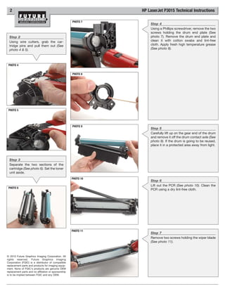
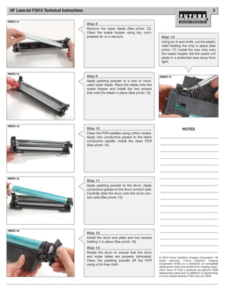
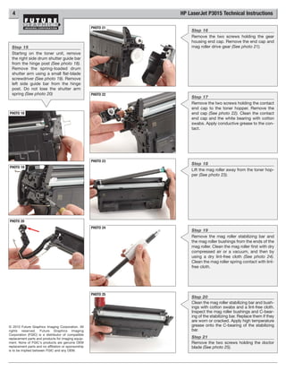
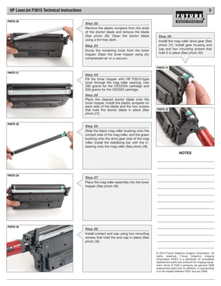
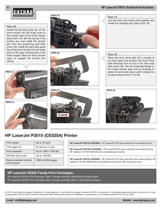

The document provides technical instructions for replacing components in an HP LaserJet P3015 printer, including removing the drum drive axle, cartridge pins, separating the cartridge, removing the wiper blade, photoconductor roller (PCR), chip, cleaning various parts, applying new grease and reinstalling components. Over 14 steps are outlined with accompanying photos to illustrate the process.


