Download to read offline
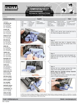
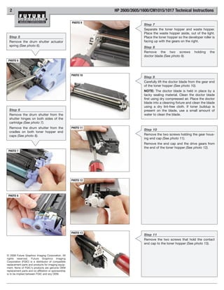
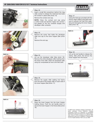
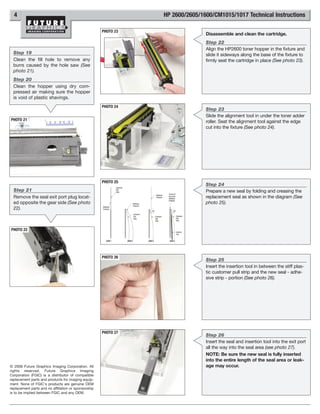
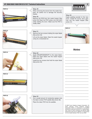
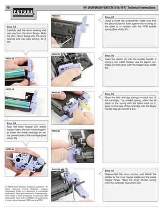
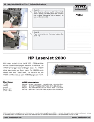

This document provides technical instructions for disassembling and cleaning an HP2600 toner cartridge. It consists of 44 steps with accompanying photos detailing how to remove individual parts like the drum, toner hopper, doctor blade, and seals. The instructions also describe using various tools and fixtures to facilitate disassembly and reassembly. The overall goal is to properly disassemble, clean, and reassemble the toner cartridge.


