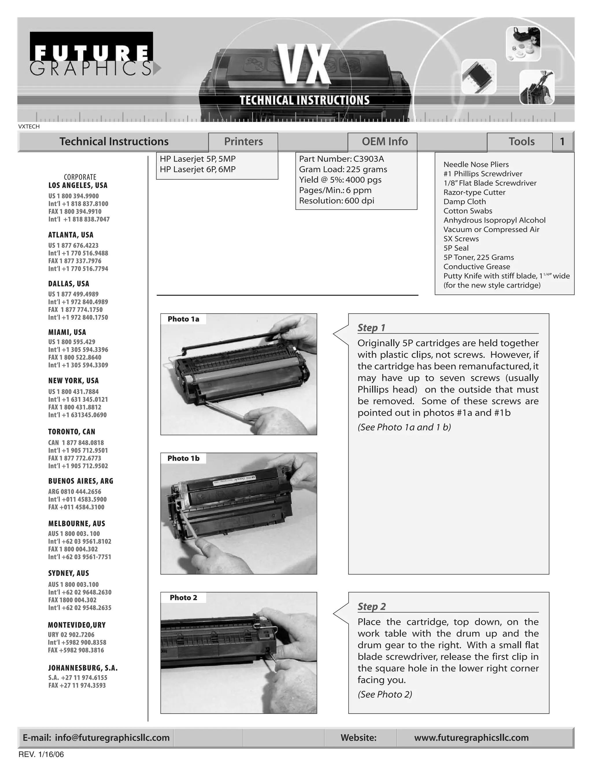
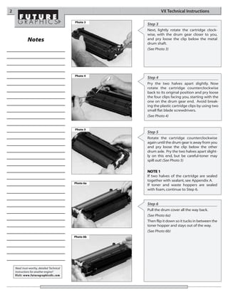
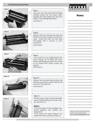
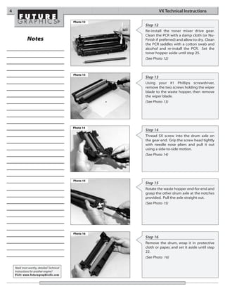
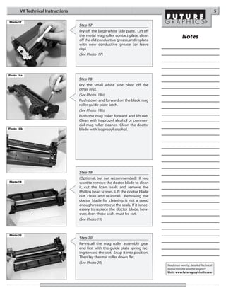
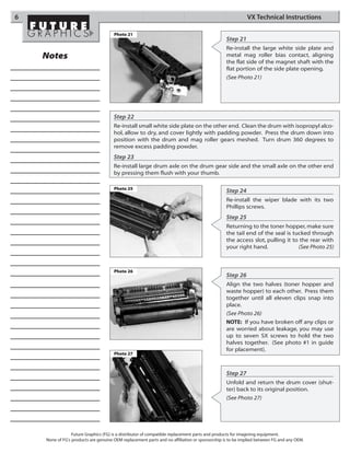
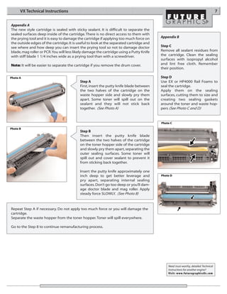
VXTECH

            Technical Instructions                Printers                 OEM Info                                 Tools           1
                                  HP Laserjet 5P, 5MP        Part Number: C3903A
                                                                                                Needle Nose Pliers
                                  HP Laserjet 6P, 6MP        Gram Load: 225 grams               #1 Phillips Screwdriver
             CORPORATE                                       Yield @ 5%: 4000 pgs
         LOS ANGELES, USA                                                                       1/8” Flat Blade Screwdriver
                                                             Pages/Min.: 6 ppm                  Razor-type Cutter
         US 1 800 394.9900
         Int’l +1 818 837.8100                               Resolution: 600 dpi                Damp Cloth
         FAX 1 800 394.9910                                                                     Cotton Swabs
         Int’l +1 818 838.7047                                                                  Anhydrous Isopropyl Alcohol
                                                                                                Vacuum or Compressed Air
         ATLANTA, USA                                                                           SX Screws
         US 1 877 676.4223                                                                      5P Seal
         Int’l +1 770 516.9488
         FAX 1 877 337.7976                                                                     5P Toner, 225 Grams
         Int’l +1 770 516.7794                                                                  Conductive Grease
                                                                                                Putty Knife with stiff blade, 11/4” wide
         DALLAS, USA                                                                            (for the new style cartridge)
         US 1 877 499.4989
         Int’l +1 972 840.4989
         FAX 1 877 774.1750
         Int’l +1 972 840.1750     Photo 1a
         MIAMI, USA                                                       Step 1
         US 1 800 595.429                                                 Originally 5P cartridges are held together
         Int’l +1 305 594.3396
         FAX 1 800 522.8640                                               with plastic clips, not screws. However, if
         Int’l +1 305 594.3309                                            the cartridge has been remanufactured, it
         NEW YORK, USA                                                    may have up to seven screws (usually
         US 1 800 431.7884                                                Phillips head) on the outside that must
         Int’l +1 631 345.0121                                            be removed. Some of these screws are
         FAX 1 800 431.8812
         Int’l +1 631345.0690                                             pointed out in photos #1a and #1b
         TORONTO, CAN                                                     (See Photo 1a and 1 b)
         CAN 1 877 848.0818
         Int’l +1 905 712.9501
         FAX 1 877 772.6773        Photo 1b
         Int’l +1 905 712.9502

         BUENOS AIRES, ARG
         ARG 0810 444.2656
         Int’l +011 4583.5900
         FAX +011 4584.3100

         MELBOURNE, AUS
         AUS 1 800 003. 100
         Int’l +62 03 9561.8102
         FAX 1 800 004.302
         Int’l +62 03 9561-7751

         SYDNEY, AUS
         AUS 1 800 003.100
         Int’l +62 02 9648.2630
         FAX 1800 004.302            Photo 2
         Int’l +62 02 9548.2635                                           Step 2
         MONTEVIDEO,URY                                                   Place the cartridge, top down, on the
         URY 02 902.7206                                                  work table with the drum up and the
         Int’l +5982 900.8358                                             drum gear to the right. With a small flat
         FAX +5982 908.3816
                                                                          blade screwdriver, release the first clip in
         JOHANNESBURG, S.A.                                               the square hole in the lower right corner
         S.A. +27 11 974.6155                                             facing you.
         FAX +27 11 974.3593
                                                                          (See Photo 2)


 E-mail: info@futuregraphicsllc.com                                   Website:            www.futuregraphicsllc.com
REV. 1/16/06
2                                                               VX Technical Instructions

                                            Photo 3
                                                       Step 3
                                                       Next, lightly rotate the cartridge clock-
                                                       wise, with the drum gear closer to you,
              Notes                                    and pry loose the clip below the metal
                                                       drum shaft.
                                                       (See Photo 3)


                                            Photo 4
                                                       Step 4
                                                       Pry the two halves apart slightly. Now
                                                       rotate the cartridge counterclockwise
                                                       back to its original position and pry loose
                                                       the four clips facing you, starting with the
                                                       one on the drum gear end. Avoid break-
                                                       ing the plastic cartridge clips by using two
                                                       small flat blade screwdrivers.
                                                       (See Photo 4)


                                            Photo 5
                                                       Step 5
                                                       Rotate the cartridge counterclockwise
                                                       again until the drum gear is away from you
                                                       and pry loose the clip below the other
                                                       drum axle. Pry the two halves apart slight-
                                                       ly on this end, but be careful-toner may
                                                       spill out! (See Photo 5)

                                                       NOTE 1
                                                       If two halves of the cartridge are sealed
                                                       together with sealant, see Appendix A.
                                            Photo 6a
                                                       If toner and waste hoppers are sealed
                                                       with foam, continue to Step 6.


                                                       Step 6
                                                       Pull the drum cover all the way back.
                                                       (See Photo 6a)
                                                       Then flip it down so it tucks in between the
                                                       toner hopper and stays out of the way.
                                                       (See Photo 6b)
                                            Photo 6b


    Need trust-worthy, detailed Technical
    Instructions for another engine?
    Visit: www.futuregraphicsllc.com
VX Technical Instructions                                                                                          3

Photo 7
                                   Step 7
                                   Now, work your way around the cartridge,
                                   carefully prying the two halves apart.
                                   Separate the waste hopper from the toner
                                                                                              Notes
                                   hopper. Toner will spill everywhere.
                                   (See Photo 7)


Photo 8
                                   Step 8
                                   Remove the toner mixing drive gear and
                                   PCR from the toner hopper and set them
                                   aside. Dump the toner out and clean
                                   thoroughly with a vacuum or com-
                                   pressed air.
                                   (See Photo 8)


Photo 9
                                   Step 9
                                   A new seal has to be installed before the
                                   toner hopper can be filled with toner.
                                   Remove the fill plug and clean the surface
                                   to be sealed with cotton swabs and
                                   alcohol.
                                   (See Photo 9)


Photo 10
                                   Step 10
                                   Remove the non-stick backing from the
                                   adhesive seal and lay in place with the tail
                                   away from the plug end.
                                   (See Photo10)


                                   Step 11
Photo 11                           Fill with toner using a funnel cap bottle
                                   and re-install the plug in the toner hop-
                                   per. (See Photo11)

                                   NOTE 2
                                   If the two halves of the cartridge were
                                   sealed together with sealant, see
                                   Appendix B.                                    Need trust-worthy, detailed Technical
                                                                                  Instructions for another engine?
                                   If the toner and waste hoppers are             Visit: www.futuregraphicsllc.com
                                   sealed with foam, continue to Step 12.
4                                                                VX Technical Instructions

                                            Photo 12
                                                       Step 12
                                                       Re-install the toner mixer drive gear.
                                                       Clean the PCR with a damp cloth (or Nu-
              Notes                                    Finish if preferred) and allow to dry. Clean
                                                       the PCR saddles with a cotton swab and
                                                       alcohol and re-install the PCR. Set the
                                                       toner hopper aside until step 25.
                                                       (See Photo 12)


                                            Photo 13
                                                       Step 13
                                                       Using your #1 Phillips screwdriver,
                                                       remove the two screws holding the wiper
                                                       blade to the waste hopper, then remove
                                                       the wiper blade.
                                                       (See Photo 13)


                                            Photo 14
                                                       Step 14
                                                       Thread SX screw into the drum axle on
                                                       the gear end. Grip the screw head tightly
                                                       with needle nose pliers and pull it out
                                                       using a side-to-side motion.
                                                       (See Photo 14)


                                            Photo 15
                                                       Step 15
                                                       Rotate the waste hopper end-for-end and
                                                       grasp the other drum axle at the notches
                                                       provided. Pull the axle straight out.
                                                       (See Photo 15)


                                            Photo 16
                                                       Step 16
                                                       Remove the drum, wrap it in protective
                                                       cloth or paper, and set it aside until step
                                                       22.
                                                       (See Photo 16)

    Need trust-worthy, detailed Technical
    Instructions for another engine?
    Visit: www.futuregraphicsllc.com
VX Technical Instructions                                                                                           5

Photo 17
                                   Step 17
                                   Pry off the large white side plate. Lift off
                                   the metal mag roller contact plate, clean                   Notes
                                   off the old conductive grease, and replace
                                   with new conductive grease (or leave
                                   dry).
                                   (See Photo 17)


Photo 18a
                                   Step 18
                                   Pry the small white side plate off the
                                   other end.
                                   (See Photo 18a)
                                   Push down and forward on the black mag
                                   roller guide plate latch.
                                   (See Photo 18b)
                                   Push the mag roller forward and lift out.
                                   Clean with isopropyl alcohol or commer-
                                   cial mag roller cleaner. Clean the doctor
Photo 18b                          blade with isopropyl alcohol.


                                   Step 19
                                   (Optional, but not recommended) If you
Photo 19                           want to remove the doctor blade to clean
                                   it, cut the foam seals and remove the
                                   Phillips head screws. Lift the doctor blade
                                   out, clean and re-install. Removing the
                                   doctor blade for cleaning is not a good
                                   enough reason to cut the seals. If it is nec-
                                   essary to replace the doctor blade, how-
                                   ever, then these seals must be cut.
                                   (See Photo 19)


Photo 20
                                   Step 20
                                   Re-install the mag roller assembly gear
                                   end first with the guide plate spring fac-
                                   ing toward the slot. Snap it into position.
                                   Then lay thermal roller down flat.
                                   (See Photo 20)
                                                                                   Need trust-worthy, detailed Technical
                                                                                   Instructions for another engine?
                                                                                   Visit: www.futuregraphicsllc.com
6                                                                                                        VX Technical Instructions

                                      Photo 21
                                                                                              Step 21
                                                                                              Re-install the large white side plate and
    Notes                                                                                     metal mag roller bias contact, aligning
                                                                                              the flat side of the magnet shaft with the
                                                                                              flat portion of the side plate opening.
                                                                                              (See Photo 21)


                                      Step 22
                                      Re-install small white side plate on the other end. Clean the drum with isopropyl alco-
                                      hol, allow to dry, and cover lightly with padding powder. Press the drum down into
                                      position with the drum and mag roller gears meshed. Turn drum 360 degrees to
                                      remove excess padding powder.
                                      Step 23
                                      Re-install large drum axle on the drum gear side and the small axle on the other end
                                      by pressing them flush with your thumb.

                                      Photo 25
                                                                                              Step 24
                                                                                              Re-install the wiper blade with its two
                                                                                              Phillips screws.
                                                                                              Step 25
                                                                                              Returning to the toner hopper, make sure
                                                                                              the tail end of the seal is tucked through
                                                                                              the access slot, pulling it to the rear with
                                                                                              your right hand.              (See Photo 25)


                                      Photo 26
                                                                                              Step 26
                                                                                              Align the two halves (toner hopper and
                                                                                              waste hopper) to each other. Press them
                                                                                              together until all eleven clips snap into
                                                                                              place.
                                                                                              (See Photo 26)
                                                                                              NOTE: If you have broken off any clips or
                                                                                              are worried about leakage, you may use
                                                                                              up to seven SX screws to hold the two
                                                                                              halves together. (See photo #1 in guide
                                                                                              for placement).
                                      Photo 27


                                                                                              Step 27
                                                                                              Unfold and return the drum cover (shut-
                                                                                              ter) back to its original position.
                                                                                              (See Photo 27)


                 Future Graphics (FG) is a distributor of compatible replacement parts and products for imagining equipment.
    None of FG's products are genuine OEM replacement parts and no affiliation or sponsorship is to be implied between FG and any OEM.
VX Technical Instructions                                                                                                       7


Appendix A
The new style cartridge is sealed with sticky sealant. It is difficult to separate the
sealed surfaces deep inside of the cartridge. There is no direct access to them with
the prying tool and it is easy to damage the cartridge if applying too much force on      Appendix B
the outside edges of the cartridge. It is useful to look at the separated cartridge and
see where and how deep you can insert the prying tool so not to damage doctor             Step C
blade, mag roller or PCR.You will less likely damage the cartridge using a Putty Knife    Remove all sealant residues from
with stiff blade 1 1/4 inches wide as a prying tool than with a screwdriver.              the cartridge. Clean the sealing
                                                                                          surfaces with isopropyl alcohol
Note: It will be easier to separate the cartridge if you remove the drum cover.           and lint free cloth. Remember
                                                                                          their position.

Photo A                                                                                   Step D
                                           Step A                                         Use EX or HP4000 Rail Foams to
                                           First, insert the putty knife blade between    seal the cartridge.
                                           the two halves of the cartridge on the         Apply them on the sealing
                                           waste hopper side and slowly pry them          surfaces, cutting them to size and
                                           apart. Some toner will spill out on the        creating two sealing gaskets
                                           sealant and they will not stick back           around the toner and waste hop-
                                           together. (See Photo A)                        pers (See Photo C and D)


                                                                                          Photo C
Photo B
                                           Step B
                                           Then insert the putty knife blade
                                           between the two halves of the cartridge
                                           on the toner hopper side of the cartridge
                                           and slowly pry them apart, separating the
                                           outer sealing surfaces. Some toner will
                                           spill out and cover sealant to prevent it
                                           from sticking back together.

                                           Insert the putty knife approximately one
                                           inch deep to get better leverage and           Photo D
                                           pry apart, separating internal sealing
                                           surfaces. Don’t go too deep or you’ll dam-
                                           age doctor blade and mag roller. Apply
                                           steady force SLOWLY. (See Photo B)


Repeat Step A if necessary. Do not apply too much force or you will damage the
cartridge.
Separate the waste hopper from the toner hopper. Toner will spill everywhere.

Go to the Step 8 to continue remanufacturing process.


                                                                                              Need trust-worthy, detailed Technical
                                                                                              Instructions for another engine?
                                                                                              Visit: www.futuregraphicsllc.com

Manual de Recarga HP Canon VX C3903A.

  • 1.
    VXTECH Technical Instructions Printers OEM Info Tools 1 HP Laserjet 5P, 5MP Part Number: C3903A Needle Nose Pliers HP Laserjet 6P, 6MP Gram Load: 225 grams #1 Phillips Screwdriver CORPORATE Yield @ 5%: 4000 pgs LOS ANGELES, USA 1/8” Flat Blade Screwdriver Pages/Min.: 6 ppm Razor-type Cutter US 1 800 394.9900 Int’l +1 818 837.8100 Resolution: 600 dpi Damp Cloth FAX 1 800 394.9910 Cotton Swabs Int’l +1 818 838.7047 Anhydrous Isopropyl Alcohol Vacuum or Compressed Air ATLANTA, USA SX Screws US 1 877 676.4223 5P Seal Int’l +1 770 516.9488 FAX 1 877 337.7976 5P Toner, 225 Grams Int’l +1 770 516.7794 Conductive Grease Putty Knife with stiff blade, 11/4” wide DALLAS, USA (for the new style cartridge) US 1 877 499.4989 Int’l +1 972 840.4989 FAX 1 877 774.1750 Int’l +1 972 840.1750 Photo 1a MIAMI, USA Step 1 US 1 800 595.429 Originally 5P cartridges are held together Int’l +1 305 594.3396 FAX 1 800 522.8640 with plastic clips, not screws. However, if Int’l +1 305 594.3309 the cartridge has been remanufactured, it NEW YORK, USA may have up to seven screws (usually US 1 800 431.7884 Phillips head) on the outside that must Int’l +1 631 345.0121 be removed. Some of these screws are FAX 1 800 431.8812 Int’l +1 631345.0690 pointed out in photos #1a and #1b TORONTO, CAN (See Photo 1a and 1 b) CAN 1 877 848.0818 Int’l +1 905 712.9501 FAX 1 877 772.6773 Photo 1b Int’l +1 905 712.9502 BUENOS AIRES, ARG ARG 0810 444.2656 Int’l +011 4583.5900 FAX +011 4584.3100 MELBOURNE, AUS AUS 1 800 003. 100 Int’l +62 03 9561.8102 FAX 1 800 004.302 Int’l +62 03 9561-7751 SYDNEY, AUS AUS 1 800 003.100 Int’l +62 02 9648.2630 FAX 1800 004.302 Photo 2 Int’l +62 02 9548.2635 Step 2 MONTEVIDEO,URY Place the cartridge, top down, on the URY 02 902.7206 work table with the drum up and the Int’l +5982 900.8358 drum gear to the right. With a small flat FAX +5982 908.3816 blade screwdriver, release the first clip in JOHANNESBURG, S.A. the square hole in the lower right corner S.A. +27 11 974.6155 facing you. FAX +27 11 974.3593 (See Photo 2) E-mail: info@futuregraphicsllc.com Website: www.futuregraphicsllc.com REV. 1/16/06
  • 2.
    2 VX Technical Instructions Photo 3 Step 3 Next, lightly rotate the cartridge clock- wise, with the drum gear closer to you, Notes and pry loose the clip below the metal drum shaft. (See Photo 3) Photo 4 Step 4 Pry the two halves apart slightly. Now rotate the cartridge counterclockwise back to its original position and pry loose the four clips facing you, starting with the one on the drum gear end. Avoid break- ing the plastic cartridge clips by using two small flat blade screwdrivers. (See Photo 4) Photo 5 Step 5 Rotate the cartridge counterclockwise again until the drum gear is away from you and pry loose the clip below the other drum axle. Pry the two halves apart slight- ly on this end, but be careful-toner may spill out! (See Photo 5) NOTE 1 If two halves of the cartridge are sealed together with sealant, see Appendix A. Photo 6a If toner and waste hoppers are sealed with foam, continue to Step 6. Step 6 Pull the drum cover all the way back. (See Photo 6a) Then flip it down so it tucks in between the toner hopper and stays out of the way. (See Photo 6b) Photo 6b Need trust-worthy, detailed Technical Instructions for another engine? Visit: www.futuregraphicsllc.com
  • 3.
    VX Technical Instructions 3 Photo 7 Step 7 Now, work your way around the cartridge, carefully prying the two halves apart. Separate the waste hopper from the toner Notes hopper. Toner will spill everywhere. (See Photo 7) Photo 8 Step 8 Remove the toner mixing drive gear and PCR from the toner hopper and set them aside. Dump the toner out and clean thoroughly with a vacuum or com- pressed air. (See Photo 8) Photo 9 Step 9 A new seal has to be installed before the toner hopper can be filled with toner. Remove the fill plug and clean the surface to be sealed with cotton swabs and alcohol. (See Photo 9) Photo 10 Step 10 Remove the non-stick backing from the adhesive seal and lay in place with the tail away from the plug end. (See Photo10) Step 11 Photo 11 Fill with toner using a funnel cap bottle and re-install the plug in the toner hop- per. (See Photo11) NOTE 2 If the two halves of the cartridge were sealed together with sealant, see Appendix B. Need trust-worthy, detailed Technical Instructions for another engine? If the toner and waste hoppers are Visit: www.futuregraphicsllc.com sealed with foam, continue to Step 12.
  • 4.
    4 VX Technical Instructions Photo 12 Step 12 Re-install the toner mixer drive gear. Clean the PCR with a damp cloth (or Nu- Notes Finish if preferred) and allow to dry. Clean the PCR saddles with a cotton swab and alcohol and re-install the PCR. Set the toner hopper aside until step 25. (See Photo 12) Photo 13 Step 13 Using your #1 Phillips screwdriver, remove the two screws holding the wiper blade to the waste hopper, then remove the wiper blade. (See Photo 13) Photo 14 Step 14 Thread SX screw into the drum axle on the gear end. Grip the screw head tightly with needle nose pliers and pull it out using a side-to-side motion. (See Photo 14) Photo 15 Step 15 Rotate the waste hopper end-for-end and grasp the other drum axle at the notches provided. Pull the axle straight out. (See Photo 15) Photo 16 Step 16 Remove the drum, wrap it in protective cloth or paper, and set it aside until step 22. (See Photo 16) Need trust-worthy, detailed Technical Instructions for another engine? Visit: www.futuregraphicsllc.com
  • 5.
    VX Technical Instructions 5 Photo 17 Step 17 Pry off the large white side plate. Lift off the metal mag roller contact plate, clean Notes off the old conductive grease, and replace with new conductive grease (or leave dry). (See Photo 17) Photo 18a Step 18 Pry the small white side plate off the other end. (See Photo 18a) Push down and forward on the black mag roller guide plate latch. (See Photo 18b) Push the mag roller forward and lift out. Clean with isopropyl alcohol or commer- cial mag roller cleaner. Clean the doctor Photo 18b blade with isopropyl alcohol. Step 19 (Optional, but not recommended) If you Photo 19 want to remove the doctor blade to clean it, cut the foam seals and remove the Phillips head screws. Lift the doctor blade out, clean and re-install. Removing the doctor blade for cleaning is not a good enough reason to cut the seals. If it is nec- essary to replace the doctor blade, how- ever, then these seals must be cut. (See Photo 19) Photo 20 Step 20 Re-install the mag roller assembly gear end first with the guide plate spring fac- ing toward the slot. Snap it into position. Then lay thermal roller down flat. (See Photo 20) Need trust-worthy, detailed Technical Instructions for another engine? Visit: www.futuregraphicsllc.com
  • 6.
    6 VX Technical Instructions Photo 21 Step 21 Re-install the large white side plate and Notes metal mag roller bias contact, aligning the flat side of the magnet shaft with the flat portion of the side plate opening. (See Photo 21) Step 22 Re-install small white side plate on the other end. Clean the drum with isopropyl alco- hol, allow to dry, and cover lightly with padding powder. Press the drum down into position with the drum and mag roller gears meshed. Turn drum 360 degrees to remove excess padding powder. Step 23 Re-install large drum axle on the drum gear side and the small axle on the other end by pressing them flush with your thumb. Photo 25 Step 24 Re-install the wiper blade with its two Phillips screws. Step 25 Returning to the toner hopper, make sure the tail end of the seal is tucked through the access slot, pulling it to the rear with your right hand. (See Photo 25) Photo 26 Step 26 Align the two halves (toner hopper and waste hopper) to each other. Press them together until all eleven clips snap into place. (See Photo 26) NOTE: If you have broken off any clips or are worried about leakage, you may use up to seven SX screws to hold the two halves together. (See photo #1 in guide for placement). Photo 27 Step 27 Unfold and return the drum cover (shut- ter) back to its original position. (See Photo 27) Future Graphics (FG) is a distributor of compatible replacement parts and products for imagining equipment. None of FG's products are genuine OEM replacement parts and no affiliation or sponsorship is to be implied between FG and any OEM.
  • 7.
    VX Technical Instructions 7 Appendix A The new style cartridge is sealed with sticky sealant. It is difficult to separate the sealed surfaces deep inside of the cartridge. There is no direct access to them with the prying tool and it is easy to damage the cartridge if applying too much force on Appendix B the outside edges of the cartridge. It is useful to look at the separated cartridge and see where and how deep you can insert the prying tool so not to damage doctor Step C blade, mag roller or PCR.You will less likely damage the cartridge using a Putty Knife Remove all sealant residues from with stiff blade 1 1/4 inches wide as a prying tool than with a screwdriver. the cartridge. Clean the sealing surfaces with isopropyl alcohol Note: It will be easier to separate the cartridge if you remove the drum cover. and lint free cloth. Remember their position. Photo A Step D Step A Use EX or HP4000 Rail Foams to First, insert the putty knife blade between seal the cartridge. the two halves of the cartridge on the Apply them on the sealing waste hopper side and slowly pry them surfaces, cutting them to size and apart. Some toner will spill out on the creating two sealing gaskets sealant and they will not stick back around the toner and waste hop- together. (See Photo A) pers (See Photo C and D) Photo C Photo B Step B Then insert the putty knife blade between the two halves of the cartridge on the toner hopper side of the cartridge and slowly pry them apart, separating the outer sealing surfaces. Some toner will spill out and cover sealant to prevent it from sticking back together. Insert the putty knife approximately one inch deep to get better leverage and Photo D pry apart, separating internal sealing surfaces. Don’t go too deep or you’ll dam- age doctor blade and mag roller. Apply steady force SLOWLY. (See Photo B) Repeat Step A if necessary. Do not apply too much force or you will damage the cartridge. Separate the waste hopper from the toner hopper. Toner will spill everywhere. Go to the Step 8 to continue remanufacturing process. Need trust-worthy, detailed Technical Instructions for another engine? Visit: www.futuregraphicsllc.com