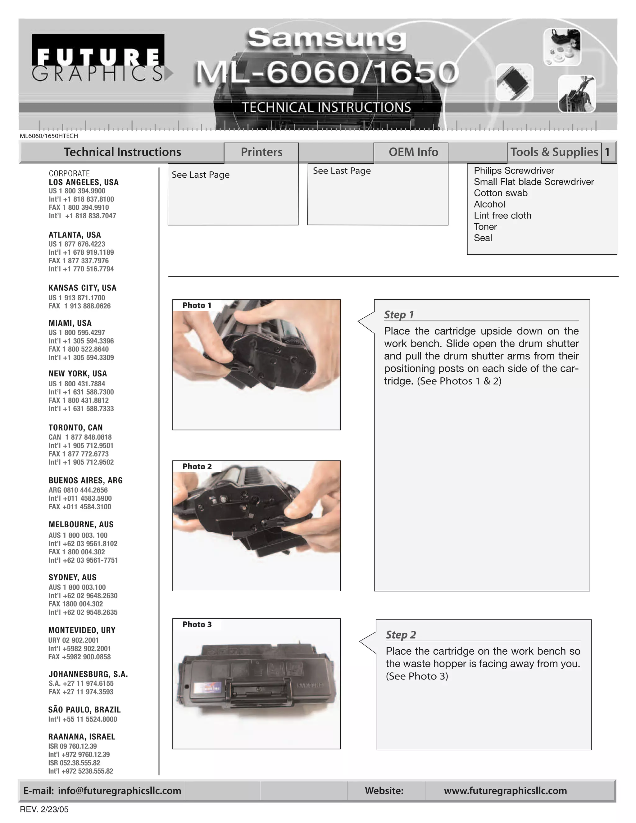
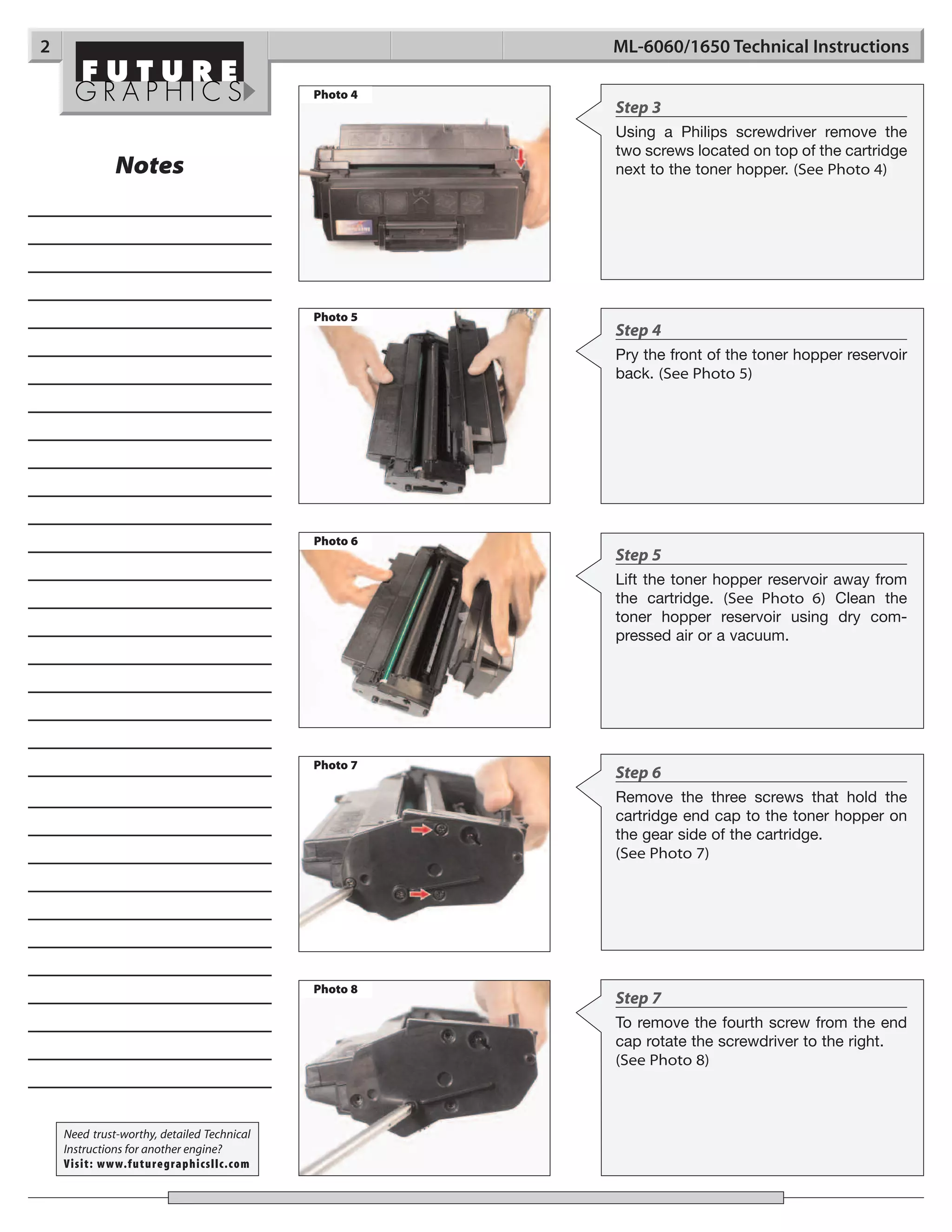
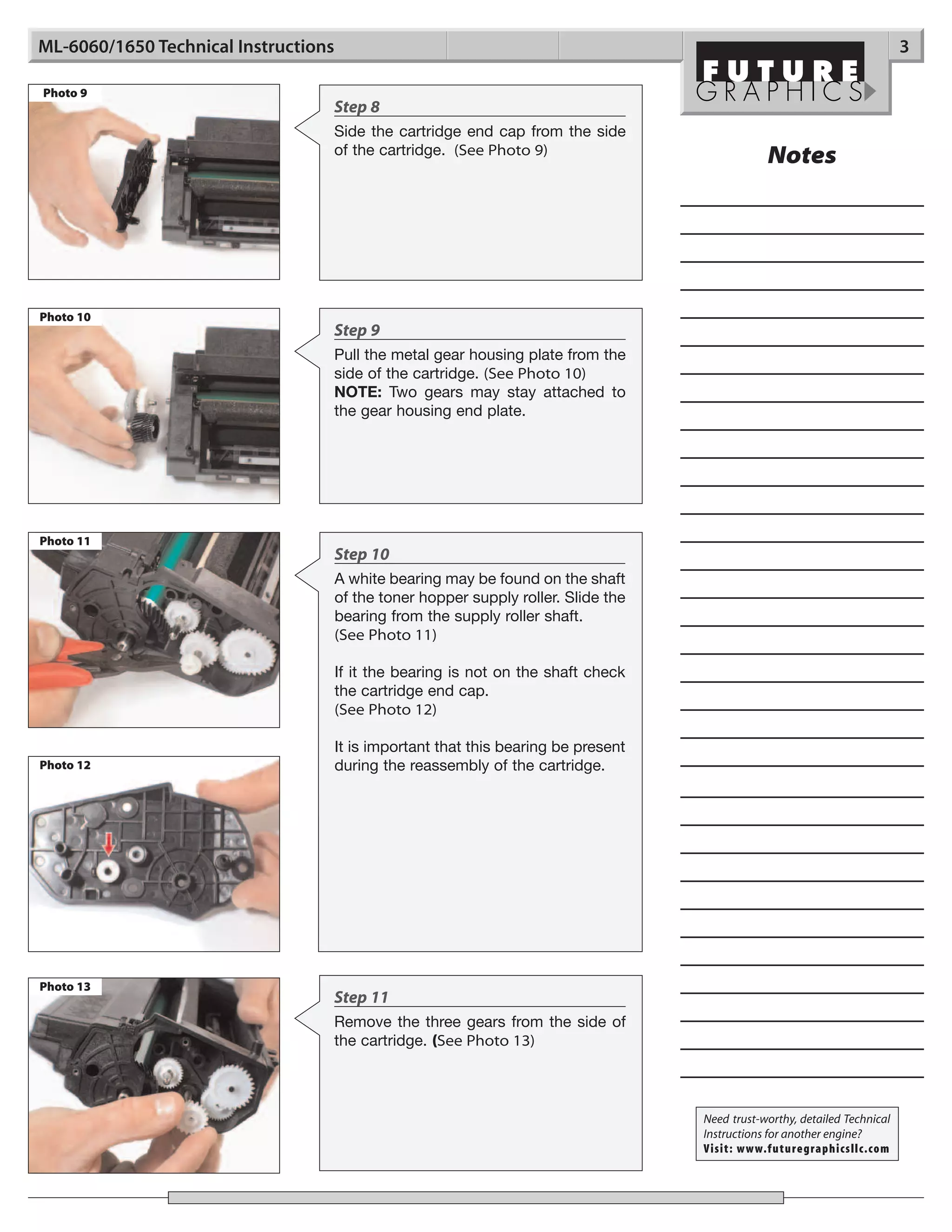
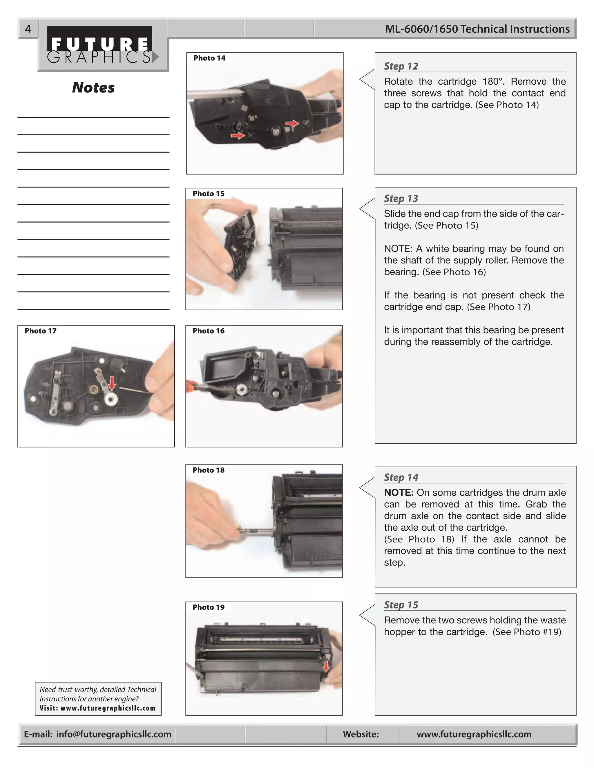
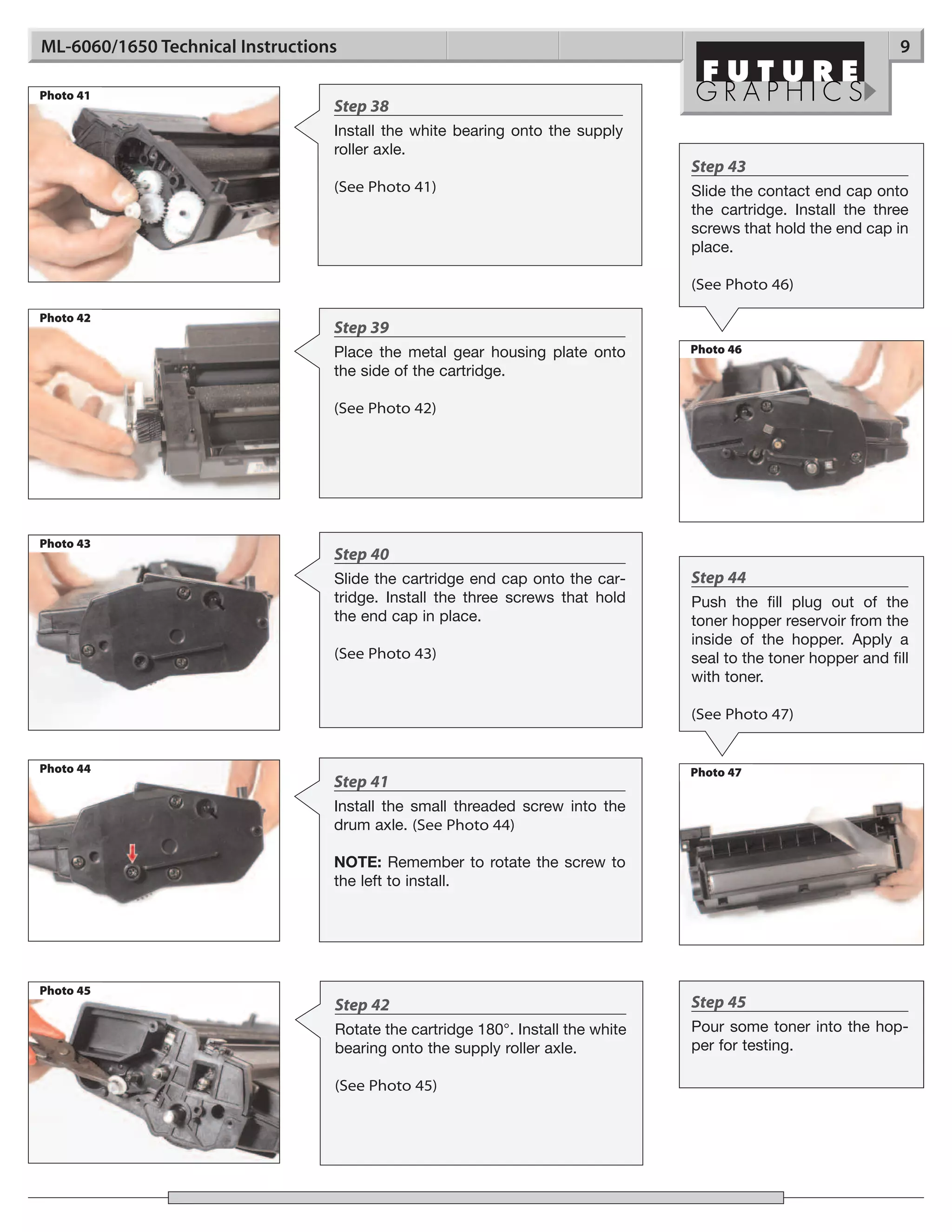
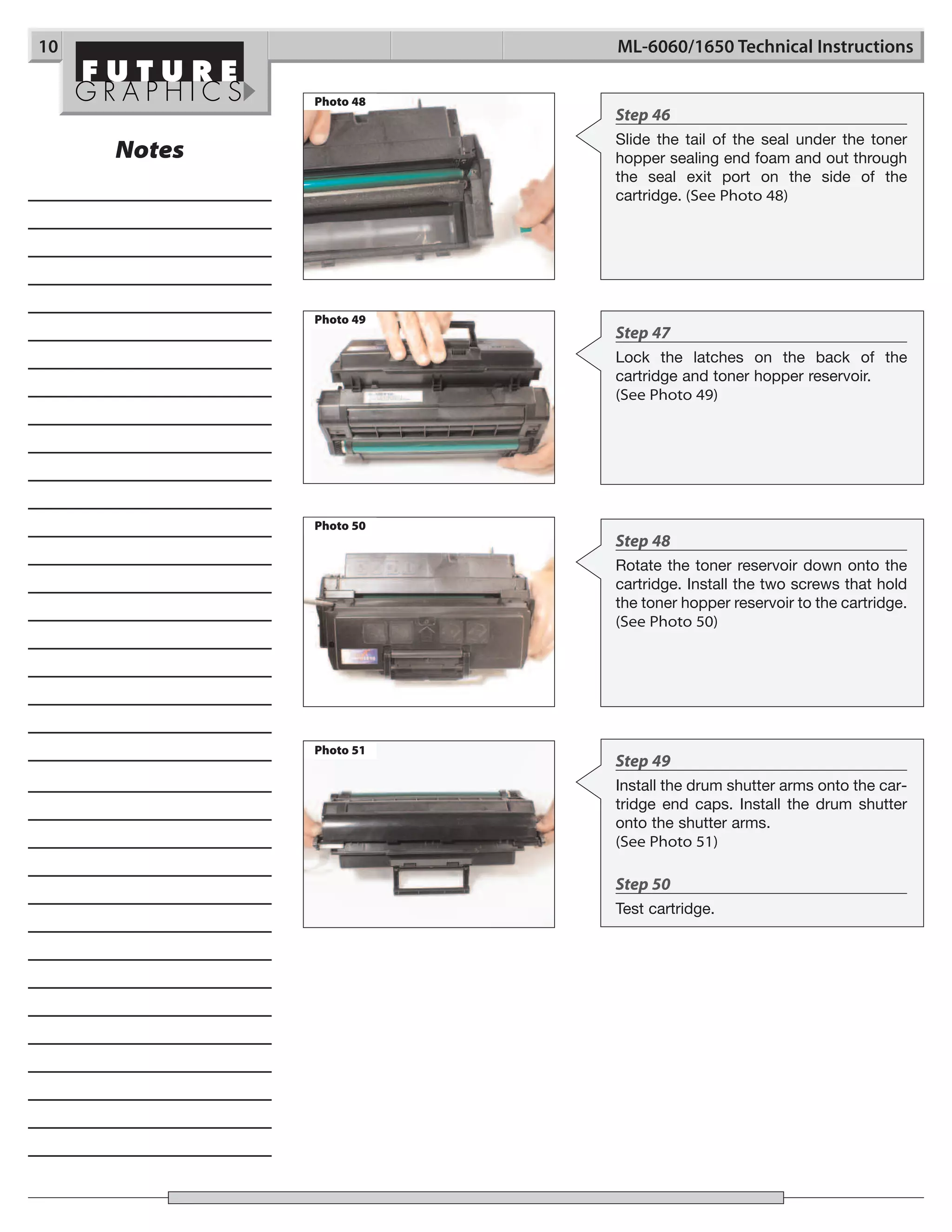
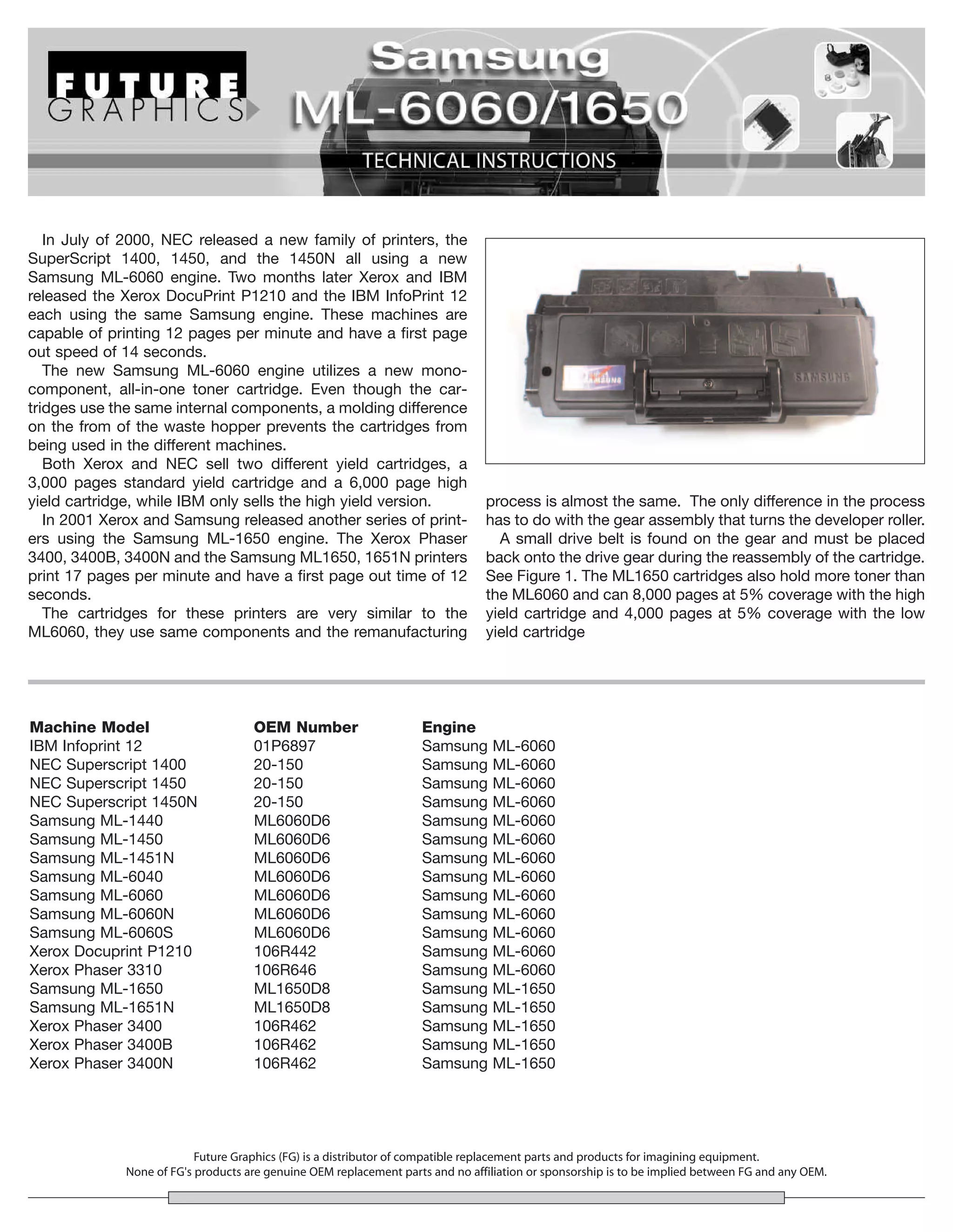
ML6060/1650HTECH

            Technical Instructions              Printers                    OEM Info                  Tools & Supplies 1
        CORPORATE               See Last Page              See Last Page                      Philips Screwdriver
        LOS ANGELES, USA                                                                      Small Flat blade Screwdriver
        US 1 800 394.9900                                                                     Cotton swab
        Int’l +1 818 837.8100
        FAX 1 800 394.9910                                                                    Alcohol
        Int’l +1 818 838.7047                                                                 Lint free cloth
                                                                                              Toner
       ATLANTA, USA                                                                           Seal
       US 1 877 676.4223
       Int’l +1 678 919.1189
       FAX 1 877 337.7976
       Int’l +1 770 516.7794

       KANSAS CITY, USA
       US 1 913 871.1700
       FAX 1 913 888.0626            Photo 1
                                                                           Step 1
       MIAMI, USA
       US 1 800 595.4297                                                   Place the cartridge upside down on the
       Int’l +1 305 594.3396
       FAX 1 800 522.8640
                                                                           work bench. Slide open the drum shutter
       Int’l +1 305 594.3309                                               and pull the drum shutter arms from their
       NEW YORK, USA
                                                                           positioning posts on each side of the car-
       US 1 800 431.7884                                                   tridge. (See Photos 1 & 2)
       Int’l +1 631 588.7300
       FAX 1 800 431.8812
       Int’l +1 631 588.7333

       TORONTO, CAN
       CAN 1 877 848.0818
       Int’l +1 905 712.9501
       FAX 1 877 772.6773
       Int’l +1 905 712.9502
                                     Photo 2
       BUENOS AIRES, ARG
       ARG 0810 444.2656
       Int’l +011 4583.5900
       FAX +011 4584.3100

       MELBOURNE, AUS
       AUS 1 800 003. 100
       Int’l +62 03 9561.8102
       FAX 1 800 004.302
       Int’l +62 03 9561-7751

       SYDNEY, AUS
       AUS 1 800 003.100
       Int’l +62 02 9648.2630
       FAX 1800 004.302
       Int’l +62 02 9548.2635
                                     Photo 3
       MONTEVIDEO, URY
       URY 02 902.2001
                                                                           Step 2
       Int’l +5982 902.2001                                                Place the cartridge on the work bench so
       FAX +5982 900.0858
                                                                           the waste hopper is facing away from you.
       JOHANNESBURG, S.A.                                                  (See Photo 3)
        S.A. +27 11 974.6155
        FAX +27 11 974.3593

       SÃO PAULO, BRAZIL
       Int’l +55 11 5524.8000

       RAANANA, ISRAEL
       ISR 09 760.12.39
       Int’l +972 9760.12.39
       ISR 052.38.555.82
       Int’l +972 5238.555.82

E-mail: info@futuregraphicsllc.com                                    Website:         www.futuregraphicsllc.com
REV. 2/23/05
2                                                     ML-6060/1650 Technical Instructions

                                            Photo 4
                                                      Step 3
                                                      Using a Philips screwdriver remove the
                                                      two screws located on top of the cartridge
              Notes                                   next to the toner hopper. (See Photo 4)


                                            Photo 5
                                                      Step 4
                                                      Pry the front of the toner hopper reservoir
                                                      back. (See Photo 5)


                                            Photo 6
                                                      Step 5
                                                      Lift the toner hopper reservoir away from
                                                      the cartridge. (See Photo 6) Clean the
                                                      toner hopper reservoir using dry com-
                                                      pressed air or a vacuum.


                                            Photo 7
                                                      Step 6
                                                      Remove the three screws that hold the
                                                      cartridge end cap to the toner hopper on
                                                      the gear side of the cartridge.
                                                      (See Photo 7)


                                            Photo 8
                                                      Step 7
                                                      To remove the fourth screw from the end
                                                      cap rotate the screwdriver to the right.
                                                      (See Photo 8)


    Need trust-worthy, detailed Technical
    Instructions for another engine?
    Visit: www.futuregraphicsllc.com
ML-6060/1650 Technical Instructions                                                                                          3

Photo 9
                                  Step 8
                                  Side the cartridge end cap from the side
                                  of the cartridge. (See Photo 9)
                                                                                                 Notes


Photo 10
                                  Step 9
                                  Pull the metal gear housing plate from the
                                  side of the cartridge. (See Photo 10)
                                  NOTE: Two gears may stay attached to
                                  the gear housing end plate.


Photo 11
                                      Step 10
                                      A white bearing may be found on the shaft
                                      of the toner hopper supply roller. Slide the
                                      bearing from the supply roller shaft.
                                      (See Photo 11)

                                      If it the bearing is not on the shaft check
                                      the cartridge end cap.
                                      (See Photo 12)

                                      It is important that this bearing be present
Photo 12                              during the reassembly of the cartridge.


Photo 13
                                  Step 11
                                  Remove the three gears from the side of
                                  the cartridge. (See Photo 13)


                                                                                     Need trust-worthy, detailed Technical
                                                                                     Instructions for another engine?
                                                                                     Visit: www.futuregraphicsllc.com
4                                                                 ML-6060/1650 Technical Instructions

                                            Photo 14
                                                                  Step 12
                                                                  Rotate the cartridge 180°. Remove the
              Notes                                               three screws that hold the contact end
                                                                  cap to the cartridge. (See Photo 14)


                                            Photo 15
                                                                  Step 13
                                                                  Slide the end cap from the side of the car-
                                                                  tridge. (See Photo 15)

                                                                  NOTE: A white bearing may be found on
                                                                  the shaft of the supply roller. Remove the
                                                                  bearing. (See Photo 16)

                                                                  If the bearing is not present check the
                                                                  cartridge end cap. (See Photo 17)

Photo 17                                    Photo 16              It is important that this bearing be present
                                                                  during the reassembly of the cartridge.


                                            Photo 18
                                                                  Step 14
                                                                  NOTE: On some cartridges the drum axle
                                                                  can be removed at this time. Grab the
                                                                  drum axle on the contact side and slide
                                                                  the axle out of the cartridge.
                                                                  (See Photo 18) If the axle cannot be
                                                                  removed at this time continue to the next
                                                                  step.


                                            Photo 19              Step 15
                                                                  Remove the two screws holding the waste
                                                                  hopper to the cartridge. (See Photo #19)


    Need trust-worthy, detailed Technical
    Instructions for another engine?
    Visit: www.futuregraphicsllc.com


E-mail: info@futuregraphicsllc.com                     Website:          www.futuregraphicsllc.com
ML-6060/1650 Technical Instructions                                                                                        5

Photo 20
                                  Step 16
                                  Lift up on the waste hopper and remove
                                  the hopper from the cartridge.
                                  (See Photo 20)
                                                                                               Notes


Photo 21
                                      Step 17
                                      If the drum axle has already been removed
                                      lift out the drum. If the drum axle cannot
                                      be removed from the drum slide the axle
                                      out as far as possible from the drive gear
                                      end. (See Photo 21)

                                      Lift the small gear end of the drum up out
                                      of the cartridge and slide the drum axle
                                      out from the end of the cartridge.
                                      (See Photo 22)
Photo 22
                                      NOTE: If the drum being used is damaged
                                      and the axle cannot be removed from the
                                      drum by simply pulling the axle out,
                                      remove the small gear from the end of the
                                      drum. Install the drum axle into the new
                                      drum and glue the gear into place.


Photo 23
                                  Step 18
                                  Using a Philips screwdriver, remove the
                                  two screws holding the PCR to the waste
                                  hopper. (See Photo 23) Remove the PCR.
                                  Clean the PCR using a dry lint free cloth.


Photo 24
                                  Step 19
                                  Remove the two screws holding the wiper
                                  blade. (See Photo 24) Clean the wiper
                                  blade with dry compressed air.

                                                                                   Need trust-worthy, detailed Technical
                                                                                   Instructions for another engine?
                                                                                   Visit: www.futuregraphicsllc.com
6                                                          ML-6060/1650 Technical Instructions

                                     Photo 25
                                                           Step 20
           Notes                                           Dump out the waste hopper. Clean the
                                                           waste hopper using dry compressed air or
                                                           a vacuum.

                                                           Step 21
                                                           Apply padding powder to the wiper blade.
                                                           Place the blade onto the waste hopper.
                                                           Install the two screws that hold the wiper
                                                           blade in place. (See Photo 25)
                                     Photo 26

                                                           Step 22
                                                           Place the cleaned PCR into the PCR
                                                           saddles. The rounded end of the PCR is
                                                           the contact side of the roller. Place the
                                                           PCR onto the waste hopper so the
                                                           contact end sticks out the side of the
                                                           hopper.
                                                           (See Photo 26)

                                     Photo 27

                                                           Step 23
                                                           Install the two screws that hold the PCR
                                                           saddles in place.

                                                           See Photo 27)


                                     Photo 28

                                                           Step 24
                                                           Remove the developer roller drive gear
                                                           from the side of the cartridge.

                                                           (See Photo 28)


                                                           Step 25
                                     Photo 29
                                                           Dump out the remaining toner from the
                                                           toner hopper. Clean the hopper using dry
                                                           compressed air or a vacuum.

                                                           Step 26
                                                           Release the clip the holds the developer
                                                           roller end cap to the cartridge.
                                                           (See Photo 29)


E-mail: info@futuregraphicsllc.com              Website:          www.futuregraphicsllc.com
ML-6060/1650 Technical Instructions                                                                                      7

Photo 30
                                  Step 27
                                  Remove the end cap from the hopper.

                                  (See Photo 30)
                                                                                             Notes


Photo 31
                                  Step 28
                                  Slide the developer roller out from the side
                                  of the cartridge.

                                  (See Photo 31)


Photo 32
                                  Step 29
                                  Clean the developer roller using a dry lint
                                  free cloth.

                                  Step 30
                                  Carefully clean the doctor blade using
                                  Acetone and a cotton swab.
                                  (See Photo 32)


Photo 33
                                  Step 31
                                  Slide the developer roller back into the
                                  cartridge. Move the contact spring onto
                                  the developer roller axle. (See Photo 33)


Photo 34
                                  Step 32
                                  Install the developer roller end plate onto
                                  the cartridge. (See Photo 34)

                                  NOTE: Make sure the end plate snaps into
                                  place.
                                                                                 Need trust-worthy, detailed Technical
                                                                                 Instructions for another engine?
                                                                                 Visit: www.futuregraphicsllc.com
8                                                                 ML-6060/1650 Technical Instructions

                                            Photo 35
                                                                  Step 33
                                                                  Place the developer roller drive gear onto
                                                                  the rollers axle.

                                                                  (See Photo 35)


                                                                  Step 34
Photo 37                                    Photo 36
                                                                  Apply padding powder to the drum.
                                                                  Install the drum into the cartridge.
                                                                  (See Photo 36)

                                                                  If the drum axle is installed in the drum
                                                                  slide the axle out from the small gear end
                                                                  as far as possible. Install the drum axle
                                                                  into the side of the cartridge.
                                                                  (See Photo 37)

                                                                  Carefully lower the drive gear end of the
                                                                  drum into the cartridge and slide the
               Notes                        Photo 38
                                                                  drum axle back into the drum.


                                                                  Step 35
                                                                  Carefully place the waste hopper into the
                                                                  cartridge. Install the two screws that hold
                                                                  the waste hopper in place.
                                                                  (See Photo 38)


                                            Photo 39
                                                                  Step 36
                                                                  If the drum axle is not attached to the
                                                                  drum, slide the drum axle into the drum
                                                                  starting on the gear side so the screw
                                                                  hole in the axle is visible on the gear side.
                                                                  (See Photo 39)


                                            Photo 40
                                                                  Step 37
                                                                  Install the three toner hopper agitator
                                                                  gears.
                                                                  (See Photo 40)


    Need trust-worthy, detailed Technical
    Instructions for another engine?
    Visit: www.futuregraphicsllc.com


E-mail: info@futuregraphicsllc.com                     Website:          www.futuregraphicsllc.com
ML-6060/1650 Technical Instructions                                                                             9

Photo 41
                                  Step 38
                                  Install the white bearing onto the supply
                                  roller axle.
                                                                                 Step 43
                                  (See Photo 41)                                 Slide the contact end cap onto
                                                                                 the cartridge. Install the three
                                                                                 screws that hold the end cap in
                                                                                 place.

                                                                                 (See Photo 46)

Photo 42
                                  Step 39
                                  Place the metal gear housing plate onto        Photo 46
                                  the side of the cartridge.

                                  (See Photo 42)


Photo 43
                                  Step 40
                                  Slide the cartridge end cap onto the car-      Step 44
                                  tridge. Install the three screws that hold     Push the fill plug out of the
                                  the end cap in place.                          toner hopper reservoir from the
                                                                                 inside of the hopper. Apply a
                                  (See Photo 43)                                 seal to the toner hopper and fill
                                                                                 with toner.

                                                                                 (See Photo 47)


Photo 44                                                                         Photo 47
                                  Step 41
                                  Install the small threaded screw into the
                                  drum axle. (See Photo 44)

                                  NOTE: Remember to rotate the screw to
                                  the left to install.


Photo 45
                                  Step 42                                        Step 45
                                  Rotate the cartridge 180°. Install the white   Pour some toner into the hop-
                                  bearing onto the supply roller axle.           per for testing.

                                  (See Photo 45)
10                      ML-6060/1650 Technical Instructions

             Photo 48
                        Step 46
                        Slide the tail of the seal under the toner
     Notes              hopper sealing end foam and out through
                        the seal exit port on the side of the
                        cartridge. (See Photo 48)


             Photo 49
                        Step 47
                        Lock the latches on the back of the
                        cartridge and toner hopper reservoir.
                        (See Photo 49)


             Photo 50
                        Step 48
                        Rotate the toner reservoir down onto the
                        cartridge. Install the two screws that hold
                        the toner hopper reservoir to the cartridge.
                        (See Photo 50)


             Photo 51
                        Step 49
                        Install the drum shutter arms onto the car-
                        tridge end caps. Install the drum shutter
                        onto the shutter arms.
                        (See Photo 51)

                        Step 50
                        Test cartridge.
In July of 2000, NEC released a new family of printers, the
SuperScript 1400, 1450, and the 1450N all using a new
Samsung ML-6060 engine. Two months later Xerox and IBM
released the Xerox DocuPrint P1210 and the IBM InfoPrint 12
each using the same Samsung engine. These machines are
capable of printing 12 pages per minute and have a first page
out speed of 14 seconds.
   The new Samsung ML-6060 engine utilizes a new mono-
component, all-in-one toner cartridge. Even though the car-
tridges use the same internal components, a molding difference
on the from of the waste hopper prevents the cartridges from
being used in the different machines.
   Both Xerox and NEC sell two different yield cartridges, a
3,000 pages standard yield cartridge and a 6,000 page high
yield cartridge, while IBM only sells the high yield version.                  process is almost the same. The only difference in the process
   In 2001 Xerox and Samsung released another series of print-                 has to do with the gear assembly that turns the developer roller.
ers using the Samsung ML-1650 engine. The Xerox Phaser                           A small drive belt is found on the gear and must be placed
3400, 3400B, 3400N and the Samsung ML1650, 1651N printers                      back onto the drive gear during the reassembly of the cartridge.
print 17 pages per minute and have a first page out time of 12                 See Figure 1. The ML1650 cartridges also hold more toner than
seconds.                                                                       the ML6060 and can 8,000 pages at 5% coverage with the high
   The cartridges for these printers are very similar to the                   yield cartridge and 4,000 pages at 5% coverage with the low
ML6060, they use same components and the remanufacturing                       yield cartridge


Machine Model                       OEM Number                     Engine
IBM Infoprint 12                    01P6897                        Samsung      ML-6060
NEC Superscript 1400                20-150                         Samsung      ML-6060
NEC Superscript 1450                20-150                         Samsung      ML-6060
NEC Superscript 1450N               20-150                         Samsung      ML-6060
Samsung ML-1440                     ML6060D6                       Samsung      ML-6060
Samsung ML-1450                     ML6060D6                       Samsung      ML-6060
Samsung ML-1451N                    ML6060D6                       Samsung      ML-6060
Samsung ML-6040                     ML6060D6                       Samsung      ML-6060
Samsung ML-6060                     ML6060D6                       Samsung      ML-6060
Samsung ML-6060N                    ML6060D6                       Samsung      ML-6060
Samsung ML-6060S                    ML6060D6                       Samsung      ML-6060
Xerox Docuprint P1210               106R442                        Samsung      ML-6060
Xerox Phaser 3310                   106R646                        Samsung      ML-6060
Samsung ML-1650                     ML1650D8                       Samsung      ML-1650
Samsung ML-1651N                    ML1650D8                       Samsung      ML-1650
Xerox Phaser 3400                   106R462                        Samsung      ML-1650
Xerox Phaser 3400B                  106R462                        Samsung      ML-1650
Xerox Phaser 3400N                  106R462                        Samsung      ML-1650


                          Future Graphics (FG) is a distributor of compatible replacement parts and products for imagining equipment.
             None of FG's products are genuine OEM replacement parts and no affiliation or sponsorship is to be implied between FG and any OEM.

Manual de Recarga Samsung ML 1440 | ML 1450 | ML 1451 | ML 6040 | ML6060D6

  • 1.
    ML6060/1650HTECH Technical Instructions Printers OEM Info Tools & Supplies 1 CORPORATE See Last Page See Last Page Philips Screwdriver LOS ANGELES, USA Small Flat blade Screwdriver US 1 800 394.9900 Cotton swab Int’l +1 818 837.8100 FAX 1 800 394.9910 Alcohol Int’l +1 818 838.7047 Lint free cloth Toner ATLANTA, USA Seal US 1 877 676.4223 Int’l +1 678 919.1189 FAX 1 877 337.7976 Int’l +1 770 516.7794 KANSAS CITY, USA US 1 913 871.1700 FAX 1 913 888.0626 Photo 1 Step 1 MIAMI, USA US 1 800 595.4297 Place the cartridge upside down on the Int’l +1 305 594.3396 FAX 1 800 522.8640 work bench. Slide open the drum shutter Int’l +1 305 594.3309 and pull the drum shutter arms from their NEW YORK, USA positioning posts on each side of the car- US 1 800 431.7884 tridge. (See Photos 1 & 2) Int’l +1 631 588.7300 FAX 1 800 431.8812 Int’l +1 631 588.7333 TORONTO, CAN CAN 1 877 848.0818 Int’l +1 905 712.9501 FAX 1 877 772.6773 Int’l +1 905 712.9502 Photo 2 BUENOS AIRES, ARG ARG 0810 444.2656 Int’l +011 4583.5900 FAX +011 4584.3100 MELBOURNE, AUS AUS 1 800 003. 100 Int’l +62 03 9561.8102 FAX 1 800 004.302 Int’l +62 03 9561-7751 SYDNEY, AUS AUS 1 800 003.100 Int’l +62 02 9648.2630 FAX 1800 004.302 Int’l +62 02 9548.2635 Photo 3 MONTEVIDEO, URY URY 02 902.2001 Step 2 Int’l +5982 902.2001 Place the cartridge on the work bench so FAX +5982 900.0858 the waste hopper is facing away from you. JOHANNESBURG, S.A. (See Photo 3) S.A. +27 11 974.6155 FAX +27 11 974.3593 SÃO PAULO, BRAZIL Int’l +55 11 5524.8000 RAANANA, ISRAEL ISR 09 760.12.39 Int’l +972 9760.12.39 ISR 052.38.555.82 Int’l +972 5238.555.82 E-mail: info@futuregraphicsllc.com Website: www.futuregraphicsllc.com REV. 2/23/05
  • 2.
    2 ML-6060/1650 Technical Instructions Photo 4 Step 3 Using a Philips screwdriver remove the two screws located on top of the cartridge Notes next to the toner hopper. (See Photo 4) Photo 5 Step 4 Pry the front of the toner hopper reservoir back. (See Photo 5) Photo 6 Step 5 Lift the toner hopper reservoir away from the cartridge. (See Photo 6) Clean the toner hopper reservoir using dry com- pressed air or a vacuum. Photo 7 Step 6 Remove the three screws that hold the cartridge end cap to the toner hopper on the gear side of the cartridge. (See Photo 7) Photo 8 Step 7 To remove the fourth screw from the end cap rotate the screwdriver to the right. (See Photo 8) Need trust-worthy, detailed Technical Instructions for another engine? Visit: www.futuregraphicsllc.com
  • 3.
    ML-6060/1650 Technical Instructions 3 Photo 9 Step 8 Side the cartridge end cap from the side of the cartridge. (See Photo 9) Notes Photo 10 Step 9 Pull the metal gear housing plate from the side of the cartridge. (See Photo 10) NOTE: Two gears may stay attached to the gear housing end plate. Photo 11 Step 10 A white bearing may be found on the shaft of the toner hopper supply roller. Slide the bearing from the supply roller shaft. (See Photo 11) If it the bearing is not on the shaft check the cartridge end cap. (See Photo 12) It is important that this bearing be present Photo 12 during the reassembly of the cartridge. Photo 13 Step 11 Remove the three gears from the side of the cartridge. (See Photo 13) Need trust-worthy, detailed Technical Instructions for another engine? Visit: www.futuregraphicsllc.com
  • 4.
    4 ML-6060/1650 Technical Instructions Photo 14 Step 12 Rotate the cartridge 180°. Remove the Notes three screws that hold the contact end cap to the cartridge. (See Photo 14) Photo 15 Step 13 Slide the end cap from the side of the car- tridge. (See Photo 15) NOTE: A white bearing may be found on the shaft of the supply roller. Remove the bearing. (See Photo 16) If the bearing is not present check the cartridge end cap. (See Photo 17) Photo 17 Photo 16 It is important that this bearing be present during the reassembly of the cartridge. Photo 18 Step 14 NOTE: On some cartridges the drum axle can be removed at this time. Grab the drum axle on the contact side and slide the axle out of the cartridge. (See Photo 18) If the axle cannot be removed at this time continue to the next step. Photo 19 Step 15 Remove the two screws holding the waste hopper to the cartridge. (See Photo #19) Need trust-worthy, detailed Technical Instructions for another engine? Visit: www.futuregraphicsllc.com E-mail: info@futuregraphicsllc.com Website: www.futuregraphicsllc.com
  • 5.
    ML-6060/1650 Technical Instructions 5 Photo 20 Step 16 Lift up on the waste hopper and remove the hopper from the cartridge. (See Photo 20) Notes Photo 21 Step 17 If the drum axle has already been removed lift out the drum. If the drum axle cannot be removed from the drum slide the axle out as far as possible from the drive gear end. (See Photo 21) Lift the small gear end of the drum up out of the cartridge and slide the drum axle out from the end of the cartridge. (See Photo 22) Photo 22 NOTE: If the drum being used is damaged and the axle cannot be removed from the drum by simply pulling the axle out, remove the small gear from the end of the drum. Install the drum axle into the new drum and glue the gear into place. Photo 23 Step 18 Using a Philips screwdriver, remove the two screws holding the PCR to the waste hopper. (See Photo 23) Remove the PCR. Clean the PCR using a dry lint free cloth. Photo 24 Step 19 Remove the two screws holding the wiper blade. (See Photo 24) Clean the wiper blade with dry compressed air. Need trust-worthy, detailed Technical Instructions for another engine? Visit: www.futuregraphicsllc.com
  • 6.
    6 ML-6060/1650 Technical Instructions Photo 25 Step 20 Notes Dump out the waste hopper. Clean the waste hopper using dry compressed air or a vacuum. Step 21 Apply padding powder to the wiper blade. Place the blade onto the waste hopper. Install the two screws that hold the wiper blade in place. (See Photo 25) Photo 26 Step 22 Place the cleaned PCR into the PCR saddles. The rounded end of the PCR is the contact side of the roller. Place the PCR onto the waste hopper so the contact end sticks out the side of the hopper. (See Photo 26) Photo 27 Step 23 Install the two screws that hold the PCR saddles in place. See Photo 27) Photo 28 Step 24 Remove the developer roller drive gear from the side of the cartridge. (See Photo 28) Step 25 Photo 29 Dump out the remaining toner from the toner hopper. Clean the hopper using dry compressed air or a vacuum. Step 26 Release the clip the holds the developer roller end cap to the cartridge. (See Photo 29) E-mail: info@futuregraphicsllc.com Website: www.futuregraphicsllc.com
  • 7.
    ML-6060/1650 Technical Instructions 7 Photo 30 Step 27 Remove the end cap from the hopper. (See Photo 30) Notes Photo 31 Step 28 Slide the developer roller out from the side of the cartridge. (See Photo 31) Photo 32 Step 29 Clean the developer roller using a dry lint free cloth. Step 30 Carefully clean the doctor blade using Acetone and a cotton swab. (See Photo 32) Photo 33 Step 31 Slide the developer roller back into the cartridge. Move the contact spring onto the developer roller axle. (See Photo 33) Photo 34 Step 32 Install the developer roller end plate onto the cartridge. (See Photo 34) NOTE: Make sure the end plate snaps into place. Need trust-worthy, detailed Technical Instructions for another engine? Visit: www.futuregraphicsllc.com
  • 8.
    8 ML-6060/1650 Technical Instructions Photo 35 Step 33 Place the developer roller drive gear onto the rollers axle. (See Photo 35) Step 34 Photo 37 Photo 36 Apply padding powder to the drum. Install the drum into the cartridge. (See Photo 36) If the drum axle is installed in the drum slide the axle out from the small gear end as far as possible. Install the drum axle into the side of the cartridge. (See Photo 37) Carefully lower the drive gear end of the drum into the cartridge and slide the Notes Photo 38 drum axle back into the drum. Step 35 Carefully place the waste hopper into the cartridge. Install the two screws that hold the waste hopper in place. (See Photo 38) Photo 39 Step 36 If the drum axle is not attached to the drum, slide the drum axle into the drum starting on the gear side so the screw hole in the axle is visible on the gear side. (See Photo 39) Photo 40 Step 37 Install the three toner hopper agitator gears. (See Photo 40) Need trust-worthy, detailed Technical Instructions for another engine? Visit: www.futuregraphicsllc.com E-mail: info@futuregraphicsllc.com Website: www.futuregraphicsllc.com
  • 9.
    ML-6060/1650 Technical Instructions 9 Photo 41 Step 38 Install the white bearing onto the supply roller axle. Step 43 (See Photo 41) Slide the contact end cap onto the cartridge. Install the three screws that hold the end cap in place. (See Photo 46) Photo 42 Step 39 Place the metal gear housing plate onto Photo 46 the side of the cartridge. (See Photo 42) Photo 43 Step 40 Slide the cartridge end cap onto the car- Step 44 tridge. Install the three screws that hold Push the fill plug out of the the end cap in place. toner hopper reservoir from the inside of the hopper. Apply a (See Photo 43) seal to the toner hopper and fill with toner. (See Photo 47) Photo 44 Photo 47 Step 41 Install the small threaded screw into the drum axle. (See Photo 44) NOTE: Remember to rotate the screw to the left to install. Photo 45 Step 42 Step 45 Rotate the cartridge 180°. Install the white Pour some toner into the hop- bearing onto the supply roller axle. per for testing. (See Photo 45)
  • 10.
    10 ML-6060/1650 Technical Instructions Photo 48 Step 46 Slide the tail of the seal under the toner Notes hopper sealing end foam and out through the seal exit port on the side of the cartridge. (See Photo 48) Photo 49 Step 47 Lock the latches on the back of the cartridge and toner hopper reservoir. (See Photo 49) Photo 50 Step 48 Rotate the toner reservoir down onto the cartridge. Install the two screws that hold the toner hopper reservoir to the cartridge. (See Photo 50) Photo 51 Step 49 Install the drum shutter arms onto the car- tridge end caps. Install the drum shutter onto the shutter arms. (See Photo 51) Step 50 Test cartridge.
  • 11.
    In July of2000, NEC released a new family of printers, the SuperScript 1400, 1450, and the 1450N all using a new Samsung ML-6060 engine. Two months later Xerox and IBM released the Xerox DocuPrint P1210 and the IBM InfoPrint 12 each using the same Samsung engine. These machines are capable of printing 12 pages per minute and have a first page out speed of 14 seconds. The new Samsung ML-6060 engine utilizes a new mono- component, all-in-one toner cartridge. Even though the car- tridges use the same internal components, a molding difference on the from of the waste hopper prevents the cartridges from being used in the different machines. Both Xerox and NEC sell two different yield cartridges, a 3,000 pages standard yield cartridge and a 6,000 page high yield cartridge, while IBM only sells the high yield version. process is almost the same. The only difference in the process In 2001 Xerox and Samsung released another series of print- has to do with the gear assembly that turns the developer roller. ers using the Samsung ML-1650 engine. The Xerox Phaser A small drive belt is found on the gear and must be placed 3400, 3400B, 3400N and the Samsung ML1650, 1651N printers back onto the drive gear during the reassembly of the cartridge. print 17 pages per minute and have a first page out time of 12 See Figure 1. The ML1650 cartridges also hold more toner than seconds. the ML6060 and can 8,000 pages at 5% coverage with the high The cartridges for these printers are very similar to the yield cartridge and 4,000 pages at 5% coverage with the low ML6060, they use same components and the remanufacturing yield cartridge Machine Model OEM Number Engine IBM Infoprint 12 01P6897 Samsung ML-6060 NEC Superscript 1400 20-150 Samsung ML-6060 NEC Superscript 1450 20-150 Samsung ML-6060 NEC Superscript 1450N 20-150 Samsung ML-6060 Samsung ML-1440 ML6060D6 Samsung ML-6060 Samsung ML-1450 ML6060D6 Samsung ML-6060 Samsung ML-1451N ML6060D6 Samsung ML-6060 Samsung ML-6040 ML6060D6 Samsung ML-6060 Samsung ML-6060 ML6060D6 Samsung ML-6060 Samsung ML-6060N ML6060D6 Samsung ML-6060 Samsung ML-6060S ML6060D6 Samsung ML-6060 Xerox Docuprint P1210 106R442 Samsung ML-6060 Xerox Phaser 3310 106R646 Samsung ML-6060 Samsung ML-1650 ML1650D8 Samsung ML-1650 Samsung ML-1651N ML1650D8 Samsung ML-1650 Xerox Phaser 3400 106R462 Samsung ML-1650 Xerox Phaser 3400B 106R462 Samsung ML-1650 Xerox Phaser 3400N 106R462 Samsung ML-1650 Future Graphics (FG) is a distributor of compatible replacement parts and products for imagining equipment. None of FG's products are genuine OEM replacement parts and no affiliation or sponsorship is to be implied between FG and any OEM.