Downloaded 139 times
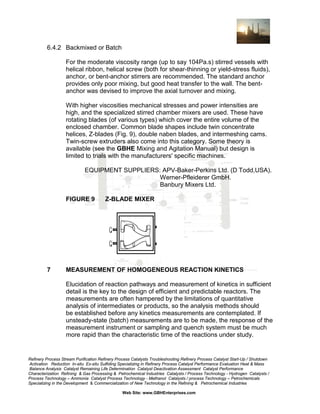
![Sometimes reactions of widely differing rate have to be accommodated
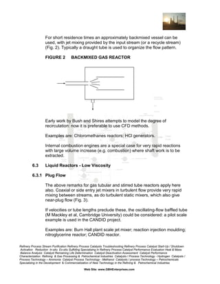
together and a combination of reactor types is used. This can also be
done for temperature effects, for example a backmixed zone with an
exothermic reaction can be placed before a plug flow reactor in order to
bring reactants up to temperature quickly [Ref. 1].
The models used to simulate the performance of the basic ideal reactor
types are described in 4.2. Non-ideal and more complicated cases are
dealt with in many textbooks, for example [Ref. 2], [3] and [4].
Residence time distribution in continuous reactors refers to mixedness in
the main flow direction. In plug flow, for any but first order reactions, the
degree of cross or radial mixedness is important: the extremes are often
referred to as premixed or segregated feeds; see GBHE-PEG-RXT-802.
Sometimes rapid radial mixers (e.g. turbulent jets) are used at the entry to
tubular plug flow reactors.
Obviously the theory can only be used for real reactors if the fluid
dynamics provide a reasonably close approach to one of the ideal
residence time distribution. Often this is not so, and more complex RTD
models are used, either:
(a)
Using networks of interlinked ideal reactors of appropriate size to
model a measured RTD (this descriptive method is touched on in
GBHE-PEG-RXT-802.
Or
(b)
Computing the flow patterns and reaction progress using
computational fluid dynamics (CFD) programs, which are basically
predictive since they use fine-detail fundamental calculations
without specific empirical input? GBHE-PEG-RXT-800 Series
Proprietary Tools for Reactor Modeling.
Refinery Process Stream Purification Refinery Process Catalysts Troubleshooting Refinery Process Catalyst Start-Up / Shutdown
Activation Reduction In-situ Ex-situ Sulfiding Specializing in Refinery Process Catalyst Performance Evaluation Heat & Mass
Balance Analysis Catalyst Remaining Life Determination Catalyst Deactivation Assessment Catalyst Performance
Characterization Refining & Gas Processing & Petrochemical Industries Catalysts / Process Technology - Hydrogen Catalysts /
Process Technology – Ammonia Catalyst Process Technology - Methanol Catalysts / process Technology – Petrochemicals
Specializing in the Development & Commercialization of New Technology in the Refining & Petrochemical Industries
Web Site: www.GBHEnterprises.com](https://image.slidesharecdn.com/homogeneousreactors-131017140219-phpapp02/85/Homogeneous-Reactors-7-320.jpg)
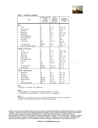
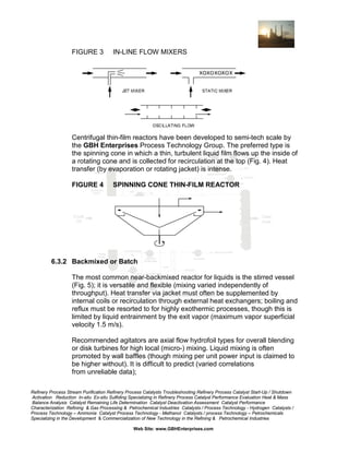
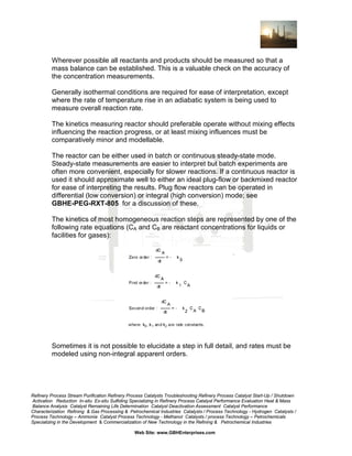
![4.2.3 Ideal Backmixed Reactor Model
This model gives a series of algebraic equations, e.g.:
The heat balance equation if the reactor is non-isothermal is:
4.3
Costing
The item cost of the reactor may be obtained from in-house engineers if it
is a vessel, tube, heat exchanger, etc., or from manufacturers if it is
proprietary device (such as a Sulzer mixer, Buss Loop Reactor, or high
viscosity mixer). This must be multiplied by factors (consult GBH
Enterprises, Engineering) for instrumentation, installation and design
charges to give the installed cost. Downstream equipment could be
specified approximately from short-cut design methods (see [Ref. 5], and
costed as above. Its cost may be substantially greater than that of the
reactor.
5
EQUIPMENT SELECTION SUMMARY
Table 1 lists a wide selection of designs, classified by Gas, Low Viscosity
Liquid, or High Viscosity Liquid, then according to flow pattern and heat
exchange system. Low Viscosity refers to liquids which can be practically
processed in turbulent flow; say Reynolds Number,
Re = ρDU / µ > 1000 or viscosity µ > 1 Pas (1000 cp).
Refinery Process Stream Purification Refinery Process Catalysts Troubleshooting Refinery Process Catalyst Start-Up / Shutdown
Activation Reduction In-situ Ex-situ Sulfiding Specializing in Refinery Process Catalyst Performance Evaluation Heat & Mass
Balance Analysis Catalyst Remaining Life Determination Catalyst Deactivation Assessment Catalyst Performance
Characterization Refining & Gas Processing & Petrochemical Industries Catalysts / Process Technology - Hydrogen Catalysts /
Process Technology – Ammonia Catalyst Process Technology - Methanol Catalysts / process Technology – Petrochemicals
Specializing in the Development & Commercialization of New Technology in the Refining & Petrochemical Industries
Web Site: www.GBHEnterprises.com](https://image.slidesharecdn.com/homogeneousreactors-131017140219-phpapp02/85/Homogeneous-Reactors-10-320.jpg)
![Complex interactions of species can be modeled with GBHE-PEG-RXT800 Series Proprietary Tools for Reactor Modeling.
Fitting of parameters to models is covered in GBHE-PEG-RXT-800 Series
Proprietary Tools for Reactor Modeling.
7.1
Gas Phase Reactions
Steady-state measurements are made using a small-diameter (<10 mm)
tubular reactor (a microreactor) installed in an appropriate constant
temperature environment. Integral or differential experiments can be
carried out according to ease of concentration measurement and
temperature control. as described in GBHE-PEG-RXT-805. Reactor
diameters of less than about 10mm are recommended to minimize the
effects of mass and heat transfer on the kinetic results. [Ref. 6] (Section
1.6) gives some guidance for handling complex reactions.
Batch methods available include temperature jump and pressure jump
methods, in which the well-mixed reactants are placed in a closed vessel
at non-reacting conditions, which are suddenly adjusted to the desired
reaction conditions. A suitable transient (pressure, temperature,
concentration) is measured and analyzed by fitting rate expressions to it.
Very rapid reactions can be studied in this way. See [Ref. 7].
7.2
Liquid Phase Reactions
Removal of diffusion limitations and mixing effects is more difficult than
with gas reactions.
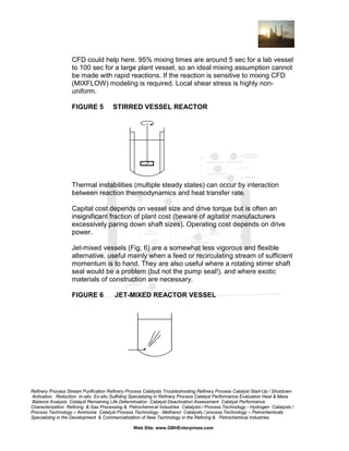
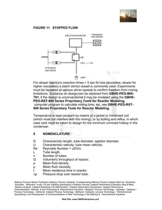
For steady-state isothermal work a tubular microreactor can be used but it
must be of very small diameter (Goddard and Deans recommend 0.2 - 0.5
mm [Ref. 13]) or run at high velocity to achieve adequate radial mixedness
to match a fully turbulent plant reactor. Radial mixing through the reactor,
and approach to plug flow, can be improved by using Static mixer (if a
sufficiently small one can be found). Initial mixing is often achieved using a
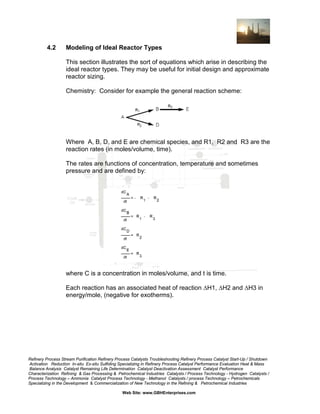
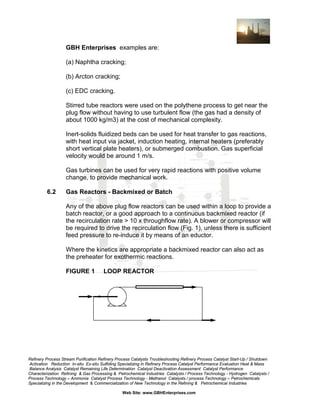
turbulent jet mixer of coaxial or T-jet design (Fig. 10) which for low
viscosity systems enable reaction times down to 10 msec to be studied.
See Reports [Refs 8], [9], [10] and [11]. Experiments should be repeated
at different velocities to check for absence of mixing effects.
Refinery Process Stream Purification Refinery Process Catalysts Troubleshooting Refinery Process Catalyst Start-Up / Shutdown
Activation Reduction In-situ Ex-situ Sulfiding Specializing in Refinery Process Catalyst Performance Evaluation Heat & Mass
Balance Analysis Catalyst Remaining Life Determination Catalyst Deactivation Assessment Catalyst Performance
Characterization Refining & Gas Processing & Petrochemical Industries Catalysts / Process Technology - Hydrogen Catalysts /
Process Technology – Ammonia Catalyst Process Technology - Methanol Catalysts / process Technology – Petrochemicals
Specializing in the Development & Commercialization of New Technology in the Refining & Petrochemical Industries
Web Site: www.GBHEnterprises.com](https://image.slidesharecdn.com/homogeneousreactors-131017140219-phpapp02/85/Homogeneous-Reactors-20-320.jpg)
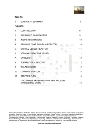
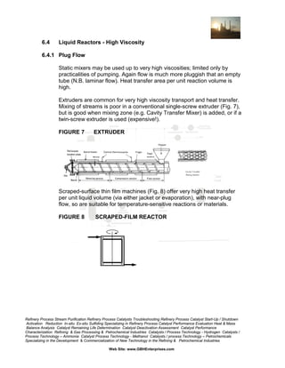
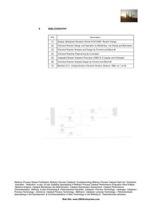
![FIGURE 10
CONTINUOUS FLOW
In the Integral form, extra information can be gathered by on-line
measurement (e.g. spectrophotometry, NMR, or small temperature
changes) or sampling (with rapid quench) at intervals along the tube.
For slower reactions a continuous stirred vessel reactor could be useful if
the backmixing is near ideal. Stirrer speed should be varied to check for
mixing effects.
A batch method is available for rapid aqueous reactions (reaction time 5
milliseconds) at <70°C and 1atm. This is the stopped flow technique (Fig.
11). Reactants flow through a small jet-mixed glass mixing cell, the flow is
suddenly stopped and the concentrations followed versus time by
spectrophotometry, or some other rapid response technique. The
equipment is available commercially; see Report [Ref. 12].
Refinery Process Stream Purification Refinery Process Catalysts Troubleshooting Refinery Process Catalyst Start-Up / Shutdown
Activation Reduction In-situ Ex-situ Sulfiding Specializing in Refinery Process Catalyst Performance Evaluation Heat & Mass
Balance Analysis Catalyst Remaining Life Determination Catalyst Deactivation Assessment Catalyst Performance
Characterization Refining & Gas Processing & Petrochemical Industries Catalysts / Process Technology - Hydrogen Catalysts /
Process Technology – Ammonia Catalyst Process Technology - Methanol Catalysts / process Technology – Petrochemicals
Specializing in the Development & Commercialization of New Technology in the Refining & Petrochemical Industries
Web Site: www.GBHEnterprises.com](https://image.slidesharecdn.com/homogeneousreactors-131017140219-phpapp02/85/Homogeneous-Reactors-21-320.jpg)


The document is a process engineering guide from GBH Enterprises that discusses the design of homogeneous reactors. It provides definitions and outlines the key design steps, including determining reaction kinetics, selecting the ideal reactor type based on required residence time and flow pattern, and modeling different reactor configurations. Examples of equipment for gas and liquid phase reactors are also included to aid in the initial selection process.


