Downloaded 132 times

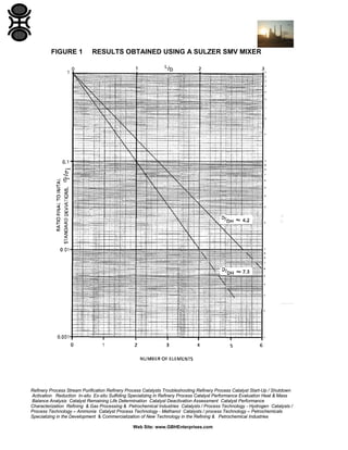
![Static mixers can achieve good mixing in less than five pipe diameters regardless
of the density difference. Figure 1 shows the results obtained using a Sulzer
SMV mixer. Unless the densities are similar and the flow rates constant, a
minimum operating velocity, UG, is recommended. For the Sulzer SMV mixer,
this is obtained if the modified Froude number exceeds 20 [Ref 1 : Germain et
al., 1982]:
. The values of f and DH are obtained from the manufacturers' data;
Refinery Process Stream Purification Refinery Process Catalysts Troubleshooting Refinery Process Catalyst Start-Up / Shutdown
Activation Reduction In-situ Ex-situ Sulfiding Specializing in Refinery Process Catalyst Performance Evaluation Heat & Mass
Balance Analysis Catalyst Remaining Life Determination Catalyst Deactivation Assessment Catalyst Performance
Characterization Refining & Gas Processing & Petrochemical Industries Catalysts / Process Technology - Hydrogen Catalysts /
Process Technology – Ammonia Catalyst Process Technology - Methanol Catalysts / process Technology – Petrochemicals
Specializing in the Development & Commercialization of New Technology in the Refining & Petrochemical Industries
Web Site: www.GBHEnterprises.com](https://image.slidesharecdn.com/gasmixing-131017103934-phpapp02/85/Gas-Mixing-5-320.jpg)
![6
BIBLIOGRAPHY
Reference
Authors, Title and Source
[1]
Germain, E & Wetter, R. Mélange Statique de gaz, Informations
Chimie No. 232. Dec 1982, p 135 (referred to in Clause 4).
Refinery Process Stream Purification Refinery Process Catalysts Troubleshooting Refinery Process Catalyst Start-Up / Shutdown
Activation Reduction In-situ Ex-situ Sulfiding Specializing in Refinery Process Catalyst Performance Evaluation Heat & Mass
Balance Analysis Catalyst Remaining Life Determination Catalyst Deactivation Assessment Catalyst Performance
Characterization Refining & Gas Processing & Petrochemical Industries Catalysts / Process Technology - Hydrogen Catalysts /
Process Technology – Ammonia Catalyst Process Technology - Methanol Catalysts / process Technology – Petrochemicals
Specializing in the Development & Commercialization of New Technology in the Refining & Petrochemical Industries
Web Site: www.GBHEnterprises.com](https://image.slidesharecdn.com/gasmixing-131017103934-phpapp02/85/Gas-Mixing-11-320.jpg)


The document is a process engineering guide from GBH Enterprises outlining gas mixing techniques and recommendations for refining and petrochemical applications. It covers various aspects of gas mixing, including design procedures for different mixer types and specific contexts such as pre-reaction zones and recirculation flows. The guide serves as a technical resource for process engineers, emphasizing the importance of evaluating gas mixing methodologies to enhance performance and reliability in industrial applications.


