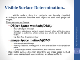
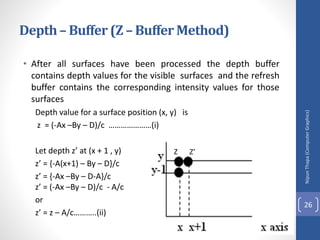
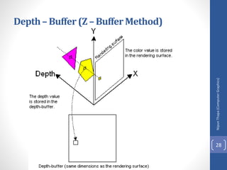
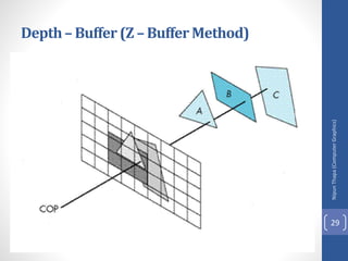
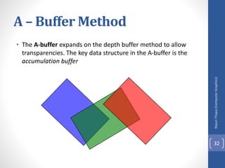
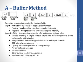
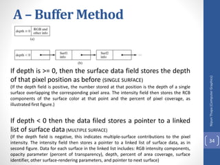
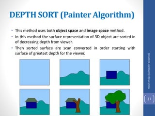
Visible Surface
Determination
Unit 4
Nipun
Thapa
(Computer
Graphics)
1
Visible Surface Detection (Hidden
Surface Removal) Method
It is the process of identifying those parts of a scene that
are visible from a chosen viewing position. There are numerous
algorithms for efficient identification of visible objects for
different types of applications. These various algorithms are
referred to as visible-surface detection methods. Sometimes
these methods are also referred to as hidden-surface
elimination methods.
• To identify those parts of a scene that are visible from a
chosen viewing position (visible-surface detection methods).
• Surfaces which are obscured by other opaque (solid) surfaces
along the line of sight are invisible to the viewer so can be
eliminated (hidden-surface elimination methods).
Nipun
Thapa
(Computer
Graphics)
2
Visible Surface Determination..
Visible surface detection methods are broadly classified
according to whether they deal with objects or with their projected
images.
These two approaches are
• Object-Space methods(OSM):
• Deal with object definition
• Compares objects and parts of objects to each other within the scene
definition to determine which surface as a whole we should label as
visible.
• E.g. Back-face detection method
• Image-Space methods(ISM):
• Deal with projected image
• Visibility is decided point by point at each pixel position on the projection
plane.
• E.g. Depth-buffer method, Scan-line method, Area-subdivision method
• Most visible surface detection algorithm use image-space-method
but in some cases object space methods are also used for it.
Nipun
Thapa
(Computer
Graphics)
3
Visible Surface Determination..
•List Priority Algorithms
• This is a hybrid model that combines both object and image
precision operations. Here, depth comparison & object splitting
are done with object precision and scan conversion (which relies
on ability of graphics device to overwrite pixels of previously
drawn objects) is done with image precision.
• E.g. Depth-Shorting method, BSP-tree method
Nipun
Thapa
(Computer
Graphics)
4
Nipun
Thapa
(Computer
Graphics)
5
Visible Surface Determination
Nipun
Thapa
(Computer
Graphics)
6
Visible Surface Determination
Nipun
Thapa
(Computer
Graphics)
7
Visible Surface Determination
Object-Space methods
Nipun
Thapa
(Computer
Graphics)
8
Object-Space methods
Nipun
Thapa
(Computer
Graphics)
9
Image Space Methods
Nipun
Thapa
(Computer
Graphics)
10
Image Space Methods
Nipun
Thapa
(Computer
Graphics)
11
Nipun
Thapa
(Computer
Graphics)
12
Back – Face Detection Method
• A fast and simple object-space method for identifying the back faces
of a polyhedron.
• It is based on the performing inside-outside test.
TWO METHODS:
First Method:
• A point (x, y, z) is "inside" a polygon surface with plane parameters
A, B, C, and D if Ax+By+Cz+D < 0 (from plane equation).
• When an inside point is along the line of sight to the surface, the
polygon must be a back face.
• In eq. Ax+By+Cz+D=0
if A,B,C remain constant , then varying value of D result in a whole
family of parallel plane
if D>0, plane is behind the origin (Away from observer)
if D<0 , plane is in front of origin (toward the observer)
Nipun
Thapa
(Computer
Graphics)
13
Second Way
• Let N be normal vector to a polygon surface, which has
Cartesian components (A, B, C). In general, if V is a vector in
the viewing direction from the eye (or "camera") position,
then this polygon is a back face
if V.N>0.
Nipun
Thapa
(Computer
Graphics)
14
Back – Face Detection Method
Nipun
Thapa
(Computer
Graphics)
15
Back – Face Detection Method
Nipun
Thapa
(Computer
Graphics)
16
Back – Face Detection Method
A view vector V is constructed from any point on the surface to the
viewpoint, the dot product of this vector and the normal N, indicates visible faces
as follows:
Case-I: (FRONT FACE)
If V.N < 0 the face is visible else face is hidden
Case-II: (BACK FACE)
If V.N > 0 the face is visible else face is hidden
Case-III:
For other objects, such as the concave polyhedron in Fig., more
tests need to be carried out to determine whether there are additional
faces that are totally or partly obscured by other faces.
Nipun
Thapa
(Computer
Graphics)
17
Numerical
Nipun
Thapa
(Computer
Graphics)
18
# Find the visibility for the surface AED in rectangular pyramid where an
observer is at P (5, 5, 5).
Solution
Here,
AE = (0-1)i + (1-0)j + (0-0)k = -i + j
AD= (0-1)i + (1-0)j + (1-0)k =-i + k
Step-1:
Normal vector N for AED
Thus, N = AE x AD =
Case-II
Step-2: If observer at P(5, 5, 5) so we can construct the view vector V from
surface to view point A(1, 0, 0) as:
V = AP = (5-1)i + (5-0)j + (5-0)k = 4i + 5j + 5k
Step-3: To find the visibility of the object, we use dot product of view vector V
and normal vector N as:
V.N = (4i + 5j + 5k).(i + j + k) = 4+5+5 = 14> 0
This shows that the surface is visible for the observer.
Case-I
Step-2: If observer at P(5, 5, 5) so we can construct the view
vector
V from surface to view point A(1, 0, 0) as:
V = PA = (1-5)i + (0-5)j + (0-5)k = -4i - 5j - 5k
Step-3: To find the visibility of the object, we use dot product of
view vector V and normal vector N
as:
V.N = (-4i - 5j - 5k).(i + j + k) = -4-5-5 = -14< 0
This shows that the surface is visible for the observer.
Nipun
Thapa
(Computer
Graphics)
19
• # Find the visibility for the surface AED in rectangular pyramid
where an observer is at P (0,0.5, 0).
Nipun
Thapa
(Computer
Graphics)
20
Depth– Buffer (Z – Buffer Method)
• A commonly used image-space approach to detecting visible
surfaces is the depth-buffer method, which compares surface
depths at each pixel position on the projection plane.
• Also called z-buffer method since depth usually measured
along z-axis. This approach compares surface depths at each
pixel position on the projection plane.
• Each surface of a scene is processed separately, one point at a
time across the surface. And each (x, y, z) position on a
polygon surface corresponds to the projection point (x, y) on
the view plane.
Nipun
Thapa
(Computer
Graphics)
21
This method requires two buffers:
• A z-buffer or depth buffer: Stores depth values for each pixel
position (x, y).
• Frame buffer (Refresh buffer): Stores the surface-intensity
values or color values for each pixel position.
• As surfaces are processed, the image buffer is used to store
the color values of each pixel position and the z-buffer is used
to store the depth values for each (x, y) position.
Nipun
Thapa
(Computer
Graphics)
22
Depth– Buffer (Z – Buffer Method)
Nipun
Thapa
(Computer
Graphics)
23
Depth– Buffer (Z – Buffer Method)
Initially, all positions in the depth buffer are set to 0
(minimum depth), and the refresh buffer is initialized to the
background intensity. Each surface listed in the polygon tables is
then processed, one scan line at a time, calculating the depth (z-
value) at each (x, y) pixel position. The calculated depth is
compared to the value previously stored in the depth buffer at
that position. If the calculated depth is greater than the value
stored in the depth buffer, the new depth value is stored, and
the surface intensity at that position is determined and placed in
the same xy location in the refresh buffer.
A drawback of the depth-buffer method is that it can only
find one visible surface for opaque surfaces and cannot
accumulate intensity values for transparent surfaces.
Nipun
Thapa
(Computer
Graphics)
24
Algorithm:
1. Initialize both, depth buffer and refresh buffer for all buffer positions (x, y),
depth(x, y) = 0
refresh(x, y) = Ibackground,
(where Ibackground is the value for the background intensity.)
2. Process each polygon surface in a scene one at a time,
( Each surface listed in the polygon tables is then processed, one scan line at a time, calculating the depth (z-value) at each
(x, y) pixel position.)
2.1. Calculate the depth z for each (x, y) position on the polygon.
(The calculated depth is compared to the value previously stored in the depth buffer at that position.)
2.2. If Z > depth(x, y), then set
depth(x, y)=z (If the calculated depth is greater than the value stored in the depth buffer, the new depth value is stored,)
refresh(x, y)= Isurf(x, y),
(where Isurf(x, y) is the intensity value for the surface at pixel position (x, y). )
3. After all pixels and surfaces are compared, draw object using X,Y,Z from depth
and intensity refresh buffer.
Nipun
Thapa
(Computer
Graphics)
25
Depth– Buffer (Z – Buffer Method)
• After all surfaces have been processed the depth buffer
contains depth values for the visible surfaces and the refresh
buffer contains the corresponding intensity values for those
surfaces
Depth value for a surface position (x, y) is
z = (-Ax –By – D)/c …………………(i)
Let depth z’ at (x + 1 , y)
z’ = {-A(x+1) – By – D}/c
z’ = {-Ax –By – D-A}/c
z’ = (-Ax –By – D)/c - A/c
or
z’ = z – A/c………..(ii)
Nipun
Thapa
(Computer
Graphics)
26
Depth– Buffer (Z – Buffer Method)
Z Z’
Nipun
Thapa
(Computer
Graphics)
27
Depth– Buffer (Z – Buffer Method)
Nipun
Thapa
(Computer
Graphics)
28
Depth– Buffer (Z – Buffer Method)
Nipun
Thapa
(Computer
Graphics)
29
Depth– Buffer (Z – Buffer Method)
Class Work
Q.N.1> Write a procedure to fill the interior of a given ellipse
with a specified pattern. (2070 TU)
.
Q.N.2> What do you mean by line clipping? Explain the
procedures for line clipping. (2070 TU)
Nipun
Thapa
(Computer
Graphics)
30
A – Buffer Method
• The A-buffer (anti-aliased, area-averaged, accumulation
buffer) is an extension of the ideas in the depth-buffer
method (other end of the alphabet from "z-buffer").
• A drawback of the depth-buffer method is that it deals only
with opaque(Solid) surfaces and cannot accumulate intensity
values for more than one transparent surfaces.
• The A-buffer method is an extension of the depth-buffer
method.
• The A-buffer is incorporated into the REYES ("Renders
Everything You Ever Saw") 3-D rendering system.
• The A-buffer method calculates the surface intensity for
multiple surfaces at each pixel position, and object edges can
be ant aliased.
Nipun
Thapa
(Computer
Graphics)
31
A – Buffer Method
• The A-buffer expands on the depth buffer method to allow
transparencies. The key data structure in the A-buffer is the
accumulation buffer
Nipun
Thapa
(Computer
Graphics)
32
A – Buffer Method
Each pixel position in the A-Buffer has two fields
Depth Field : stores a positive or negative real number
• Positive : single surface contributes to pixel intensity
• Negative : multiple surfaces contribute to pixel intensity
Intensity Field : stores surface-intensity information or a pointer value
• Surface intensity if single surface stores the RGB components of the
surface color at that point
• and percent of pixel coverage Pointer value if multiple surfaces
• RGB intensity components
• Opacity parameter(per cent of transparency)
• Per cent of area coverage
• Surface identifier
• Other surface rendering parameters
• Pointer to next surface (Link List)
Nipun
Thapa
(Computer
Graphics)
33
A – Buffer Method
If depth is >= 0, then the surface data field stores the depth
of that pixel position as before (SINGLE SURFACE)
(If the depth field is positive, the number stored at that position is the depth of a single
surface overlapping the corresponding pixel area. The intensity field then stores the RCB
components of the surface color at that point and the percent of pixel coverage, as
illustrated first figure.)
If depth < 0 then the data filed stores a pointer to a linked
list of surface data(MULTIPLE SURFACE)
(If the depth field is negative, this indicates multiple-surface contributions to the pixel
intensity. The intensity field then stores a pointer to a linked list of surface data, as in
second figure. Data for each surface in the linked list includes: RGB intensity components,
opacity parameter (percent of transparency), depth, percent of area coverage, surface
identifier, other surface-rendering parameters, and pointer to next surface)
Nipun
Thapa
(Computer
Graphics)
34
A – Buffer Method
• The A-buffer can be constructed using methods similar to
those in the depth-buffer algorithm. Scan lines are processed
to determine surface overlaps of pixels across the individual
scan lines. Surfaces are subdivided into a polygon mesh and
clipped against the pixel boundaries. Using the opacity factors
and percent of surface overlaps, we can calculate the intensity
of each pixel as an average of the contributions from the over
lapping surfaces.
Nipun
Thapa
(Computer
Graphics)
35
Class Work
Q.N.1 > Explain with algorithm of generating curves. (TU 2071)
Q.N.2 > Set up a procedure for establishing polygon tables for
any input set of data defining an object. (TU 2071)
Q.N.3 > Explain the window to view port transformation with its
applications. (TU 2071/2070)
Q.N.4 > Write a procedure to perform a two-point perspective
projection of an object. (TU 2070)
Nipun
Thapa
(Computer
Graphics)
36
• This method uses both object space and image space method.
• In this method the surface representation of 3D object are sorted in
of decreasing depth from viewer.
• Then sorted surface are scan converted in order starting with
surface of greatest depth for the viewer.
DEPTH SORT (Painter Algorithm)
Nipun
Thapa
(Computer
Graphics)
37
The conceptual steps that performed
in depth-sort algorithm are
1. Sort all polygon surface according to the smallest
(farthest) Z co-ordinate of each.
2. Resolve any ambiguity(doubt) this may cause when the
polygons Z extents overlap, splitting polygons if
necessary.
3. Scan convert each polygon in ascending order of
smaller Z-co-ordinate i.e. farthest surface first (back to
front)
Nipun
Thapa
(Computer
Graphics)
38
• In this method, the newly displayed surface is partly or
completely obscure the previously displayed surface.
Essentially, we are sorting the surface into priority order
such that surface with lower priority (lower z, far objects)
can be obscured by those with higher priority (high z-
value).
DEPTH SORT (Painter Algorithm)
Nipun
Thapa
(Computer
Graphics)
39
• This algorithm is also called "Painter's Algorithm" as it
simulates how a painter typically produces his painting
by starting with the background and then progressively
adding new (nearer) objects to the canvas.
• Thus, each layer of paint covers up the previous layer.
• Similarly, we first sort surfaces according to their distance
from the view plane. The intensity values for the farthest
surface are then entered into the refresh buffer. Taking
each succeeding surface in turn (in decreasing depth
order), we "paint" the surface intensities onto the frame
buffer over the intensities of the previously processed
surfaces.
DEPTH SORT (Painter Algorithm)
Nipun
Thapa
(Computer
Graphics)
40
Nipun
Thapa
(Computer
Graphics)
41
DEPTH SORT (Painter Algorithm)
Problem
Problem
• One of the major problem in this algorithm is intersecting polygon
surfaces. As shown in fig. below.
o Different polygons may have same depth.
o The nearest polygon could also be farthest.
We cannot use simple depth-sorting to remove the hidden-surfaces in the images.
DEPTH SORT (Painter Algorithm)
Nipun
Thapa
(Computer
Graphics)
42
Solution
• For intersecting polygons, we can split one polygon into
two or more polygons which can then be painted from
back to front. This needs more time to compute
intersection between polygons. So it becomes complex
algorithm for such surface existence.
DEPTH SORT (Painter Algorithm)
Nipun
Thapa
(Computer
Graphics)
43
DEPTH SORT (Painter Algorithm)
Nipun
Thapa
(Computer
Graphics)
44
Scan-Line Method
• This image-space method for removing hidden surfaces is an
extension of the scan-line algorithm for filling polygon
interiors where, we deal with multiple surfaces rather than
one.
• Each scan line is processed with calculating the depth for
nearest view for determining the visible surface of intersecting
polygon. When the visible surface has been determined, the
intensity value for that position is entered into the refresh
buffer.
Nipun
Thapa
(Computer
Graphics)
45
Scan-Line Method
• To facilitate the search for surfaces crossing a given scan line,
we can set up an active list of edges from information in the
edge table that contain only edges that cross the current scan
line, sorted in order of increasing x.
• In addition, we define a flag for each surface that is set on or
off to indicate whether a position along a scan line is inside or
outside of the surface. Scan lines are processed from left to
right.
• At the leftmost boundary of a surface, the surface flag is
turned on; and at the rightmost boundary, it is turned off.
Nipun
Thapa
(Computer
Graphics)
46
Scan-Line Method
DATA STRUCTURE
• A. Edge table containing
• Coordinate endpoints for each line in a scene
• Inverse slope of each line
• Pointers into polygon table to identify the surfaces bounded by each line
• B. Surface table containing
• Coefficients of the plane equation for each surface
• Intensity information for each surface
• Pointers to edge table
• C. Active Edge List
• To keep a trace of which edges are intersected by the given scan line
Note :
• The edges are sorted in order of increasing x
• Define flags for each surface to indicate whether a position is inside or
outside the surface
Nipun
Thapa
(Computer
Graphics)
47
I. Initialize the necessary data structure
1. Edge table containing end point coordinates, inverse slope and
polygon pointer.
2. Surface table containing plane coefficients and surface intensity
3. Active Edge List
4. Flag for each surface
II. For each scan line repeat
1. update active edge list
2. determine point of intersection and set surface on or off.
3. If flag is on, store its value in the refresh buffer
4. If more than one surface is on, do depth sorting and store the
intensity of surface nearest to view plane in the refresh buffer
Nipun
Thapa
(Computer
Graphics)
48
Scan-Line Method
• For scan line 1
• The active edge list contains edges AB,BC,EH, FG
• Between edges AB and BC, only flags for s1 == on and
between edges EH and FG, only flags for s2==on
• no depth calculation needed and corresponding surface
intensities are entered in refresh buffer
• For scan line 2
• The active edge list contains edges AD,EH,BC and FG
• Between edges AD and EH, only the flag for surface s1 == on
• Between edges EH and BC flags for both surfaces == on
• Depth calculation (using plane coefficients) is needed.
• In this example ,say s2 is nearer to the view plane than s1, so
intensities for surface s2 are loaded into the refresh buffer
until boundary BC is encountered
• Between edges BC and FG flag for s1==off and flag for s2 ==
on
• Intensities for s2 are loaded on refresh buffer
• For scan line 3
• Same coherent property as scan line 2 as noticed from active
list, so no depth
Nipun
Thapa
(Computer
Graphics)
49
Scan-Line Method
Problem:
Dealing with cut through surfaces and
cyclic overlap is problematic when
used coherent properties
• Solution: Divide the surface to
eliminate the overlap or cut through
Nipun
Thapa
(Computer
Graphics)
50
Scan-Line Method
Class Work
Q.N.1> What do you mean by homogeneous coordinates? Rotate a triangle
A(5,6), B(6,2) and C(4,1) by 45 degree about an arbitrary pivot point (3,3).
(TU 2072)
Q.N.2> Given a clipping window P(0,0), Q(30,20), S(0,20) use the Cohen
Sutherland algorithm to determine the visible portion of the line A(10,30)
and B(40,0). (TU 2072)
Q.N.3> Explain polygon clipping in detail. By using the sutherland-
Hodgemen Polygon clipping algorithm clip the following polygon. (TU 2072)
Nipun
Thapa
(Computer
Graphics)
51
Illumination models
and surface rendering
methods
Nipun
Thapa
(Computer
Graphics)
52
Illumination and surface rendering model
• Once visible surface has been identified by hidden surface
algorithm, a shading model is used to compute the intensities and
color to display for the surface. For realistic displaying of 3d scene it
is necessary to calculate appropriate color or intensity for that
scene.
• Illumination model or a lighting model is the model for calculating
light intensity at a single surface point. Sometimes also referred to
as a shading model.
• An illumination model is also called lighting model and some times
called as a shading model which is used to calculate the intensity of
light that we should see at a given point on the surface of a object.
• A surface-rendering algorithm uses the intensity calculations from
an illumination model.
Components of Illumination model
• Light Sources: type , color, and direction of the light source
• Surface Properties : réflectance, opaque/transparent, shiny/dull.
Nipun
Thapa
(Computer
Graphics)
53
Illumination And Rendering
• An illumination model in computer graphics
• also called a lighting model or a shading model
• used to calculate the color of an illuminated position on the
surface of an object
• Approximations of the physical laws
• A surface-rendering method determine the pixel colors for all
projected positions in a scene
Nipun
Thapa
(Computer
Graphics)
54
Light Source
• Object that radiates energy are called light sources, such as
sun, lamp, bulb, fluorescent tube etc.
• Sometimes light sources are referred as light emitting object
and light reflectors. Generally light source is used to mean an
object that is emitting radiant energy e.g. Sun.
• Total Reflected Light = Contribution from light sources +
contribution from reflecting surfaces
Nipun
Thapa
(Computer
Graphics)
55
Light Source..
Nipun
Thapa
(Computer
Graphics)
56
Point Source:
Point source is the simplest light emitter e.g. light bulb.
When light source model is a reasonable approximation for sources
whose dimensions are small compared to the size of objects in a
scene.
Distributed Light Source:
area of source is not small compared to the surfaces in the
scene e.g. Fluorescent lamp
Reflectionof light:
When light is incident on opaque surface part of it is
reflected and part of it is absorbed.
∴ I = A+R
• The amount of incident light reflected by a surface depends
on the type of material. Shining material reflects more
incident light and dull surface absorbs more of the incident
light. For transparent surfaces, some of the incident light will
be reflected and some will be transmitted through the
material.
Nipun
Thapa
(Computer
Graphics)
57
Distributedlightsource
• When light is incident on an opaque surface part of it is
reflected and part of it is absorbed.
• Surface that are rough or grainy, tend to scatter the reflected
light in all direction which is called diffuse reflection.
• When light sources create highlights, or bright spots, called
specular reflection
Nipun
Thapa
(Computer
Graphics)
58
Light Source..
• Point source: Simplest model for a light emitter like tungsten
filament bulb
• Distributed light source: The area of the source is not small
compared to the surfaces in the scene like fluorescent light on
any object in a room
• Diffuse reflection: Scatter reflected light in all direction by
rough or grainy surfaces.
• Specular-reflection: highlights or bright spots created by light
source, particularly on shiny surfaces than on dull surfaces.
Nipun
Thapa
(Computer
Graphics)
59
Illumination models:
Illumination models are used to calculate light intensities
that we should see at a given point on the surface of an object.
Lighting calculations are based on the optical properties of
surfaces, the background lighting conditions and the light source
specifications. All light sources are considered to be point
sources, specified with a co-ordinate position and an intensity
value (color). Some illumination models are:
1. Ambient Light
2. Diffuse Reflection
3. Specular Reflection and pong model
Nipun
Thapa
(Computer
Graphics)
60
Someusefulconcept
Nipun
Thapa
(Computer
Graphics)
61
1. Ambient light:
• This is a simplest illumination model
• We can think of this model, which has no external light
source-self-luminous objects. A surface that is not exposed
directly to light source still will be visible if nearby objects are
illuminated.
• The combination of light reflections form various surfaces to
produce a uniform illumination is called ambient light or
background light.
• Also called background light
• Ambient light means the light that is already present in a
scene, before any additional lighting is added. It usually refers
to natural light, either outdoors or coming through windows
etc. It can also mean artificial lights such as normal room
lights.
Nipun
Thapa
(Computer
Graphics)
62
Nipun
Thapa
(Computer
Graphics)
63
1. Ambient light:
1. Ambient light …
• Multiple reflection of nearby (light-reflecting) objects yields a
uniform illumination
• A form of diffuse reflection independent of the viewing
direction and the spatial orientation of a surface
• Ambient light has no spatial or directional characteristics and
amount on each object is a constant for all surfaces and all
directions. In this model, illumination can be expressed by an
illumination equation in variables associated with the point on
the object being shaded. The equation expressing this simple
model is
I=Ka
Where I is the resulting intensity and Ka is the object’s intrinsic
intensity.
Nipun
Thapa
(Computer
Graphics)
64
1. Ambient light …
• If we assume that ambient light impinges equally on all
surface from all direction, then
I = Ia Ka
Where Ia is intensity of ambient light. The amount of light
reflected from an object's surface is determined by Ka , the
ambient-reflection coefficient. Ka ranges from 0 to 1.
Nipun
Thapa
(Computer
Graphics)
65
2. Diffuse Reflection
• Objects illuminated by ambient light are uniformly illuminated
across their surfaces even though light are more or less bright
in direct proportion of ambient intensity.
• Surfaces are rough
• Incident light is scattered with equal intensity in all directions
• Surfaces appear equally bright from all direction.
• Such surfaces are called ideal diffuse reflectors (also referred
to as Lambertian reflectors)
Nipun
Thapa
(Computer
Graphics)
66
2. Diffuse Reflection…
• Illuminating object by a point light source, whose rays
enumerate uniformly in all directions from a single point. The
object's brightness varies form one part to another, depending
on the direction of and distance to the light source.
• Color of an object is determined by the color of the diffuse
reflection of the incident light.
• If any object surface is red then there is a diffuse reflection for
red component of light and all other components are
absorbed by the surface.
Nipun
Thapa
(Computer
Graphics)
67
2. Diffuse Reflection…
The diffuse-reflection coefficient, or diffuse reflectivity,
kd (varying from 0 to 1) define the fractional amount of the
incident light that is diffusely reflected.
The parameter kd (actually function of surface
color)depends on the reflecting properties of material so for
highly reflective surfaces, the kd nearly equal to 1.
If a surface is exposed only to ambient light, we can
express the intensity of the diffuse reflection at any point on the
surface as:
IambDiff = kd . Ia, (where Ia = intensity of ambient light)
Nipun
Thapa
(Computer
Graphics)
68
2. Diffuse Reflection…
If N is the unit normal vector to a surface and L is the unit
direction vector to the point light source from a position on the
surface then cos θ = N.L ( Lambertian Cosine Law) and the diffuse
reflection equation for single point source illumination is:
Il, diff = kd . Il cos θ = kd Il (N.L)
Nipun
Thapa
(Computer
Graphics)
69
2. Diffuse Reflection…
We can combine the ambient and point source intensity
calculations to obtain an expression for the total diffuse
reflection. Thus, we can write the total diffuse reflection
equation as:
IDiff = kd . Ia + kd Il (N.L)
Nipun
Thapa
(Computer
Graphics)
70
Lambert’sCosineLaw:
The intensity of diffuse reflection due to ambient light is;
Iadiff = kaIa
The radiant energy from any small surface dA in any direction relative
to surface normal is proportional to cos 𝜃. That is, brightness depends only on
the angle θ between the light direction L and the surface normal N.
∴ Light intensity α cos 𝜃.
Nipun
Thapa
(Computer
Graphics)
71
Fig: Angle of incidence θ between the
unit light-source direction vector L and
the unit surface normal
If Il is the intensity of the point light
source and kd is the diffuse reflection coefficient,
then the diffuse reflection for single point-
source can be written as;
Ιpdiff = kdIl cosθ
Ιpdiff = kdΙl (Ν ∙L)
∴ Total diffuse reflection (Idiff) = Diff ( due to ambient light)+Diff. due to pt.source.
Idiff = Iadiff + Ιpdiff
Idiff = kaIa + kdΙl (Ν ∙L)
Nipun
Thapa
(Computer
Graphics)
72
Class Work
Q.N.1. > Reflect the line A (1,1) and B(3,3) at y=x+3.
Q.N.2>Digitize the line A (15, 10) and B (20, 25) using BLA.
Q.N.3> Digitize the line A (5, 10) and B (20, 15) using BLA
Nipun
Thapa
(Computer
Graphics)
73
3. Specular reflection and pong model.
• When we look at an illuminated shiny surface, such as
polished metal, a person's forehead, we see a highlight or
bright spot, at certain viewing direction. Such phenomenon is
called specular reflection.
• It is the result of total or near total reflection of the incident
light in a concentrated region around the " specular reflection
angle = angle of incidence".
• Perfect reflector (mirror) reflects all lights to the direction
where angle of reflection is identical to the angle of incidence
• It accounts for the highlight
Nipun
Thapa
(Computer
Graphics)
74
Nipun
Thapa
(Computer
Graphics)
75
Let SR angle = angle of incidence as in
figure.
N - unit vector normal to surface at
incidence point
R - unit vector in the direction of
ideal specular reflection.
L - unit vector directed to words
point light source.
V - unit vector pointing to the
viewer from surface.
Ø− the viewing angle relative to the
specular reflection direction.
Nipun
Thapa
(Computer
Graphics)
76
3. Specularreflectionand phong model.
• For ideal reflector (perfect mirror), incident light is reflected only in
the specular reflection direction.
V & R concide (Ø = 0)
• Shiny surface have narrow Ø and dull surface wider Ø .
• An empirical model for calculating specular-reflection range
developed by Phong Bui Tuong-called Phong specular reflection
model (or simply Phong model), sets the intensity of specular
reflection proportional to cosns Ø 0 to 900 .
• Specular reflection parameter ns is determined by type of surface
• Intensity of specular reflection depends upon material properties of
the surface and ɵ . Other factors such as the polarization and color
of the incident light.
• - For monochromatic specular intensity variations can approximated
by SR coefficient w(ɵ)
Nipun
Thapa
(Computer
Graphics)
77
3. Specularreflectionand phong model.
Nipun
Thapa
(Computer
Graphics)
78
3. Specularreflectionand phong model.
• Fresnal's law of reflection describe specular reflection
intensity with and using w(ɵ ) , Phong specular reflection
model as
I spec = w(ɵ) Il cosns Ø
• Where Il is intensity of light source. is viewing angle relative to SR
direction R. For a glass, we can replace w(ɵ) with constant Ks
specular reflection coefficient.
Nipun
Thapa
(Computer
Graphics)
79
3. Specularreflectionand phong model.
Nipun
Thapa
(Computer
Graphics)
80
3. Specularreflectionand phong model.
Nipun
Thapa
(Computer
Graphics)
81
Nipun
Thapa
(Computer
Graphics)
82
Nipun
Thapa
(Computer
Graphics)
83
Class Work
Q.N.1> What is Bresenham’s line algorithm? How can you draw
line using this algorithm?
Q.N.2>Write mid-point Circle algorithm with description ?
Nipun
Thapa
(Computer
Graphics)
84
Intensity Attenuation
As radiant energy from a point light source travels
through space, its amplitude is attenuated by the factor l/d2,
where d is the distance that the light has traveled.
This means that a surface close to the light source (small
d) receives higher incident intensity from the source than a
distant surface (large d).
Therefore to produce realistic lighting effects,
illumination model should take intensity attenuation into
account. Otherwise we are likely to illuminate all surfaces with
same intensity.
• For a point light source attenuation factor is 1/d2.
• And for a distributed light source attenuation factor is given by
inverse quadratic attenuation function, f(d) =1/(a0 + a1d+a2d2).
Nipun
Thapa
(Computer
Graphics)
85
Transparency
Nipun
Thapa
(Computer
Graphics)
86
Transparency
Nipun
Thapa
(Computer
Graphics)
87
Shadow
Nipun
Thapa
(Computer
Graphics)
88
• Shadow can help to create realism. Without it, a cup, e.g., on a
table may look as if the cup is floating in the air above the
table.
• By applying hidden-surface methods with pretending that the
position of a light source is the viewing position, we can find
which surface sections cannot be "seen" from the light source
=> shadow areas.
• We usually display shadow areas with ambient-light intensity
only.
Nipun
Thapa
(Computer
Graphics)
89
Shadow
Class Work
• Q.N.1.> Model the Bezier curve. Explain the importance of
Bezier curve in graphical modeling. (TU 2070)
• Q.N.2>What is solid modeling? Explain the basic procedure for
solid modeling. (TU 2070)
• Q.N.3>if the total number of intensities achievable out of a
single pixel on the screen is 1024 and the total resolution of
the screen is 1024 X 800 , what will be the required size of
frame buffer in this case for the display purpose ?
• Q.N.4>Consider three different raster system with resolution
640 by 400, 1280 by 1024 and 2560 by 2048. what size frame
buffer (in byte) is needed for each of the system to store 12
bits per pixel ? How much storage is required for each system
if 24 bit per pixel are to be stored.
Nipun
Thapa
(Computer
Graphics)
90
Polygon Rendering Method
(Surface Shading Method)
• Objects usually polygon-mesh approximation
• Illumination model is applied to fill the interior of polygons
• Curved surfaces are approximated with polygon meshes
• But polyhedra that are not curved surfaces are also modeled with polygon
meshes
• Two ways of polygon surface rendering:
1. Single intensity for all points in a polygon
2. Interpolation of intensities for each point in a polygon
• Methods:
1. Constant Intensity Shading
2. Gouraud Shading
3. Phong Shading
Nipun
Thapa
(Computer
Graphics)
91
1. Constant Intensity Shading
Nipun
Thapa
(Computer
Graphics)
92
2. Gouraud Shading
Nipun
Thapa
(Computer
Graphics)
93
2. Gouraud Shading…..
Nipun
Thapa
(Computer
Graphics)
94
• For Gouraud shading, the intensity at
point 4 is linearly interpolated from the
intensities at vertices 1 and 2.
• The intensity at point 5 is linearly
interpolated from intensities at vertices
2 and 3.
• An interior point p is then assigned an
intensity value that is linearly
interpolated from intensities at positions
4 and 5.
p
2. Gouraud Shading…..
Advantages:
Removes discontinuities of intensity at the edge
compared to constant shading model
Limitations:
Highlights on the surface are sometimes displayed with
anomalous(irregular) shapes and linear intensity interpolation
can cause bright or dark intensity streaks, called Mach Bands to
appear on the surfaces. Mach bands can be reduced by dividing
the surface into a greater number of polygon faces or Phong
shading (requires more calculation).
Nipun
Thapa
(Computer
Graphics)
95
Surface Rendering
Nipun
Thapa
(Computer
Graphics)
96
Nipun
Thapa
(Computer
Graphics)
97
3.Phong Shading
• A more accurate method for rendering a polygon surface is
Phong shading, or normal vector interpolation shading which
first interpolate normal vectors, and then apply the
illumination model to each surface point. It displays more
realistic highlights on a surface and greatly reduces the Mach-
band effect.
• A polygon surface is rendered using Phong shading by carrying
out the following steps:
• Determine the average unit normal vector at each polygon
vertex.
• Linearly interpolate the vertex normals over the surface of the
polygon.
• Apply an illumination model along each scan line to calculate
projected pixel intensities for the surface points.
Nipun
Thapa
(Computer
Graphics)
98
3.Phong Shading
The normal vector N for the
scan-line intersection point along the
edge between vertices 1 and 2 can be
obtained by vertically interpolating
between edge endpoint normal:
Nipun
Thapa
(Computer
Graphics)
99
Incremental methods are used to evaluate normal between scan lines
and along each individual scan line (as in Gouraud). At each pixel position along
a scan line the illumination model is applied to determine the surface intensity
at that point. Intensity calculations using an approximated normal vector at
each point along the scan line produce more accurate results than the direct
interpolation of intensities, as in Gouraud shading but it requires considerable
more calculations.
3.Phong Shading
Nipun
Thapa
(Computer
Graphics)
100
Gouraud Vs Phong Shading
• Gouraud shading is faster than Phong shading
• Phong shading is more accurate
Nipun
Thapa
(Computer
Graphics)
101
Class Work
Q.N.1> What is projection? Describe parallel and prospective
projection(with equation and figure) .
Nipun
Thapa
(Computer
Graphics)
102
Class Work
Q.N.1>What is polygon fill algorithm ?
Q.N.2>Digitize a Line with end point A(2,3) and B(6,8) , using
DDA Right to left.
Q.N.3>What is 2D shearing ? Describe 2-D viewing
Transformation Pipeline.
Q.N.4>What is polygon Surfaces ? Describe about Polygon
Meshes.
Nipun
Thapa
(Computer
Graphics)
103
Nipun
Thapa
(Computer
Graphics)
104
Home Work
Q.N.1>What is polygon fill algorithm ?
Q.N.2>Digitize a Line with end point A(2,3) and B(6,8) , using
DDA Right to left.
Q.N.3>What is 2D shearing ? Describe 2-D viewing
Transformation Pipeline.
Q.N.4>What is polygon Surfaces ? Describe about Polygon
Meshes.

unit 4.pptx

  • 1.
  • 2.
    Visible Surface Detection(Hidden Surface Removal) Method It is the process of identifying those parts of a scene that are visible from a chosen viewing position. There are numerous algorithms for efficient identification of visible objects for different types of applications. These various algorithms are referred to as visible-surface detection methods. Sometimes these methods are also referred to as hidden-surface elimination methods. • To identify those parts of a scene that are visible from a chosen viewing position (visible-surface detection methods). • Surfaces which are obscured by other opaque (solid) surfaces along the line of sight are invisible to the viewer so can be eliminated (hidden-surface elimination methods). Nipun Thapa (Computer Graphics) 2
  • 3.
    Visible Surface Determination.. Visiblesurface detection methods are broadly classified according to whether they deal with objects or with their projected images. These two approaches are • Object-Space methods(OSM): • Deal with object definition • Compares objects and parts of objects to each other within the scene definition to determine which surface as a whole we should label as visible. • E.g. Back-face detection method • Image-Space methods(ISM): • Deal with projected image • Visibility is decided point by point at each pixel position on the projection plane. • E.g. Depth-buffer method, Scan-line method, Area-subdivision method • Most visible surface detection algorithm use image-space-method but in some cases object space methods are also used for it. Nipun Thapa (Computer Graphics) 3
  • 4.
    Visible Surface Determination.. •ListPriority Algorithms • This is a hybrid model that combines both object and image precision operations. Here, depth comparison & object splitting are done with object precision and scan conversion (which relies on ability of graphics device to overwrite pixels of previously drawn objects) is done with image precision. • E.g. Depth-Shorting method, BSP-tree method Nipun Thapa (Computer Graphics) 4
  • 5.
  • 6.
  • 7.
  • 8.
  • 9.
  • 10.
  • 11.
  • 12.
  • 13.
    Back – FaceDetection Method • A fast and simple object-space method for identifying the back faces of a polyhedron. • It is based on the performing inside-outside test. TWO METHODS: First Method: • A point (x, y, z) is "inside" a polygon surface with plane parameters A, B, C, and D if Ax+By+Cz+D < 0 (from plane equation). • When an inside point is along the line of sight to the surface, the polygon must be a back face. • In eq. Ax+By+Cz+D=0 if A,B,C remain constant , then varying value of D result in a whole family of parallel plane if D>0, plane is behind the origin (Away from observer) if D<0 , plane is in front of origin (toward the observer) Nipun Thapa (Computer Graphics) 13
  • 14.
    Second Way • LetN be normal vector to a polygon surface, which has Cartesian components (A, B, C). In general, if V is a vector in the viewing direction from the eye (or "camera") position, then this polygon is a back face if V.N>0. Nipun Thapa (Computer Graphics) 14 Back – Face Detection Method
  • 15.
  • 16.
  • 17.
    Back – FaceDetection Method A view vector V is constructed from any point on the surface to the viewpoint, the dot product of this vector and the normal N, indicates visible faces as follows: Case-I: (FRONT FACE) If V.N < 0 the face is visible else face is hidden Case-II: (BACK FACE) If V.N > 0 the face is visible else face is hidden Case-III: For other objects, such as the concave polyhedron in Fig., more tests need to be carried out to determine whether there are additional faces that are totally or partly obscured by other faces. Nipun Thapa (Computer Graphics) 17
  • 18.
    Numerical Nipun Thapa (Computer Graphics) 18 # Find thevisibility for the surface AED in rectangular pyramid where an observer is at P (5, 5, 5). Solution Here, AE = (0-1)i + (1-0)j + (0-0)k = -i + j AD= (0-1)i + (1-0)j + (1-0)k =-i + k Step-1: Normal vector N for AED Thus, N = AE x AD = Case-II Step-2: If observer at P(5, 5, 5) so we can construct the view vector V from surface to view point A(1, 0, 0) as: V = AP = (5-1)i + (5-0)j + (5-0)k = 4i + 5j + 5k Step-3: To find the visibility of the object, we use dot product of view vector V and normal vector N as: V.N = (4i + 5j + 5k).(i + j + k) = 4+5+5 = 14> 0 This shows that the surface is visible for the observer.
  • 19.
    Case-I Step-2: If observerat P(5, 5, 5) so we can construct the view vector V from surface to view point A(1, 0, 0) as: V = PA = (1-5)i + (0-5)j + (0-5)k = -4i - 5j - 5k Step-3: To find the visibility of the object, we use dot product of view vector V and normal vector N as: V.N = (-4i - 5j - 5k).(i + j + k) = -4-5-5 = -14< 0 This shows that the surface is visible for the observer. Nipun Thapa (Computer Graphics) 19
  • 20.
    • # Findthe visibility for the surface AED in rectangular pyramid where an observer is at P (0,0.5, 0). Nipun Thapa (Computer Graphics) 20
  • 21.
    Depth– Buffer (Z– Buffer Method) • A commonly used image-space approach to detecting visible surfaces is the depth-buffer method, which compares surface depths at each pixel position on the projection plane. • Also called z-buffer method since depth usually measured along z-axis. This approach compares surface depths at each pixel position on the projection plane. • Each surface of a scene is processed separately, one point at a time across the surface. And each (x, y, z) position on a polygon surface corresponds to the projection point (x, y) on the view plane. Nipun Thapa (Computer Graphics) 21
  • 22.
    This method requirestwo buffers: • A z-buffer or depth buffer: Stores depth values for each pixel position (x, y). • Frame buffer (Refresh buffer): Stores the surface-intensity values or color values for each pixel position. • As surfaces are processed, the image buffer is used to store the color values of each pixel position and the z-buffer is used to store the depth values for each (x, y) position. Nipun Thapa (Computer Graphics) 22 Depth– Buffer (Z – Buffer Method)
  • 23.
  • 24.
    Depth– Buffer (Z– Buffer Method) Initially, all positions in the depth buffer are set to 0 (minimum depth), and the refresh buffer is initialized to the background intensity. Each surface listed in the polygon tables is then processed, one scan line at a time, calculating the depth (z- value) at each (x, y) pixel position. The calculated depth is compared to the value previously stored in the depth buffer at that position. If the calculated depth is greater than the value stored in the depth buffer, the new depth value is stored, and the surface intensity at that position is determined and placed in the same xy location in the refresh buffer. A drawback of the depth-buffer method is that it can only find one visible surface for opaque surfaces and cannot accumulate intensity values for transparent surfaces. Nipun Thapa (Computer Graphics) 24
  • 25.
    Algorithm: 1. Initialize both,depth buffer and refresh buffer for all buffer positions (x, y), depth(x, y) = 0 refresh(x, y) = Ibackground, (where Ibackground is the value for the background intensity.) 2. Process each polygon surface in a scene one at a time, ( Each surface listed in the polygon tables is then processed, one scan line at a time, calculating the depth (z-value) at each (x, y) pixel position.) 2.1. Calculate the depth z for each (x, y) position on the polygon. (The calculated depth is compared to the value previously stored in the depth buffer at that position.) 2.2. If Z > depth(x, y), then set depth(x, y)=z (If the calculated depth is greater than the value stored in the depth buffer, the new depth value is stored,) refresh(x, y)= Isurf(x, y), (where Isurf(x, y) is the intensity value for the surface at pixel position (x, y). ) 3. After all pixels and surfaces are compared, draw object using X,Y,Z from depth and intensity refresh buffer. Nipun Thapa (Computer Graphics) 25 Depth– Buffer (Z – Buffer Method)
  • 26.
    • After allsurfaces have been processed the depth buffer contains depth values for the visible surfaces and the refresh buffer contains the corresponding intensity values for those surfaces Depth value for a surface position (x, y) is z = (-Ax –By – D)/c …………………(i) Let depth z’ at (x + 1 , y) z’ = {-A(x+1) – By – D}/c z’ = {-Ax –By – D-A}/c z’ = (-Ax –By – D)/c - A/c or z’ = z – A/c………..(ii) Nipun Thapa (Computer Graphics) 26 Depth– Buffer (Z – Buffer Method) Z Z’
  • 27.
  • 28.
  • 29.
  • 30.
    Class Work Q.N.1> Writea procedure to fill the interior of a given ellipse with a specified pattern. (2070 TU) . Q.N.2> What do you mean by line clipping? Explain the procedures for line clipping. (2070 TU) Nipun Thapa (Computer Graphics) 30
  • 31.
    A – BufferMethod • The A-buffer (anti-aliased, area-averaged, accumulation buffer) is an extension of the ideas in the depth-buffer method (other end of the alphabet from "z-buffer"). • A drawback of the depth-buffer method is that it deals only with opaque(Solid) surfaces and cannot accumulate intensity values for more than one transparent surfaces. • The A-buffer method is an extension of the depth-buffer method. • The A-buffer is incorporated into the REYES ("Renders Everything You Ever Saw") 3-D rendering system. • The A-buffer method calculates the surface intensity for multiple surfaces at each pixel position, and object edges can be ant aliased. Nipun Thapa (Computer Graphics) 31
  • 32.
    A – BufferMethod • The A-buffer expands on the depth buffer method to allow transparencies. The key data structure in the A-buffer is the accumulation buffer Nipun Thapa (Computer Graphics) 32
  • 33.
    A – BufferMethod Each pixel position in the A-Buffer has two fields Depth Field : stores a positive or negative real number • Positive : single surface contributes to pixel intensity • Negative : multiple surfaces contribute to pixel intensity Intensity Field : stores surface-intensity information or a pointer value • Surface intensity if single surface stores the RGB components of the surface color at that point • and percent of pixel coverage Pointer value if multiple surfaces • RGB intensity components • Opacity parameter(per cent of transparency) • Per cent of area coverage • Surface identifier • Other surface rendering parameters • Pointer to next surface (Link List) Nipun Thapa (Computer Graphics) 33
  • 34.
    A – BufferMethod If depth is >= 0, then the surface data field stores the depth of that pixel position as before (SINGLE SURFACE) (If the depth field is positive, the number stored at that position is the depth of a single surface overlapping the corresponding pixel area. The intensity field then stores the RCB components of the surface color at that point and the percent of pixel coverage, as illustrated first figure.) If depth < 0 then the data filed stores a pointer to a linked list of surface data(MULTIPLE SURFACE) (If the depth field is negative, this indicates multiple-surface contributions to the pixel intensity. The intensity field then stores a pointer to a linked list of surface data, as in second figure. Data for each surface in the linked list includes: RGB intensity components, opacity parameter (percent of transparency), depth, percent of area coverage, surface identifier, other surface-rendering parameters, and pointer to next surface) Nipun Thapa (Computer Graphics) 34
  • 35.
    A – BufferMethod • The A-buffer can be constructed using methods similar to those in the depth-buffer algorithm. Scan lines are processed to determine surface overlaps of pixels across the individual scan lines. Surfaces are subdivided into a polygon mesh and clipped against the pixel boundaries. Using the opacity factors and percent of surface overlaps, we can calculate the intensity of each pixel as an average of the contributions from the over lapping surfaces. Nipun Thapa (Computer Graphics) 35
  • 36.
    Class Work Q.N.1 >Explain with algorithm of generating curves. (TU 2071) Q.N.2 > Set up a procedure for establishing polygon tables for any input set of data defining an object. (TU 2071) Q.N.3 > Explain the window to view port transformation with its applications. (TU 2071/2070) Q.N.4 > Write a procedure to perform a two-point perspective projection of an object. (TU 2070) Nipun Thapa (Computer Graphics) 36
  • 37.
    • This methoduses both object space and image space method. • In this method the surface representation of 3D object are sorted in of decreasing depth from viewer. • Then sorted surface are scan converted in order starting with surface of greatest depth for the viewer. DEPTH SORT (Painter Algorithm) Nipun Thapa (Computer Graphics) 37
  • 38.
    The conceptual stepsthat performed in depth-sort algorithm are 1. Sort all polygon surface according to the smallest (farthest) Z co-ordinate of each. 2. Resolve any ambiguity(doubt) this may cause when the polygons Z extents overlap, splitting polygons if necessary. 3. Scan convert each polygon in ascending order of smaller Z-co-ordinate i.e. farthest surface first (back to front) Nipun Thapa (Computer Graphics) 38
  • 39.
    • In thismethod, the newly displayed surface is partly or completely obscure the previously displayed surface. Essentially, we are sorting the surface into priority order such that surface with lower priority (lower z, far objects) can be obscured by those with higher priority (high z- value). DEPTH SORT (Painter Algorithm) Nipun Thapa (Computer Graphics) 39
  • 40.
    • This algorithmis also called "Painter's Algorithm" as it simulates how a painter typically produces his painting by starting with the background and then progressively adding new (nearer) objects to the canvas. • Thus, each layer of paint covers up the previous layer. • Similarly, we first sort surfaces according to their distance from the view plane. The intensity values for the farthest surface are then entered into the refresh buffer. Taking each succeeding surface in turn (in decreasing depth order), we "paint" the surface intensities onto the frame buffer over the intensities of the previously processed surfaces. DEPTH SORT (Painter Algorithm) Nipun Thapa (Computer Graphics) 40
  • 41.
  • 42.
    Problem • One ofthe major problem in this algorithm is intersecting polygon surfaces. As shown in fig. below. o Different polygons may have same depth. o The nearest polygon could also be farthest. We cannot use simple depth-sorting to remove the hidden-surfaces in the images. DEPTH SORT (Painter Algorithm) Nipun Thapa (Computer Graphics) 42
  • 43.
    Solution • For intersectingpolygons, we can split one polygon into two or more polygons which can then be painted from back to front. This needs more time to compute intersection between polygons. So it becomes complex algorithm for such surface existence. DEPTH SORT (Painter Algorithm) Nipun Thapa (Computer Graphics) 43
  • 44.
    DEPTH SORT (PainterAlgorithm) Nipun Thapa (Computer Graphics) 44
  • 45.
    Scan-Line Method • Thisimage-space method for removing hidden surfaces is an extension of the scan-line algorithm for filling polygon interiors where, we deal with multiple surfaces rather than one. • Each scan line is processed with calculating the depth for nearest view for determining the visible surface of intersecting polygon. When the visible surface has been determined, the intensity value for that position is entered into the refresh buffer. Nipun Thapa (Computer Graphics) 45
  • 46.
    Scan-Line Method • Tofacilitate the search for surfaces crossing a given scan line, we can set up an active list of edges from information in the edge table that contain only edges that cross the current scan line, sorted in order of increasing x. • In addition, we define a flag for each surface that is set on or off to indicate whether a position along a scan line is inside or outside of the surface. Scan lines are processed from left to right. • At the leftmost boundary of a surface, the surface flag is turned on; and at the rightmost boundary, it is turned off. Nipun Thapa (Computer Graphics) 46
  • 47.
    Scan-Line Method DATA STRUCTURE •A. Edge table containing • Coordinate endpoints for each line in a scene • Inverse slope of each line • Pointers into polygon table to identify the surfaces bounded by each line • B. Surface table containing • Coefficients of the plane equation for each surface • Intensity information for each surface • Pointers to edge table • C. Active Edge List • To keep a trace of which edges are intersected by the given scan line Note : • The edges are sorted in order of increasing x • Define flags for each surface to indicate whether a position is inside or outside the surface Nipun Thapa (Computer Graphics) 47
  • 48.
    I. Initialize thenecessary data structure 1. Edge table containing end point coordinates, inverse slope and polygon pointer. 2. Surface table containing plane coefficients and surface intensity 3. Active Edge List 4. Flag for each surface II. For each scan line repeat 1. update active edge list 2. determine point of intersection and set surface on or off. 3. If flag is on, store its value in the refresh buffer 4. If more than one surface is on, do depth sorting and store the intensity of surface nearest to view plane in the refresh buffer Nipun Thapa (Computer Graphics) 48 Scan-Line Method
  • 49.
    • For scanline 1 • The active edge list contains edges AB,BC,EH, FG • Between edges AB and BC, only flags for s1 == on and between edges EH and FG, only flags for s2==on • no depth calculation needed and corresponding surface intensities are entered in refresh buffer • For scan line 2 • The active edge list contains edges AD,EH,BC and FG • Between edges AD and EH, only the flag for surface s1 == on • Between edges EH and BC flags for both surfaces == on • Depth calculation (using plane coefficients) is needed. • In this example ,say s2 is nearer to the view plane than s1, so intensities for surface s2 are loaded into the refresh buffer until boundary BC is encountered • Between edges BC and FG flag for s1==off and flag for s2 == on • Intensities for s2 are loaded on refresh buffer • For scan line 3 • Same coherent property as scan line 2 as noticed from active list, so no depth Nipun Thapa (Computer Graphics) 49 Scan-Line Method
  • 50.
    Problem: Dealing with cutthrough surfaces and cyclic overlap is problematic when used coherent properties • Solution: Divide the surface to eliminate the overlap or cut through Nipun Thapa (Computer Graphics) 50 Scan-Line Method
  • 51.
    Class Work Q.N.1> Whatdo you mean by homogeneous coordinates? Rotate a triangle A(5,6), B(6,2) and C(4,1) by 45 degree about an arbitrary pivot point (3,3). (TU 2072) Q.N.2> Given a clipping window P(0,0), Q(30,20), S(0,20) use the Cohen Sutherland algorithm to determine the visible portion of the line A(10,30) and B(40,0). (TU 2072) Q.N.3> Explain polygon clipping in detail. By using the sutherland- Hodgemen Polygon clipping algorithm clip the following polygon. (TU 2072) Nipun Thapa (Computer Graphics) 51
  • 52.
    Illumination models and surfacerendering methods Nipun Thapa (Computer Graphics) 52
  • 53.
    Illumination and surfacerendering model • Once visible surface has been identified by hidden surface algorithm, a shading model is used to compute the intensities and color to display for the surface. For realistic displaying of 3d scene it is necessary to calculate appropriate color or intensity for that scene. • Illumination model or a lighting model is the model for calculating light intensity at a single surface point. Sometimes also referred to as a shading model. • An illumination model is also called lighting model and some times called as a shading model which is used to calculate the intensity of light that we should see at a given point on the surface of a object. • A surface-rendering algorithm uses the intensity calculations from an illumination model. Components of Illumination model • Light Sources: type , color, and direction of the light source • Surface Properties : réflectance, opaque/transparent, shiny/dull. Nipun Thapa (Computer Graphics) 53
  • 54.
    Illumination And Rendering •An illumination model in computer graphics • also called a lighting model or a shading model • used to calculate the color of an illuminated position on the surface of an object • Approximations of the physical laws • A surface-rendering method determine the pixel colors for all projected positions in a scene Nipun Thapa (Computer Graphics) 54
  • 55.
    Light Source • Objectthat radiates energy are called light sources, such as sun, lamp, bulb, fluorescent tube etc. • Sometimes light sources are referred as light emitting object and light reflectors. Generally light source is used to mean an object that is emitting radiant energy e.g. Sun. • Total Reflected Light = Contribution from light sources + contribution from reflecting surfaces Nipun Thapa (Computer Graphics) 55
  • 56.
    Light Source.. Nipun Thapa (Computer Graphics) 56 Point Source: Pointsource is the simplest light emitter e.g. light bulb. When light source model is a reasonable approximation for sources whose dimensions are small compared to the size of objects in a scene. Distributed Light Source: area of source is not small compared to the surfaces in the scene e.g. Fluorescent lamp
  • 57.
    Reflectionof light: When lightis incident on opaque surface part of it is reflected and part of it is absorbed. ∴ I = A+R • The amount of incident light reflected by a surface depends on the type of material. Shining material reflects more incident light and dull surface absorbs more of the incident light. For transparent surfaces, some of the incident light will be reflected and some will be transmitted through the material. Nipun Thapa (Computer Graphics) 57
  • 58.
    Distributedlightsource • When lightis incident on an opaque surface part of it is reflected and part of it is absorbed. • Surface that are rough or grainy, tend to scatter the reflected light in all direction which is called diffuse reflection. • When light sources create highlights, or bright spots, called specular reflection Nipun Thapa (Computer Graphics) 58
  • 59.
    Light Source.. • Pointsource: Simplest model for a light emitter like tungsten filament bulb • Distributed light source: The area of the source is not small compared to the surfaces in the scene like fluorescent light on any object in a room • Diffuse reflection: Scatter reflected light in all direction by rough or grainy surfaces. • Specular-reflection: highlights or bright spots created by light source, particularly on shiny surfaces than on dull surfaces. Nipun Thapa (Computer Graphics) 59
  • 60.
    Illumination models: Illumination modelsare used to calculate light intensities that we should see at a given point on the surface of an object. Lighting calculations are based on the optical properties of surfaces, the background lighting conditions and the light source specifications. All light sources are considered to be point sources, specified with a co-ordinate position and an intensity value (color). Some illumination models are: 1. Ambient Light 2. Diffuse Reflection 3. Specular Reflection and pong model Nipun Thapa (Computer Graphics) 60
  • 61.
  • 62.
    1. Ambient light: •This is a simplest illumination model • We can think of this model, which has no external light source-self-luminous objects. A surface that is not exposed directly to light source still will be visible if nearby objects are illuminated. • The combination of light reflections form various surfaces to produce a uniform illumination is called ambient light or background light. • Also called background light • Ambient light means the light that is already present in a scene, before any additional lighting is added. It usually refers to natural light, either outdoors or coming through windows etc. It can also mean artificial lights such as normal room lights. Nipun Thapa (Computer Graphics) 62
  • 63.
  • 64.
    1. Ambient light… • Multiple reflection of nearby (light-reflecting) objects yields a uniform illumination • A form of diffuse reflection independent of the viewing direction and the spatial orientation of a surface • Ambient light has no spatial or directional characteristics and amount on each object is a constant for all surfaces and all directions. In this model, illumination can be expressed by an illumination equation in variables associated with the point on the object being shaded. The equation expressing this simple model is I=Ka Where I is the resulting intensity and Ka is the object’s intrinsic intensity. Nipun Thapa (Computer Graphics) 64
  • 65.
    1. Ambient light… • If we assume that ambient light impinges equally on all surface from all direction, then I = Ia Ka Where Ia is intensity of ambient light. The amount of light reflected from an object's surface is determined by Ka , the ambient-reflection coefficient. Ka ranges from 0 to 1. Nipun Thapa (Computer Graphics) 65
  • 66.
    2. Diffuse Reflection •Objects illuminated by ambient light are uniformly illuminated across their surfaces even though light are more or less bright in direct proportion of ambient intensity. • Surfaces are rough • Incident light is scattered with equal intensity in all directions • Surfaces appear equally bright from all direction. • Such surfaces are called ideal diffuse reflectors (also referred to as Lambertian reflectors) Nipun Thapa (Computer Graphics) 66
  • 67.
    2. Diffuse Reflection… •Illuminating object by a point light source, whose rays enumerate uniformly in all directions from a single point. The object's brightness varies form one part to another, depending on the direction of and distance to the light source. • Color of an object is determined by the color of the diffuse reflection of the incident light. • If any object surface is red then there is a diffuse reflection for red component of light and all other components are absorbed by the surface. Nipun Thapa (Computer Graphics) 67
  • 68.
    2. Diffuse Reflection… Thediffuse-reflection coefficient, or diffuse reflectivity, kd (varying from 0 to 1) define the fractional amount of the incident light that is diffusely reflected. The parameter kd (actually function of surface color)depends on the reflecting properties of material so for highly reflective surfaces, the kd nearly equal to 1. If a surface is exposed only to ambient light, we can express the intensity of the diffuse reflection at any point on the surface as: IambDiff = kd . Ia, (where Ia = intensity of ambient light) Nipun Thapa (Computer Graphics) 68
  • 69.
    2. Diffuse Reflection… IfN is the unit normal vector to a surface and L is the unit direction vector to the point light source from a position on the surface then cos θ = N.L ( Lambertian Cosine Law) and the diffuse reflection equation for single point source illumination is: Il, diff = kd . Il cos θ = kd Il (N.L) Nipun Thapa (Computer Graphics) 69
  • 70.
    2. Diffuse Reflection… Wecan combine the ambient and point source intensity calculations to obtain an expression for the total diffuse reflection. Thus, we can write the total diffuse reflection equation as: IDiff = kd . Ia + kd Il (N.L) Nipun Thapa (Computer Graphics) 70
  • 71.
    Lambert’sCosineLaw: The intensity ofdiffuse reflection due to ambient light is; Iadiff = kaIa The radiant energy from any small surface dA in any direction relative to surface normal is proportional to cos 𝜃. That is, brightness depends only on the angle θ between the light direction L and the surface normal N. ∴ Light intensity α cos 𝜃. Nipun Thapa (Computer Graphics) 71 Fig: Angle of incidence θ between the unit light-source direction vector L and the unit surface normal If Il is the intensity of the point light source and kd is the diffuse reflection coefficient, then the diffuse reflection for single point- source can be written as; Ιpdiff = kdIl cosθ Ιpdiff = kdΙl (Ν ∙L) ∴ Total diffuse reflection (Idiff) = Diff ( due to ambient light)+Diff. due to pt.source. Idiff = Iadiff + Ιpdiff Idiff = kaIa + kdΙl (Ν ∙L)
  • 72.
  • 73.
    Class Work Q.N.1. >Reflect the line A (1,1) and B(3,3) at y=x+3. Q.N.2>Digitize the line A (15, 10) and B (20, 25) using BLA. Q.N.3> Digitize the line A (5, 10) and B (20, 15) using BLA Nipun Thapa (Computer Graphics) 73
  • 74.
    3. Specular reflectionand pong model. • When we look at an illuminated shiny surface, such as polished metal, a person's forehead, we see a highlight or bright spot, at certain viewing direction. Such phenomenon is called specular reflection. • It is the result of total or near total reflection of the incident light in a concentrated region around the " specular reflection angle = angle of incidence". • Perfect reflector (mirror) reflects all lights to the direction where angle of reflection is identical to the angle of incidence • It accounts for the highlight Nipun Thapa (Computer Graphics) 74
  • 75.
  • 76.
    Let SR angle= angle of incidence as in figure. N - unit vector normal to surface at incidence point R - unit vector in the direction of ideal specular reflection. L - unit vector directed to words point light source. V - unit vector pointing to the viewer from surface. Ø− the viewing angle relative to the specular reflection direction. Nipun Thapa (Computer Graphics) 76 3. Specularreflectionand phong model.
  • 77.
    • For idealreflector (perfect mirror), incident light is reflected only in the specular reflection direction. V & R concide (Ø = 0) • Shiny surface have narrow Ø and dull surface wider Ø . • An empirical model for calculating specular-reflection range developed by Phong Bui Tuong-called Phong specular reflection model (or simply Phong model), sets the intensity of specular reflection proportional to cosns Ø 0 to 900 . • Specular reflection parameter ns is determined by type of surface • Intensity of specular reflection depends upon material properties of the surface and ɵ . Other factors such as the polarization and color of the incident light. • - For monochromatic specular intensity variations can approximated by SR coefficient w(ɵ) Nipun Thapa (Computer Graphics) 77 3. Specularreflectionand phong model.
  • 78.
  • 79.
    • Fresnal's lawof reflection describe specular reflection intensity with and using w(ɵ ) , Phong specular reflection model as I spec = w(ɵ) Il cosns Ø • Where Il is intensity of light source. is viewing angle relative to SR direction R. For a glass, we can replace w(ɵ) with constant Ks specular reflection coefficient. Nipun Thapa (Computer Graphics) 79 3. Specularreflectionand phong model.
  • 80.
  • 81.
  • 82.
  • 83.
  • 84.
    Class Work Q.N.1> Whatis Bresenham’s line algorithm? How can you draw line using this algorithm? Q.N.2>Write mid-point Circle algorithm with description ? Nipun Thapa (Computer Graphics) 84
  • 85.
    Intensity Attenuation As radiantenergy from a point light source travels through space, its amplitude is attenuated by the factor l/d2, where d is the distance that the light has traveled. This means that a surface close to the light source (small d) receives higher incident intensity from the source than a distant surface (large d). Therefore to produce realistic lighting effects, illumination model should take intensity attenuation into account. Otherwise we are likely to illuminate all surfaces with same intensity. • For a point light source attenuation factor is 1/d2. • And for a distributed light source attenuation factor is given by inverse quadratic attenuation function, f(d) =1/(a0 + a1d+a2d2). Nipun Thapa (Computer Graphics) 85
  • 86.
  • 87.
  • 88.
  • 89.
    • Shadow canhelp to create realism. Without it, a cup, e.g., on a table may look as if the cup is floating in the air above the table. • By applying hidden-surface methods with pretending that the position of a light source is the viewing position, we can find which surface sections cannot be "seen" from the light source => shadow areas. • We usually display shadow areas with ambient-light intensity only. Nipun Thapa (Computer Graphics) 89 Shadow
  • 90.
    Class Work • Q.N.1.>Model the Bezier curve. Explain the importance of Bezier curve in graphical modeling. (TU 2070) • Q.N.2>What is solid modeling? Explain the basic procedure for solid modeling. (TU 2070) • Q.N.3>if the total number of intensities achievable out of a single pixel on the screen is 1024 and the total resolution of the screen is 1024 X 800 , what will be the required size of frame buffer in this case for the display purpose ? • Q.N.4>Consider three different raster system with resolution 640 by 400, 1280 by 1024 and 2560 by 2048. what size frame buffer (in byte) is needed for each of the system to store 12 bits per pixel ? How much storage is required for each system if 24 bit per pixel are to be stored. Nipun Thapa (Computer Graphics) 90
  • 91.
    Polygon Rendering Method (SurfaceShading Method) • Objects usually polygon-mesh approximation • Illumination model is applied to fill the interior of polygons • Curved surfaces are approximated with polygon meshes • But polyhedra that are not curved surfaces are also modeled with polygon meshes • Two ways of polygon surface rendering: 1. Single intensity for all points in a polygon 2. Interpolation of intensities for each point in a polygon • Methods: 1. Constant Intensity Shading 2. Gouraud Shading 3. Phong Shading Nipun Thapa (Computer Graphics) 91
  • 92.
    1. Constant IntensityShading Nipun Thapa (Computer Graphics) 92
  • 93.
  • 94.
    2. Gouraud Shading….. Nipun Thapa (Computer Graphics) 94 •For Gouraud shading, the intensity at point 4 is linearly interpolated from the intensities at vertices 1 and 2. • The intensity at point 5 is linearly interpolated from intensities at vertices 2 and 3. • An interior point p is then assigned an intensity value that is linearly interpolated from intensities at positions 4 and 5. p
  • 95.
    2. Gouraud Shading….. Advantages: Removesdiscontinuities of intensity at the edge compared to constant shading model Limitations: Highlights on the surface are sometimes displayed with anomalous(irregular) shapes and linear intensity interpolation can cause bright or dark intensity streaks, called Mach Bands to appear on the surfaces. Mach bands can be reduced by dividing the surface into a greater number of polygon faces or Phong shading (requires more calculation). Nipun Thapa (Computer Graphics) 95
  • 96.
  • 97.
  • 98.
    3.Phong Shading • Amore accurate method for rendering a polygon surface is Phong shading, or normal vector interpolation shading which first interpolate normal vectors, and then apply the illumination model to each surface point. It displays more realistic highlights on a surface and greatly reduces the Mach- band effect. • A polygon surface is rendered using Phong shading by carrying out the following steps: • Determine the average unit normal vector at each polygon vertex. • Linearly interpolate the vertex normals over the surface of the polygon. • Apply an illumination model along each scan line to calculate projected pixel intensities for the surface points. Nipun Thapa (Computer Graphics) 98
  • 99.
    3.Phong Shading The normalvector N for the scan-line intersection point along the edge between vertices 1 and 2 can be obtained by vertically interpolating between edge endpoint normal: Nipun Thapa (Computer Graphics) 99 Incremental methods are used to evaluate normal between scan lines and along each individual scan line (as in Gouraud). At each pixel position along a scan line the illumination model is applied to determine the surface intensity at that point. Intensity calculations using an approximated normal vector at each point along the scan line produce more accurate results than the direct interpolation of intensities, as in Gouraud shading but it requires considerable more calculations.
  • 100.
  • 101.
    Gouraud Vs PhongShading • Gouraud shading is faster than Phong shading • Phong shading is more accurate Nipun Thapa (Computer Graphics) 101
  • 102.
    Class Work Q.N.1> Whatis projection? Describe parallel and prospective projection(with equation and figure) . Nipun Thapa (Computer Graphics) 102
  • 103.
    Class Work Q.N.1>What ispolygon fill algorithm ? Q.N.2>Digitize a Line with end point A(2,3) and B(6,8) , using DDA Right to left. Q.N.3>What is 2D shearing ? Describe 2-D viewing Transformation Pipeline. Q.N.4>What is polygon Surfaces ? Describe about Polygon Meshes. Nipun Thapa (Computer Graphics) 103
  • 104.
    Nipun Thapa (Computer Graphics) 104 Home Work Q.N.1>What ispolygon fill algorithm ? Q.N.2>Digitize a Line with end point A(2,3) and B(6,8) , using DDA Right to left. Q.N.3>What is 2D shearing ? Describe 2-D viewing Transformation Pipeline. Q.N.4>What is polygon Surfaces ? Describe about Polygon Meshes.