Downloaded 227 times
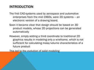
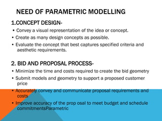
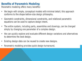
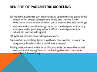
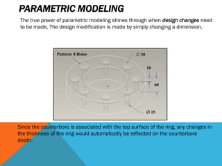
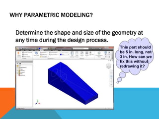


The document discusses parametric modeling and its benefits. Parametric modeling uses parameters to control dimensions and shapes in CAD models. When parameters are changed, related geometry is automatically updated based on design intent. This allows for easy design changes and exploration of design alternatives. Parametric modeling provides benefits like easier design revisions, rollback of design changes, and reuse of legacy data.


![libro de modelado de diseño-part-1[001-080].pdf](https://cdn.slidesharecdn.com/ss_thumbnails/librodemodeladodediseo-part-1001-080-240707154136-0bfed7ed-thumbnail.jpg?width=640&height=640&fit=bounds)