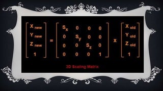
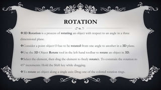
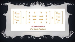
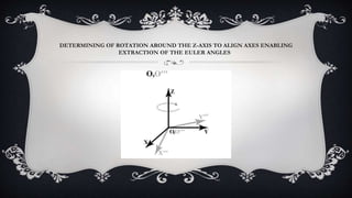
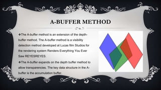
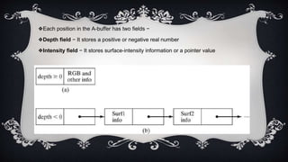
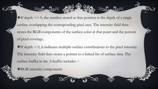
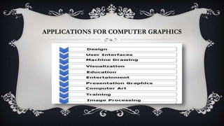
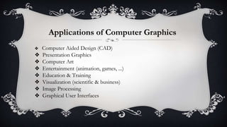
UNIT - V
❖3D Geometric and Modelling Transformation
❖Translation
❖Scaling
❖Rotation
❖Other transformation
❖Classification of visible surface detection algorithm
❖Back face detection
❖Depth-buffer method
❖A-buffer method
❖Scan line method
❖Applications of computer graphics
TRANSLATION :
❖A translation process moves every point a constant distance in a specified direction.
❖It can be described as a rigid motion.
❖A translation can also be interpreted as the addition of a constant vector to every point,
or as shifting the origin of the coordinate system.
❖There are four main types of transformations: translation, rotation, reflection and
dilation. These transformations fall into two categories: rigid transformations that do not
change the shape or size of the preimage and non-rigid transformations that change the
size but not the shape of the preimage.
In three-dimensional homogeneous coordinate representation.
a point is transformed from position P = (x, y, to P = (x ,y , )
This can be written as:
Translation
SCALING
❖Scaling may be used to increase or reduce the size of object.
❖Scaling subjects the coordinate points of the original object to change.
❖Scaling factor determines whether the object size is to be increased or
reduced.
❖If scaling factor > 1, then the object size is increased.
❖If scaling factor < 1, then the object size is reduced.
ROTATION
❖3D Rotation is a process of rotating an object with respect to an angle in a three
dimensional plane.
❖Consider a point object O has to be rotated from one angle to another in a 3D plane.
❖Use the 3D Object Rotate tool in the left-hand toolbar to rotate an object in 3D.
❖Select the element, then drag the element to freely rotateit. To constrain the rotation to
45° increments: Hold the Shift key while dragging.
❖To rotate an object along a single axis: Drag one of the colored rotation rings.
DETERMINING OF ROTATION AROUND THE Z-AXIS TO ALIGN AXES ENABLING
EXTRACTION OF THE EULER ANGLES
OTHER TRANSFORMATION
❖In plane geometry, a shear mapping is a linear map that displaces each point in fixed
direction, by an amount proportional to its signed distance from the line that is parallel to
that direction and goes through the origin.
❖This type of mapping is also called shear transformation, transvection, or
just shearing.
❖They are also useful in three dimensional viewing for obtaining general projection
transformation
CLASSIFICATION OF VISIBLE SURFACE
DETECTION ALGORITHM
❖When we view a picture containing non-transparent objects and surfaces, then we cannot see those objects
from view which are behind from objects closer to eye. We must remove these hidden surfaces to get a
realistic screen image. The identification and removal of these surfaces is called Hidden-surface problem.
❖There are two approaches for removing hidden surface problems − Object-Space method and Image-
space method. The Object-space method is implemented in physical coordinate system and image-space
method is implemented in screen coordinate system.
❖When we want to display a 3D object on a 2D screen, we need to identify those parts of a screen that are
visible from a chosen viewing position.
BACK FACE DETECTION
❖A fast and simple object-space method for identifying the back faces of a polyhedron is based on the "inside-
outside" tests. A point x,y,zx,y,z is "inside" a polygon surface with plane parameters A, B, C, and D if When an
inside point is along the line of sight to the surface, the polygon must be a back
face weareinsidethatfaceandcannotseethefrontofitfromourviewingpositionweareinsidethatfaceandcannotseethefro
ntofitfromourviewingposition.
❖We can simplify this test by considering the normal vector N to a polygon surface, which has Cartesian
components A,B,CA,B,C.
❖In general, if V is a vector in the viewing direction from the eye or"camera"or"camera"position, then this
polygon is a back face if
❖V.N > 0
❖Furthermore, if object descriptions are converted to projection coordinates and your viewing
direction is parallel to the viewing z-axis, then −
❖V = (0, 0, Vz) and V.N = VZC
❖So that we only need to consider the sign of C the component of the normal vector N.
❖In a right-handed viewing system with viewing direction along the negative ZVZVaxis, the
polygon is a back face if C < 0. Also, we cannot see any face whose normal has z component
C = 0, since your viewing direction is towards that polygon. Thus, in general, we can label any
polygon as a back face if its normal vector has a z component value −
❖C <= 0
DEPTH BUFFER METHOD
❖ In this method each surface is processed separately one pixel position at a time across the
surface. The depth values for a pixel are compared and the closest smallestz smallestz surface
determines the colour to be displayed in the frame buffer.
❖It is applied very efficiently on surfaces of polygon. Surfaces can be processed in any order. To
override the closer polygons from the far ones, two buffers named frame buffer and depth
buffer, are used.
❖Depth buffer is used to store depth values for x,yx,y position, as surfaces are
processed 0≤depth≤10≤depth≤1.
Algorithm
❖Step-1 − Set the buffer values −
❖Depth buffer x,yx,y = 0
❖Frame buffer x,yx,y = background colour
❖Step-2 − Process each polygon OneatatimeOneatatime
❖For each projected x,yx,y pixel position of a polygon, calculate depth z.
❖If Z > depth buffer x,yx,y
❖Compute surface colour,
❖set depth buffer x,yx,y = z,
❖frame buffer x,yx,y = surfacecolor x,y
A-BUFFER METHOD
❖The A-buffer method is an extension of the depth-
buffer method. The A-buffer method is a visibility
detection method developed at Lucas film Studios for
the rendering system Renders Everything You Ever
Saw REYESREYES.
❖The A-buffer expands on the depth buffer method to
allow transparencies. The key data structure in the A-
buffer is the accumulation buffer.
❖Each position in the A-buffer has two fields −
❖Depth field − It stores a positive or negative real number
❖Intensity field − It stores surface-intensity information or a pointer value
❖If depth >= 0, the number stored at that position is the depth of a single
surface overlapping the corresponding pixel area. The intensity field then
stores the RGB components of the surface color at that point and the percent
of pixel coverage.
❖If depth < 0, it indicates multiple-surface contributions to the pixel intensity.
The intensity field then stores a pointer to a linked list of surface data. The
surface buffer in the A-buffer includes −
❖RGB intensity components
❖Opacity Parameter
❖Depth
❖Percent of area coverage
❖Surface identifier
❖The algorithm proceeds just like the depth buffer
algorithm. The depth and opacity values are used to
determine the final color of a pixel.
SCAN LINE METHOD
❖It is an image-space method to identify visible surface.
❖ This method has a depth information for only single scan-line.
❖ In order to require one scan-line of depth values, we must group and process all
polygons intersecting a given scan-line at the same time before processing the next
scan-line.
❖Two important tables, edge table and polygon table, are maintained for this.
❖The Edge Table − It contains
coordinate endpoints of each line in the
scene, the inverse slope of each line, and
pointers into the polygon table to connect
edges to surfaces.
❖The Polygon Table − It contains the
plane coefficients, surface material
properties, other surface data, and may
be pointers to the edge table.
APPLICATIONS FOR COMPUTER GRAPHICS
Applications of Computer Graphics
❖ Computer Aided Design (CAD)
❖ Presentation Graphics
❖ Computer Art
❖ Entertainment (animation, games, ...)
❖ Education & Training
❖ Visualization (scientific & business)
❖ Image Processing
❖ Graphical User Interfaces
THANK YOU

UNIT-V

  • 1.
    UNIT - V ❖3DGeometric and Modelling Transformation ❖Translation ❖Scaling ❖Rotation ❖Other transformation ❖Classification of visible surface detection algorithm ❖Back face detection ❖Depth-buffer method ❖A-buffer method ❖Scan line method ❖Applications of computer graphics
  • 2.
    TRANSLATION : ❖A translationprocess moves every point a constant distance in a specified direction. ❖It can be described as a rigid motion. ❖A translation can also be interpreted as the addition of a constant vector to every point, or as shifting the origin of the coordinate system. ❖There are four main types of transformations: translation, rotation, reflection and dilation. These transformations fall into two categories: rigid transformations that do not change the shape or size of the preimage and non-rigid transformations that change the size but not the shape of the preimage.
  • 3.
    In three-dimensional homogeneouscoordinate representation. a point is transformed from position P = (x, y, to P = (x ,y , ) This can be written as: Translation
  • 4.
    SCALING ❖Scaling may beused to increase or reduce the size of object. ❖Scaling subjects the coordinate points of the original object to change. ❖Scaling factor determines whether the object size is to be increased or reduced. ❖If scaling factor > 1, then the object size is increased. ❖If scaling factor < 1, then the object size is reduced.
  • 6.
    ROTATION ❖3D Rotation isa process of rotating an object with respect to an angle in a three dimensional plane. ❖Consider a point object O has to be rotated from one angle to another in a 3D plane. ❖Use the 3D Object Rotate tool in the left-hand toolbar to rotate an object in 3D. ❖Select the element, then drag the element to freely rotateit. To constrain the rotation to 45° increments: Hold the Shift key while dragging. ❖To rotate an object along a single axis: Drag one of the colored rotation rings.
  • 8.
    DETERMINING OF ROTATIONAROUND THE Z-AXIS TO ALIGN AXES ENABLING EXTRACTION OF THE EULER ANGLES
  • 9.
    OTHER TRANSFORMATION ❖In planegeometry, a shear mapping is a linear map that displaces each point in fixed direction, by an amount proportional to its signed distance from the line that is parallel to that direction and goes through the origin. ❖This type of mapping is also called shear transformation, transvection, or just shearing. ❖They are also useful in three dimensional viewing for obtaining general projection transformation
  • 11.
    CLASSIFICATION OF VISIBLESURFACE DETECTION ALGORITHM ❖When we view a picture containing non-transparent objects and surfaces, then we cannot see those objects from view which are behind from objects closer to eye. We must remove these hidden surfaces to get a realistic screen image. The identification and removal of these surfaces is called Hidden-surface problem. ❖There are two approaches for removing hidden surface problems − Object-Space method and Image- space method. The Object-space method is implemented in physical coordinate system and image-space method is implemented in screen coordinate system. ❖When we want to display a 3D object on a 2D screen, we need to identify those parts of a screen that are visible from a chosen viewing position.
  • 12.
    BACK FACE DETECTION ❖Afast and simple object-space method for identifying the back faces of a polyhedron is based on the "inside- outside" tests. A point x,y,zx,y,z is "inside" a polygon surface with plane parameters A, B, C, and D if When an inside point is along the line of sight to the surface, the polygon must be a back face weareinsidethatfaceandcannotseethefrontofitfromourviewingpositionweareinsidethatfaceandcannotseethefro ntofitfromourviewingposition. ❖We can simplify this test by considering the normal vector N to a polygon surface, which has Cartesian components A,B,CA,B,C. ❖In general, if V is a vector in the viewing direction from the eye or"camera"or"camera"position, then this polygon is a back face if ❖V.N > 0
  • 13.
    ❖Furthermore, if objectdescriptions are converted to projection coordinates and your viewing direction is parallel to the viewing z-axis, then − ❖V = (0, 0, Vz) and V.N = VZC ❖So that we only need to consider the sign of C the component of the normal vector N. ❖In a right-handed viewing system with viewing direction along the negative ZVZVaxis, the polygon is a back face if C < 0. Also, we cannot see any face whose normal has z component C = 0, since your viewing direction is towards that polygon. Thus, in general, we can label any polygon as a back face if its normal vector has a z component value − ❖C <= 0
  • 15.
    DEPTH BUFFER METHOD ❖In this method each surface is processed separately one pixel position at a time across the surface. The depth values for a pixel are compared and the closest smallestz smallestz surface determines the colour to be displayed in the frame buffer. ❖It is applied very efficiently on surfaces of polygon. Surfaces can be processed in any order. To override the closer polygons from the far ones, two buffers named frame buffer and depth buffer, are used. ❖Depth buffer is used to store depth values for x,yx,y position, as surfaces are processed 0≤depth≤10≤depth≤1.
  • 16.
    Algorithm ❖Step-1 − Setthe buffer values − ❖Depth buffer x,yx,y = 0 ❖Frame buffer x,yx,y = background colour ❖Step-2 − Process each polygon OneatatimeOneatatime ❖For each projected x,yx,y pixel position of a polygon, calculate depth z. ❖If Z > depth buffer x,yx,y ❖Compute surface colour, ❖set depth buffer x,yx,y = z, ❖frame buffer x,yx,y = surfacecolor x,y
  • 18.
    A-BUFFER METHOD ❖The A-buffermethod is an extension of the depth- buffer method. The A-buffer method is a visibility detection method developed at Lucas film Studios for the rendering system Renders Everything You Ever Saw REYESREYES. ❖The A-buffer expands on the depth buffer method to allow transparencies. The key data structure in the A- buffer is the accumulation buffer.
  • 19.
    ❖Each position inthe A-buffer has two fields − ❖Depth field − It stores a positive or negative real number ❖Intensity field − It stores surface-intensity information or a pointer value
  • 20.
    ❖If depth >=0, the number stored at that position is the depth of a single surface overlapping the corresponding pixel area. The intensity field then stores the RGB components of the surface color at that point and the percent of pixel coverage. ❖If depth < 0, it indicates multiple-surface contributions to the pixel intensity. The intensity field then stores a pointer to a linked list of surface data. The surface buffer in the A-buffer includes − ❖RGB intensity components
  • 21.
    ❖Opacity Parameter ❖Depth ❖Percent ofarea coverage ❖Surface identifier ❖The algorithm proceeds just like the depth buffer algorithm. The depth and opacity values are used to determine the final color of a pixel.
  • 22.
    SCAN LINE METHOD ❖Itis an image-space method to identify visible surface. ❖ This method has a depth information for only single scan-line. ❖ In order to require one scan-line of depth values, we must group and process all polygons intersecting a given scan-line at the same time before processing the next scan-line. ❖Two important tables, edge table and polygon table, are maintained for this.
  • 23.
    ❖The Edge Table− It contains coordinate endpoints of each line in the scene, the inverse slope of each line, and pointers into the polygon table to connect edges to surfaces. ❖The Polygon Table − It contains the plane coefficients, surface material properties, other surface data, and may be pointers to the edge table.
  • 24.
  • 25.
    Applications of ComputerGraphics ❖ Computer Aided Design (CAD) ❖ Presentation Graphics ❖ Computer Art ❖ Entertainment (animation, games, ...) ❖ Education & Training ❖ Visualization (scientific & business) ❖ Image Processing ❖ Graphical User Interfaces
  • 26.