Downloaded 265 times


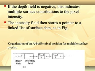


The document discusses visible-surface detection algorithms, classifying them into object-space and image-space methods. It details techniques such as back-face detection, depth-buffer method, a-buffer method, and scan-line method for identifying visible surfaces in 3D graphics. Each method has specific applications and limitations related to surface visibility and depth sorting.