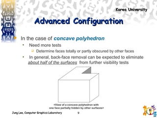
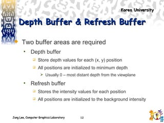
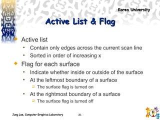
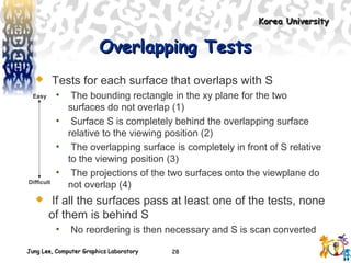
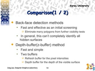
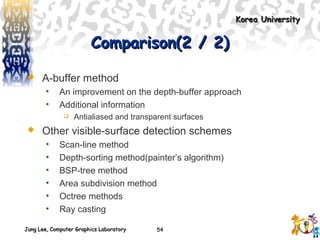
This document discusses various visible surface detection methods in computer graphics. It introduces common image-space and object-space classification methods. Specific algorithms covered include back-face detection, depth buffer, scan-line, depth sorting, and their characteristics and processes. The document concludes with a comparison of these visible surface detection methods.
it is a Visible surface detection method is also known as depth buffer method. In this method detect the visible surface by using the distance of the object from the projections plane.
An illumination model, also called a lighting model and sometimes referred to as a shading model, is used to calculate the intensity of light that we should see at a given point on the surface of an object.
Comprehensive coverage of fundamentals of computer graphics.
3D Transformations
Reflections
3D Display methods
3D Object Representation
Polygon surfaces
Quadratic Surfaces
Identify those parts of a scene that are visible from a chosen viewing position.
Visible-surface detection algorithms are broadly classified according to whether
they deal with object definitions directly or with their projected images.
These two approaches are called object-space methods and image-space methods, respectively
An object-space method compares
objects and parts of objects to each other within the scene definition to determine which surfaces, as a whole, we should label as visible.
In an image-space algorithm, visibility is decided point by point at each pixel position on the projection plane.
An illumination model, also called a lighting model and sometimes referred to as a shading model, is used to calculate the intensity of light that we should see at a given point on the surface of an object.
Surface rendering means a procedure for applying a lighting model to obtain pixel intensities for all the projected surface positions in a scene.
A surface-rendering algorithm uses the intensity calculations from an illumination model to determine the light intensity for all projected pixel positions for the various surfaces in a scene.
Surface rendering can be performed by applying the illumination model to every visible surface point.
Fundamental steps in Digital Image ProcessingShubham Jain
Fundamental Steps in Digital Image Processing: Image acquisition, enhancement, restoration, etc. For written notes and pdf visit: https://buzztech.in/fundamental-steps-in-digital-image-processing
Defect detection in circlips using image processing in ni lab viewSayali Bodhankar
A circlip (circular-clip) is a semi-flexible metal ring used as a fastener in advanced industrial machinery. Faults or defects in the circlip can cause the entire machinery to fall off. Hence, sorting of circlips as "good" or "faulty" is imperative.
발표자: 고영준 (고려대 박사과정)
발표일: 2017.6.
개요:
Algorithms to segment objects in a video sequence will be presented.
First, I will introduce a primary object segmentation algorithm based on region augmentation and reduction. Second, collaborative detection, tracking, and segmentation for online multiple object segmentation will be presented.
Morphological image processing is a collection of non- linear operations related to the shape or morphology of features in an image.
Morphological Image processing is discussed in a brief manner
Water scarcity is the lack of fresh water resources to meet the standard water demand. There are two type of water scarcity. One is physical. The other is economic water scarcity.
CFD Simulation of By-pass Flow in a HRSG module by R&R Consult.pptxR&R Consult
CFD analysis is incredibly effective at solving mysteries and improving the performance of complex systems!
Here's a great example: At a large natural gas-fired power plant, where they use waste heat to generate steam and energy, they were puzzled that their boiler wasn't producing as much steam as expected.
R&R and Tetra Engineering Group Inc. were asked to solve the issue with reduced steam production.
An inspection had shown that a significant amount of hot flue gas was bypassing the boiler tubes, where the heat was supposed to be transferred.
R&R Consult conducted a CFD analysis, which revealed that 6.3% of the flue gas was bypassing the boiler tubes without transferring heat. The analysis also showed that the flue gas was instead being directed along the sides of the boiler and between the modules that were supposed to capture the heat. This was the cause of the reduced performance.
Based on our results, Tetra Engineering installed covering plates to reduce the bypass flow. This improved the boiler's performance and increased electricity production.
It is always satisfying when we can help solve complex challenges like this. Do your systems also need a check-up or optimization? Give us a call!
Work done in cooperation with James Malloy and David Moelling from Tetra Engineering.
More examples of our work https://www.r-r-consult.dk/en/cases-en/
Quality defects in TMT Bars, Possible causes and Potential Solutions.PrashantGoswami42
Maintaining high-quality standards in the production of TMT bars is crucial for ensuring structural integrity in construction. Addressing common defects through careful monitoring, standardized processes, and advanced technology can significantly improve the quality of TMT bars. Continuous training and adherence to quality control measures will also play a pivotal role in minimizing these defects.
Hybrid optimization of pumped hydro system and solar- Engr. Abdul-Azeez.pdffxintegritypublishin
Advancements in technology unveil a myriad of electrical and electronic breakthroughs geared towards efficiently harnessing limited resources to meet human energy demands. The optimization of hybrid solar PV panels and pumped hydro energy supply systems plays a pivotal role in utilizing natural resources effectively. This initiative not only benefits humanity but also fosters environmental sustainability. The study investigated the design optimization of these hybrid systems, focusing on understanding solar radiation patterns, identifying geographical influences on solar radiation, formulating a mathematical model for system optimization, and determining the optimal configuration of PV panels and pumped hydro storage. Through a comparative analysis approach and eight weeks of data collection, the study addressed key research questions related to solar radiation patterns and optimal system design. The findings highlighted regions with heightened solar radiation levels, showcasing substantial potential for power generation and emphasizing the system's efficiency. Optimizing system design significantly boosted power generation, promoted renewable energy utilization, and enhanced energy storage capacity. The study underscored the benefits of optimizing hybrid solar PV panels and pumped hydro energy supply systems for sustainable energy usage. Optimizing the design of solar PV panels and pumped hydro energy supply systems as examined across diverse climatic conditions in a developing country, not only enhances power generation but also improves the integration of renewable energy sources and boosts energy storage capacities, particularly beneficial for less economically prosperous regions. Additionally, the study provides valuable insights for advancing energy research in economically viable areas. Recommendations included conducting site-specific assessments, utilizing advanced modeling tools, implementing regular maintenance protocols, and enhancing communication among system components.
Automobile Management System Project Report.pdfKamal Acharya
The proposed project is developed to manage the automobile in the automobile dealer company. The main module in this project is login, automobile management, customer management, sales, complaints and reports. The first module is the login. The automobile showroom owner should login to the project for usage. The username and password are verified and if it is correct, next form opens. If the username and password are not correct, it shows the error message.
When a customer search for a automobile, if the automobile is available, they will be taken to a page that shows the details of the automobile including automobile name, automobile ID, quantity, price etc. “Automobile Management System” is useful for maintaining automobiles, customers effectively and hence helps for establishing good relation between customer and automobile organization. It contains various customized modules for effectively maintaining automobiles and stock information accurately and safely.
When the automobile is sold to the customer, stock will be reduced automatically. When a new purchase is made, stock will be increased automatically. While selecting automobiles for sale, the proposed software will automatically check for total number of available stock of that particular item, if the total stock of that particular item is less than 5, software will notify the user to purchase the particular item.
Also when the user tries to sale items which are not in stock, the system will prompt the user that the stock is not enough. Customers of this system can search for a automobile; can purchase a automobile easily by selecting fast. On the other hand the stock of automobiles can be maintained perfectly by the automobile shop manager overcoming the drawbacks of existing system.
Sachpazis:Terzaghi Bearing Capacity Estimation in simple terms with Calculati...Dr.Costas Sachpazis
Terzaghi's soil bearing capacity theory, developed by Karl Terzaghi, is a fundamental principle in geotechnical engineering used to determine the bearing capacity of shallow foundations. This theory provides a method to calculate the ultimate bearing capacity of soil, which is the maximum load per unit area that the soil can support without undergoing shear failure. The Calculation HTML Code included.
Vaccine management system project report documentation..pdfKamal Acharya
The Division of Vaccine and Immunization is facing increasing difficulty monitoring vaccines and other commodities distribution once they have been distributed from the national stores. With the introduction of new vaccines, more challenges have been anticipated with this additions posing serious threat to the already over strained vaccine supply chain system in Kenya.
Courier management system project report.pdfKamal Acharya
It is now-a-days very important for the people to send or receive articles like imported furniture, electronic items, gifts, business goods and the like. People depend vastly on different transport systems which mostly use the manual way of receiving and delivering the articles. There is no way to track the articles till they are received and there is no way to let the customer know what happened in transit, once he booked some articles. In such a situation, we need a system which completely computerizes the cargo activities including time to time tracking of the articles sent. This need is fulfilled by Courier Management System software which is online software for the cargo management people that enables them to receive the goods from a source and send them to a required destination and track their status from time to time.
About
Indigenized remote control interface card suitable for MAFI system CCR equipment. Compatible for IDM8000 CCR. Backplane mounted serial and TCP/Ethernet communication module for CCR remote access. IDM 8000 CCR remote control on serial and TCP protocol.
• Remote control: Parallel or serial interface.
• Compatible with MAFI CCR system.
• Compatible with IDM8000 CCR.
• Compatible with Backplane mount serial communication.
• Compatible with commercial and Defence aviation CCR system.
• Remote control system for accessing CCR and allied system over serial or TCP.
• Indigenized local Support/presence in India.
• Easy in configuration using DIP switches.
Technical Specifications
Indigenized remote control interface card suitable for MAFI system CCR equipment. Compatible for IDM8000 CCR. Backplane mounted serial and TCP/Ethernet communication module for CCR remote access. IDM 8000 CCR remote control on serial and TCP protocol.
Key Features
Indigenized remote control interface card suitable for MAFI system CCR equipment. Compatible for IDM8000 CCR. Backplane mounted serial and TCP/Ethernet communication module for CCR remote access. IDM 8000 CCR remote control on serial and TCP protocol.
• Remote control: Parallel or serial interface
• Compatible with MAFI CCR system
• Copatiable with IDM8000 CCR
• Compatible with Backplane mount serial communication.
• Compatible with commercial and Defence aviation CCR system.
• Remote control system for accessing CCR and allied system over serial or TCP.
• Indigenized local Support/presence in India.
Application
• Remote control: Parallel or serial interface.
• Compatible with MAFI CCR system.
• Compatible with IDM8000 CCR.
• Compatible with Backplane mount serial communication.
• Compatible with commercial and Defence aviation CCR system.
• Remote control system for accessing CCR and allied system over serial or TCP.
• Indigenized local Support/presence in India.
• Easy in configuration using DIP switches.
3. Jung Lee, Computer Graphics LaboratoryJung Lee, Computer Graphics Laboratory
Korea UniversityKorea University
3
AbstractAbstract
Hidden-surface elimination methods
Identifying visible parts of a scene from a viewpoint
Numerous algorithms
• More memory - storage
• More processing time – execution time
• Only for special types of objects - constraints
Deciding a method for a particular application
• Complexity of the scene
• Type of objects
• Available equipment
• Static or animated scene
<Ex. Wireframe Displays>
5. Jung Lee, Computer Graphics LaboratoryJung Lee, Computer Graphics Laboratory
Korea UniversityKorea University
5
Classification of Visible-SurfaceClassification of Visible-Surface
Detection AlgorithmsDetection Algorithms
Object-space methods vs. Image-space methods
• Object definition directly vs. their projected images
• Most visible-surface algorithms use image-space methods
• Object-space can be used effectively in some cases
Ex) Line-display algorithms
Object-space methods
• Compares objects and parts of objects to each other
Image-space methods
• Point by point at each pixel position on the projection plane
6. Jung Lee, Computer Graphics LaboratoryJung Lee, Computer Graphics Laboratory
Korea UniversityKorea University
6
Sorting and Coherence MethodsSorting and Coherence Methods
To improve performance
Sorting
• Facilitate depth comparisons
Ordering the surfaces according to their distance from
the viewplane
Coherence
• Take advantage of regularity
Epipolar geometry
Topological coherence
8. Jung Lee, Computer Graphics LaboratoryJung Lee, Computer Graphics Laboratory
Korea UniversityKorea University
8
Inside-outside testInside-outside test
A point (x, y, z) is “inside” a surface with plane
parameters A, B, C, and D if
The polygon is a back face if
• V is a vector in the viewing direction from the eye(camera)
• N is the normal vector to a polygon surface
0<+++ DCzByAx
0>⋅ NV V
N = (A, B, C)
9. Jung Lee, Computer Graphics LaboratoryJung Lee, Computer Graphics Laboratory
Korea UniversityKorea University
9
Advanced ConfigurationAdvanced Configuration
In the case of concave polyhedron
• Need more tests
Determine faces totally or partly obscured by other faces
• In general, back-face removal can be expected to eliminate
about half of the surfaces from further visibility tests
<View of a concave polyhedron with
one face partially hidden by other surfaces>
11. Jung Lee, Computer Graphics LaboratoryJung Lee, Computer Graphics Laboratory
Korea UniversityKorea University
11
CharacteristicsCharacteristics
Commonly used image-space approach
Compares depths of each pixel on the projection
plane
• Referred to as the z-buffer method
Usually applied to scenes of polygonal surfaces
• Depth values can be computed very quickly
• Easy to implement
Yv
Xv
Zv
S1
S2
S3
(x, y)
12. Jung Lee, Computer Graphics LaboratoryJung Lee, Computer Graphics Laboratory
Korea UniversityKorea University
12
Depth Buffer & Refresh BufferDepth Buffer & Refresh Buffer
Two buffer areas are required
• Depth buffer
Store depth values for each (x, y) position
All positions are initialized to minimum depth
Usually 0 – most distant depth from the viewplane
• Refresh buffer
Stores the intensity values for each position
All positions are initialized to the background intensity
13. Jung Lee, Computer Graphics LaboratoryJung Lee, Computer Graphics Laboratory
Korea UniversityKorea University
13
AlgorithmAlgorithm
Initialize the depth buffer and refresh buffer
depth(x, y) = 0, refresh(x, y) = Ibackgnd
For each position on each polygon surface
• Calculate the depth for each (x, y) position on the polygon
• If z > depth(x, y), then set
depth(x, y) = z, refresh(x, y) = Isurf(x, y)
Advanced
• With resolution of 1024 by 1024
Over a million positions in the depth buffer
• Process one section of the scene at a time
Need a smaller depth buffer
The buffer is reused for the next section
15. Jung Lee, Computer Graphics LaboratoryJung Lee, Computer Graphics Laboratory
Korea UniversityKorea University
19
CharacteristicsCharacteristics
Extension of the scan-line algorithm for filling
polygon interiors
• For all polygons intersecting each scan line
Processed from left to right
Depth calculations for each overlapping surface
The intensity of the nearest position is entered into the
refresh buffer
16. Jung Lee, Computer Graphics LaboratoryJung Lee, Computer Graphics Laboratory
Korea UniversityKorea University
20
Tables for The Various SurfacesTables for The Various Surfaces
Edge table
• Coordinate endpoints for each line
• Slope of each line
• Pointers into the polygon table
Identify the surfaces bounded by each line
Polygon table
• Coefficients of the plane equation for each surface
• Intensity information for the surfaces
• Pointers into the edge table
17. Jung Lee, Computer Graphics LaboratoryJung Lee, Computer Graphics Laboratory
Korea UniversityKorea University
21
Active List & FlagActive List & Flag
Active list
• Contain only edges across the current scan line
• Sorted in order of increasing x
Flag for each surface
• Indicate whether inside or outside of the surface
• At the leftmost boundary of a surface
The surface flag is turned on
• At the rightmost boundary of a surface
The surface flag is turned off
18. Jung Lee, Computer Graphics LaboratoryJung Lee, Computer Graphics Laboratory
Korea UniversityKorea University
22
ExampleExample
Active list for scan line 1
• Edge table
AB, BC, EH, and FG
Between AB and BC, only
the flag for surface S1 is on
No depth calculations are necessary
Intensity for surface S1 is entered into the refresh buffer
Similarly, between EH and FG, only the flag for S2 is on
xv
yv
A
B
S1
E
F
S2
H
D
C
G
Scan line 1
Scan line 2
Scan line 3
19. Jung Lee, Computer Graphics LaboratoryJung Lee, Computer Graphics Laboratory
Korea UniversityKorea University
23
Example(cont.)Example(cont.)
For scan line 2, 3
• AD, EH, BC, and FG
Between AD and EH, only the flag for S1 is on
Between EH and BC, the flags for both surfaces are on
Depth calculation is needed
Intensities for S1 are loaded into the refresh buffer until
BC
• Take advantage of coherence
Pass from one scan line to next
Scan line 3 has the same active list as scan line 2
Unnecessary to make depth calculations between EH
and BC
20. Jung Lee, Computer Graphics LaboratoryJung Lee, Computer Graphics Laboratory
Korea UniversityKorea University
24
DrawbackDrawback
Only if surfaces don’t cut through or
otherwise cyclically overlap each other
• If any kind of cyclic overlap is present
Divide the surfaces
22. Jung Lee, Computer Graphics LaboratoryJung Lee, Computer Graphics Laboratory
Korea UniversityKorea University
26
OperationsOperations
Image-space and object-space operations
• Sorting operations in both image and object-
space
• The scan conversion of polygon surfaces in
image-space
Basic functions
• Surfaces are sorted in order of decreasing depth
• Surfaces are scan-converted in order, starting
with the surface of greatest depth
23. Jung Lee, Computer Graphics LaboratoryJung Lee, Computer Graphics Laboratory
Korea UniversityKorea University
27
AlgorithmAlgorithm
Referred to as the painter’s algorithm
• In creating an oil painting
First paints the background colors
The most distant objects are added
Then the nearer objects, and so forth
Finally, the foregrounds are painted over all objects
• Each layer of paint covers up the previous layer
Process
• Sort surfaces according to their distance from the
viewplane
• The intensities for the farthest surface are then entered
into the refresh buffer
• Taking each succeeding surface in decreasing depth order
24. Jung Lee, Computer Graphics LaboratoryJung Lee, Computer Graphics Laboratory
Korea UniversityKorea University
28
Overlapping TestsOverlapping Tests
Tests for each surface that overlaps with S
• The bounding rectangle in the xy plane for the two
surfaces do not overlap (1)
• Surface S is completely behind the overlapping surface
relative to the viewing position (2)
• The overlapping surface is completely in front of S relative
to the viewing position (3)
• The projections of the two surfaces onto the viewplane do
not overlap (4)
If all the surfaces pass at least one of the tests, none
of them is behind S
• No reordering is then necessary and S is scan converted
Easy
Difficult
25. Jung Lee, Computer Graphics LaboratoryJung Lee, Computer Graphics Laboratory
Korea UniversityKorea University
29
Overlapping Test ExamplesOverlapping Test Examples
zv
xv
S
S’
zv
xv
S
S’
zv
xv
zv
xv
S
S’
(1) (2)
(3) (4)
26. Jung Lee, Computer Graphics LaboratoryJung Lee, Computer Graphics Laboratory
Korea UniversityKorea University
30
Surface ReorderingSurface Reordering
If all four tests fail with S’
• Interchange surfaces S and S’ in the sorted list
• Repeat the tests for each surface that is
reordered in the list
zv
xv
SS’
<S S’> zv
xv
S
S’
S’’
<S S’’, then S’’ S’>
27. Jung Lee, Computer Graphics LaboratoryJung Lee, Computer Graphics Laboratory
Korea UniversityKorea University
31
DrawbackDrawback
If two or more surfaces alternately obscure
each other
• Infinite loop
• Flag any surface that has been reordered to a
farther depth
It can’t be moved again
• If an attempt to switch the surface a second time
Divide it into two parts to eliminate the cyclic loop
The original surface is then replaced by the two new
surfaces
29. Jung Lee, Computer Graphics LaboratoryJung Lee, Computer Graphics Laboratory
Korea UniversityKorea University
53
Comparison(1 / 2)Comparison(1 / 2)
Back-face detection methods
• Fast and effective as an initial screening
Eliminate many polygons from further visibility tests
• In general, this can’t completely identify all
hidden surfaces
Depth-buffer(z-buffer) method
• Fast and simple
• Two buffers
Refresh buffer for the pixel intensities
Depth buffer for the depth of the visible surface
30. Jung Lee, Computer Graphics LaboratoryJung Lee, Computer Graphics Laboratory
Korea UniversityKorea University
54
Comparison(2 / 2)Comparison(2 / 2)
A-buffer method
• An improvement on the depth-buffer approach
• Additional information
Antialiased and transparent surfaces
Other visible-surface detection schemes
• Scan-line method
• Depth-sorting method(painter’s algorithm)
• BSP-tree method
• Area subdivision method
• Octree methods
• Ray casting