Downloaded 42 times
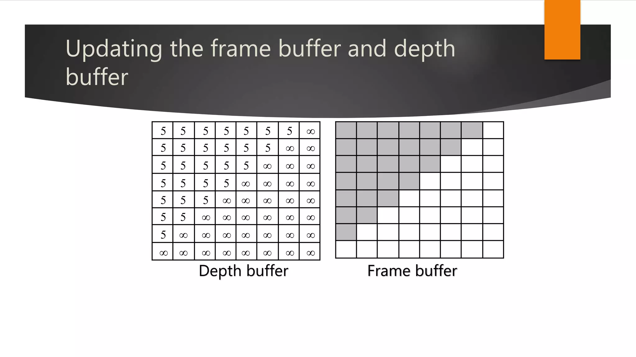
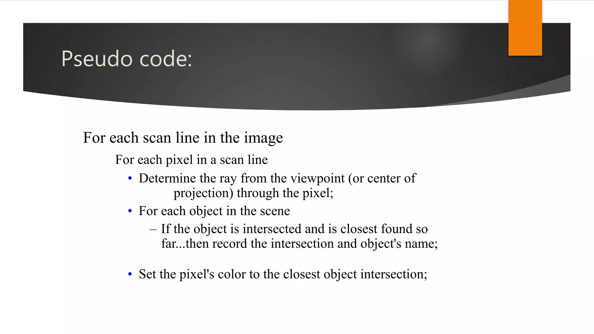
![Pseudo code
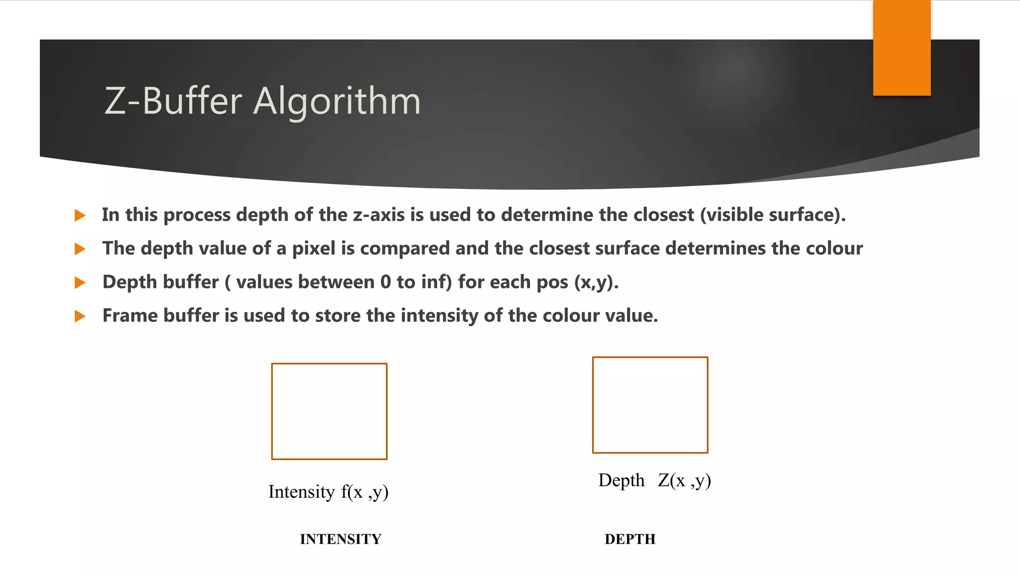
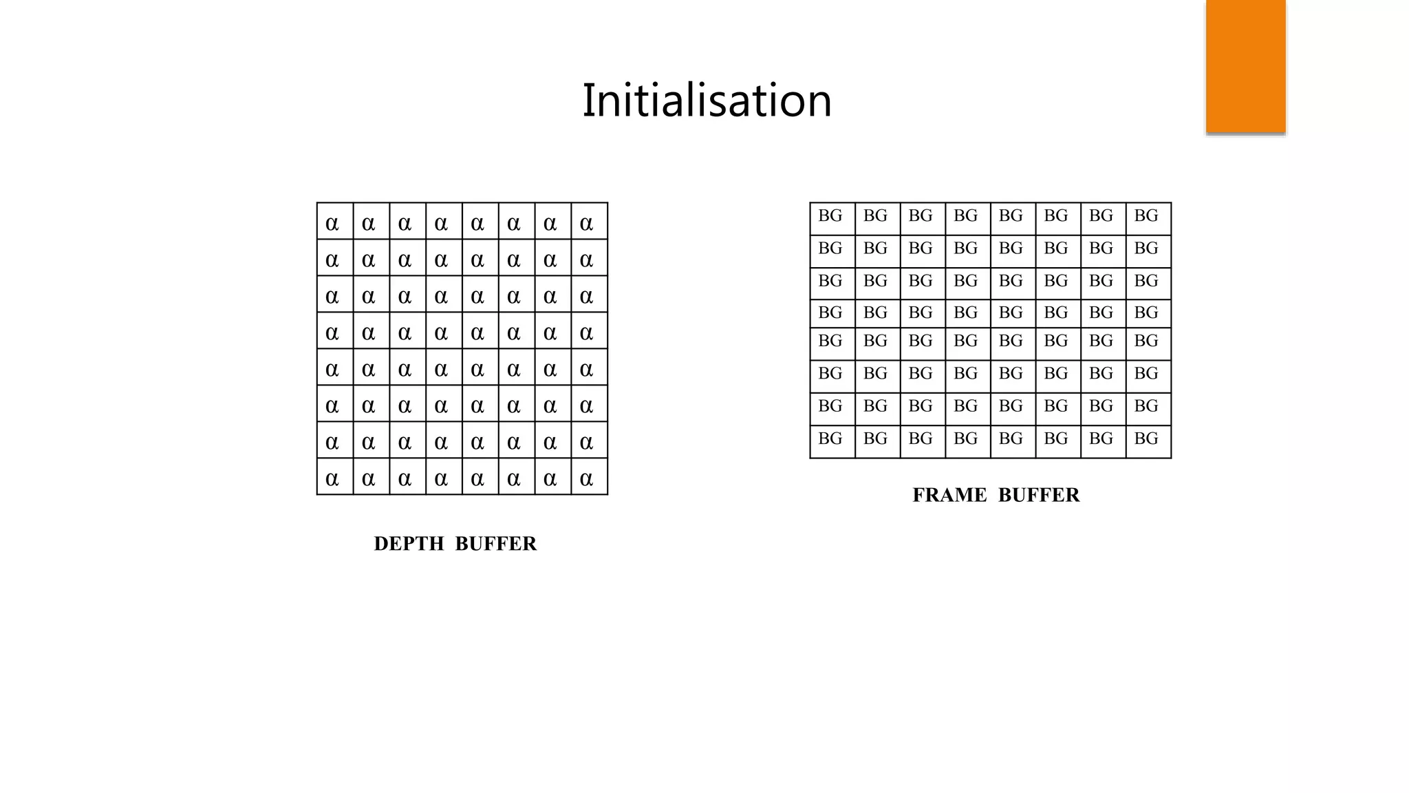
Initialize all d[i,j]=inf (max depth), c[i,j]=background color.
for (each polygon)
{
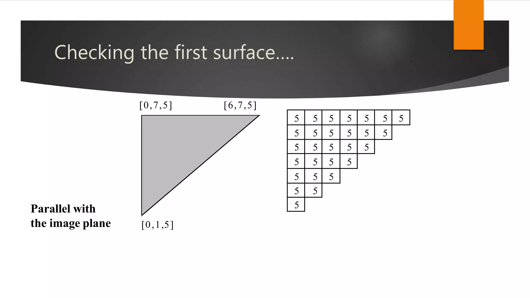
for (each pixel in polygon’s projection)
{
Find depth-z of polygon at (x,y) corresponding to pixel (i,j);
If z < d[i,j]
{
d[i,j] = z;
p[i,j] = color;
}
}
}](https://image.slidesharecdn.com/hiddensurfaceremoval-171211083602/75/Hidden-surface-removal-13-2048.jpg)
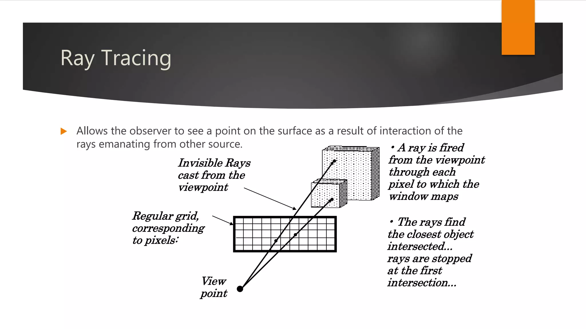


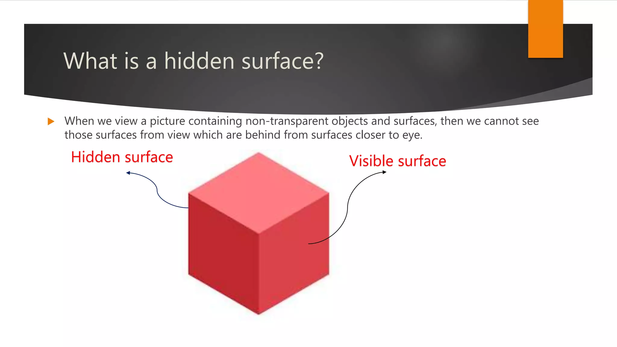
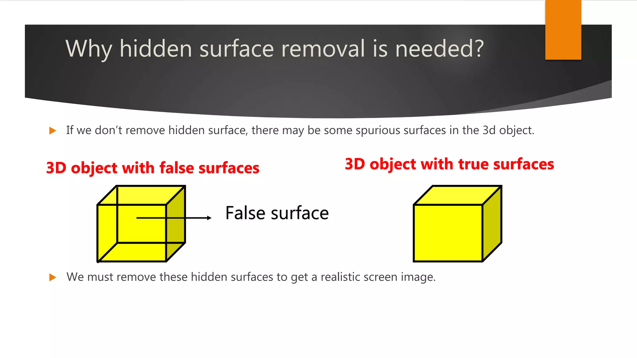
The document discusses hidden surface removal techniques in 3D graphics, emphasizing its necessity for realistic rendering by eliminating spurious surfaces. It outlines two main approaches: object space and image space, detailing algorithms like Roberts, Z-buffer, and ray tracing. Additionally, it describes the mechanics of Z-buffering, ray tracing, and the computational costs associated with different methods.