The document describes the Z-buffer algorithm for hidden surface removal in 3D graphics. The Z-buffer algorithm works by processing each surface individually and comparing the depth (z-coordinate) of pixels across surfaces. Pixels with smaller z-values, which are closer to the viewpoint, are determined to be visible and their color values are written to the frame buffer. A depth buffer stores the z-value of each pixel to track the closest surface at that point. This algorithm efficiently handles polygon surfaces by processing them in any order and using the depth and frame buffers to override closer polygons.
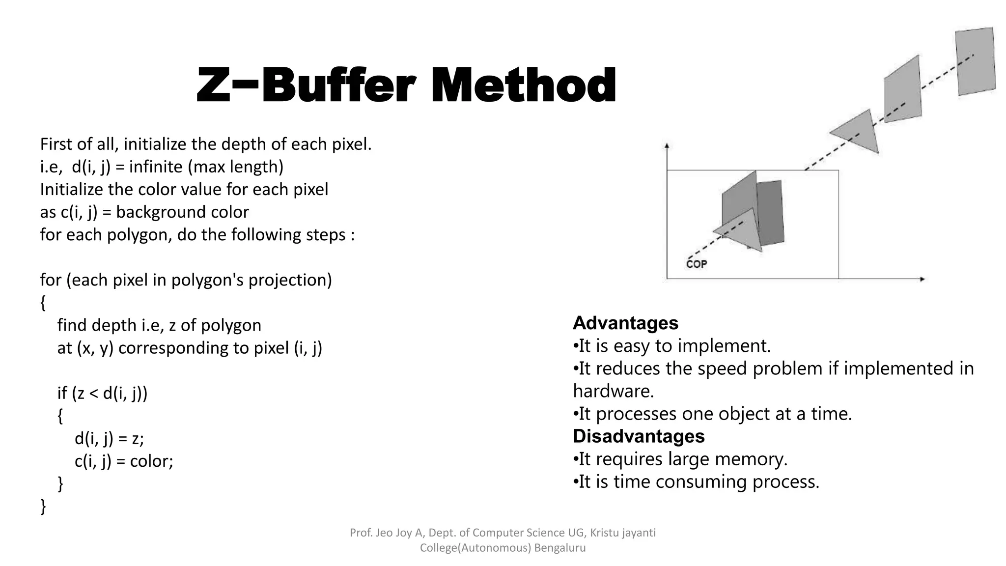
![• This method is developed by Cutmull. It is an image-space approach. The basic idea is to test the Z-
depth of each surface to determine the closest visible surface.
• In this method each surface is processed separately one pixel position at a time across the surface.
The depth values for a pixel are compared and the closest smallest z surface determines the color to
be displayed in the frame buffer.
• It is applied very efficiently on surfaces of polygon. Surfaces can be processed in any order. To
override the closer polygons from the far ones, two buffers named frame buffer and depth buffer,
are used.
• Depth buffer is used to store depth values for x,y position, as surfaces are processed 0≤depth≤1.
• The frame buffer is used to store the intensity value of color value at each position x,y.
• The z-coordinates are usually normalized to the range [0, 1]. The 0 value for z-coordinate indicates
back clipping pane and 1 value for z-coordinates indicates front clipping pane.
Z−Buffer Method
Prof. Jeo Joy A, Dept. of Computer Science UG, Kristu jayanti
College(Autonomous) Bengaluru](https://image.slidesharecdn.com/visiblesurfactedetectionmethods-z-bufferandscanlinemethods-221226040331-c03796aa/75/Visible-Surfacte-Detection-Methods-Z-Buffer-and-Scanline-methods-pptx-2-2048.jpg)
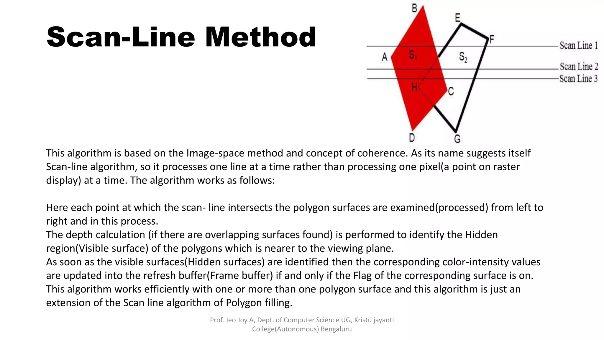
![Scan-Line Method
Prof. Jeo Joy A, Dept. of Computer Science UG, Kristu jayanti
College(Autonomous) Bengaluru
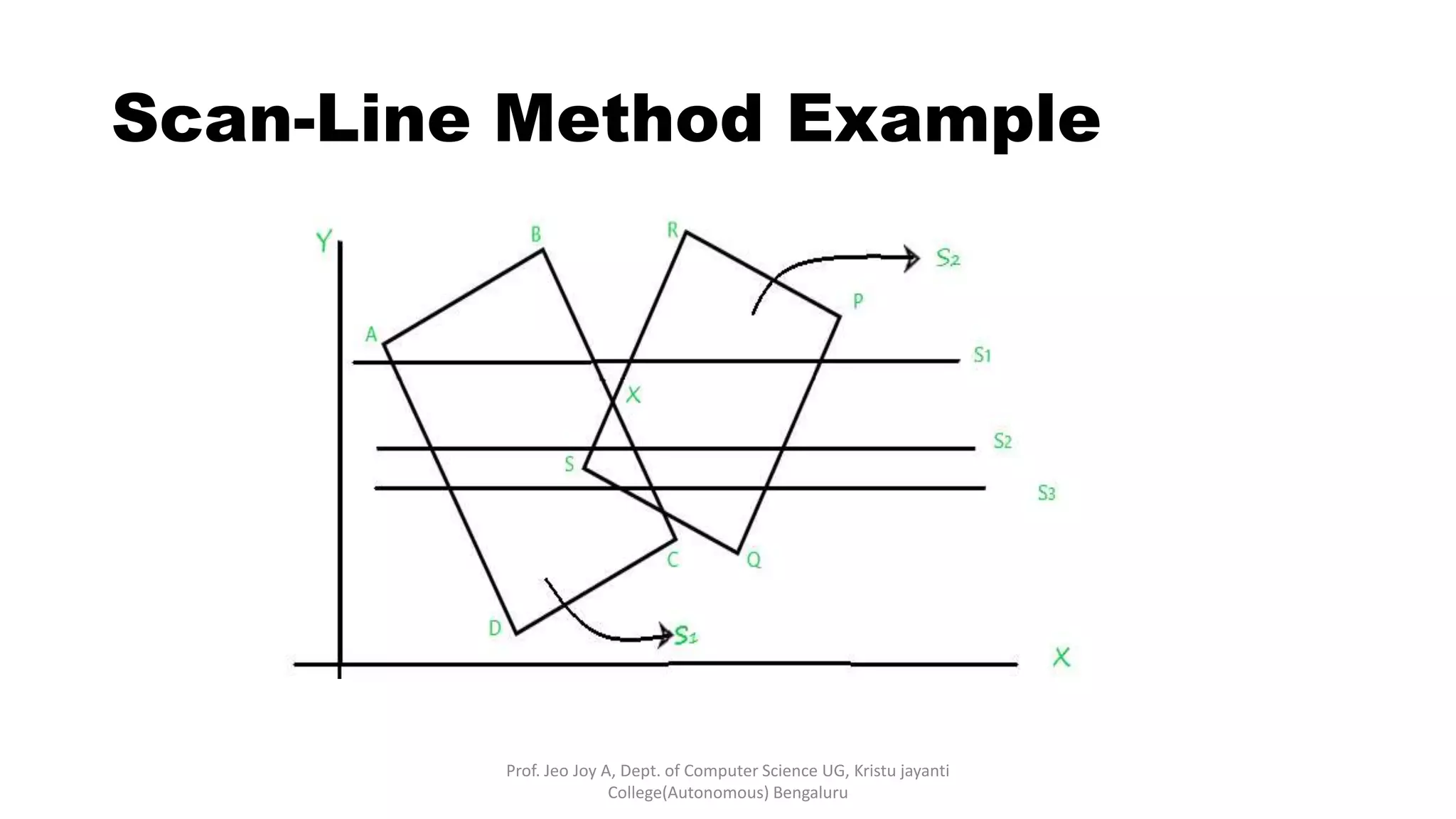
Here, two overlapped polygons are given which are intersected
by three Scan-lines S1, S2, S3 respectively. So, What happens if
the Scan-line algorithm is applied in order to identify the
Hidden surface(visible surface)?
1. First, examine the scanline(S1), whose,
Active edge table (Aet) contains: [AD,BC,RS,PQ], and
The flag is set to “on” for surface(S1) and surface(S2) and the flag set
“off” for the region between BX and RX as it’s an outer region of the
polygon’s surface and not to be projected at view-port(display
devices), now
Drop the color-intensities of the corresponding surfaces into the
frame buffer(refresh buffer).](https://image.slidesharecdn.com/visiblesurfactedetectionmethods-z-bufferandscanlinemethods-221226040331-c03796aa/75/Visible-Surfacte-Detection-Methods-Z-Buffer-and-Scanline-methods-pptx-6-2048.jpg)
![Scan-Line Method
Prof. Jeo Joy A, Dept. of Computer Science UG, Kristu jayanti
College(Autonomous) Bengaluru
2. Then, process the scanline(S2), whose,
Active edge table (Aet) contains: [AD,BC,RS,PQ], and
The flag is set to “on” for surface(ABCD) and surface(PQRS),
Both of the polygons surfaces are overlapping each other so for
this overlapped region which of the surface intensity should be
taken into account? So to answer this calculates the
depth(Zmin) of both surface(S1) and surface(S2) of this
overlapped portion, next,
If depth(S1)>depth(S2), then the Flag of surface S1=” on” and
intensity of surface S1 will be considered else S2, now
Drop the color-intensities of the corresponding surfaces whose
flag is set to on into the frame buffer(refresh buffer).](https://image.slidesharecdn.com/visiblesurfactedetectionmethods-z-bufferandscanlinemethods-221226040331-c03796aa/75/Visible-Surfacte-Detection-Methods-Z-Buffer-and-Scanline-methods-pptx-7-2048.jpg)