Download to read offline
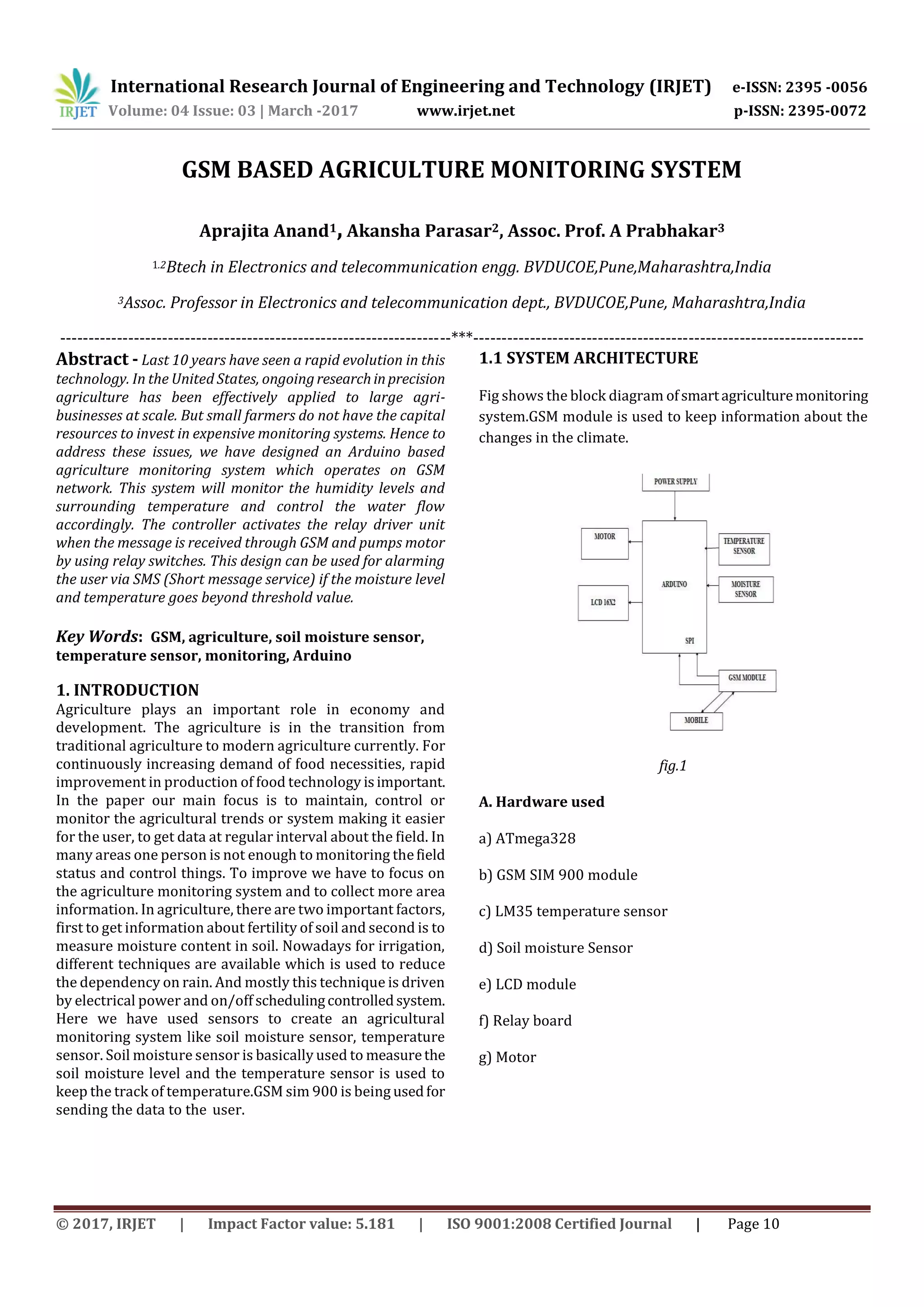


This document describes an agriculture monitoring system that uses sensors to measure soil moisture and temperature, and sends alerts via SMS if the measurements exceed thresholds. The system includes an Arduino board connected to sensors for soil moisture and temperature, as well as a GSM module. The sensors continuously monitor conditions and transmit readings to users' phones via the GSM module if the moisture or temperature levels go above or below set points. This low-cost system allows small farmers to remotely monitor field conditions without expensive dedicated equipment.