What are the advantages and disadvantages of membrane structures.pptx
iot1&2.pdf
1. 14
Experiment No. 1
AIM: Getting information and study of IOT microcontrollers (Arduino and Raspberry Pi)
1. Theory
PART A: Study on Arduino Board
1.1 Introduction to Arduino Uno Board
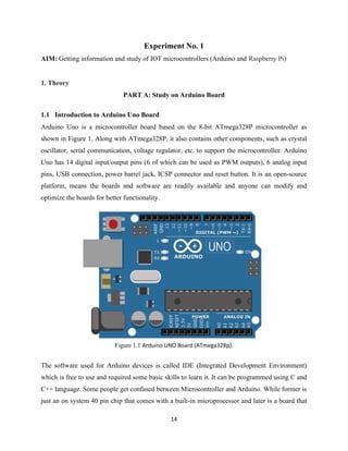
Arduino Uno is a microcontroller board based on the 8-bit ATmega328P microcontroller as
shown in Figure 1. Along with ATmega328P, it also contains other components, such as crystal
oscillator, serial communication, voltage regulator, etc. to support the microcontroller. Arduino
Uno has 14 digital input/output pins (6 of which can be used as PWM outputs), 6 analog input
pins, USB connection, power barrel jack, ICSP connector and reset button. It is an open-source
platform, means the boards and software are readily available and anyone can modify and
optimize the boards for better functionality.
Figure 1.1 Arduino UNO Board (ATmega328p).
The software used for Arduino devices is called IDE (Integrated Development Environment)
which is free to use and required some basic skills to learn it. It can be programmed using C and
C++ language. Some people get confused between Microcontroller and Arduino. While former is
just an on system 40 pin chip that comes with a built-in microprocessor and later is a board that
2. 15
comes with the microcontroller in the base of the board, bootloader and allows easy access to
input-output pins and makes uploading or burning of the program very easy.
1.2 The pin category, pin names and its functionality in detail.
Table 1.1 shows the pin category, pin names and its functionality in detail.
Pin Category Pin Name Details
I. Power Vin, 3.3V, 5V,
GND
Vin: Input voltage to Arduino when using
an external power source.
5V: Regulated power supply used to power
microcontroller and other components on
the board.
3.3V: 3.3V supply generated by on-board
voltage regulator. Maximum current draw is
50mA.
GND: ground pins.
ii Reset Reset Resets the microcontroller.
iii Analog Pins A0 – A5 Used to provide analog input in the range of
0-5V
iv Input/Output
Pins
Digital Pins 0 - 13 Can be used as input or output pins.
v Serial 0(Rx), 1(Tx) Used to receive and transmit TTL serial
data.
vi External
Interrupts
2, 3 To trigger an interrupt.
vii PWM 3, 5, 6, 9, 11 Provides 8-bit PWM output.
viii SPI 10 (SS), 11
(MOSI), 12
(MISO) and 13
(SCK)
Used for SPI communication.
ix Inbuilt LED 13 To turn on the inbuilt LED.
x TWI A4 (SDA), A5
(SCA)
Used for TWI communication.
xi AREF AREF To provide reference voltage for input
voltage.
1.3 Technical Specifications of Arduino Uno Board
Table 1.2 :Technical Specifications of Arduino Uno Board
S. NO Components Specifications
i Microcontroller ATmega328P – 8 bit AVR family
microcontroller
ii Operating Voltage 5V
3. 16
iii Recommended Input Voltage 7-12V
iv Input Voltage Limits 6-20V
v Analog Input Pins 6 (A0 – A5)
vi Digital I/O Pins 14 (Out of which 6 provide PWM
output)
vii DC Current on I/O Pins 40 mA
viii DC Current on 3.3V Pin 50 mA
ix Flash Memory 32 KB (0.5 KB is used for Bootloader)
x SRAM 2 KB
xi EEPROM 1 KB
xii Frequency (Clock Speed) 16 MHz
1.4 Arduino Uno to ATmega328 Pin Mapping
When ATmega328 chip is used in place of Arduino Uno, or vice versa, the image below
shows the pin mapping between the two.
Figure 1.2 ATmega328 Pin Mapping
4. 17
1.5 How to use Arduino Board
1.5.1 Digital Pins
The 14 digital input/output pins can be used as input or output pins by using pinMode(),
digitalRead() and digitalWrite() functions in arduino programming. Each pin operates at 5V and
can provide or receive a maximum of 40mA current, and has an internal pull-up resistor of 20-50
KOhms which are disconnected by default. Out of these 14 pins, some pins have specific
functions as listed below:
1. Serial: 0 (RX) and 1 (TX). Used to receive (RX) and transmit (TX) TTL serial data. On
the Arduino Diecimila, these pins are connected to the corresponding pins of the FTDI USB-
to-TTL Serial chip. On the Arduino BT, they are connected to the corresponding pins of
the WT11 Bluetooth module. On the Arduino Mini and LilyPad Arduino, they are intended for
use with an external TTL serial module (e.g. the Mini-USB Adapter).
2. External Interrupts: 2 and 3. These pins can be configured to trigger an interrupt on a
low value, a rising or falling edge, or a change in value. See the attachInterrupt() function for
details.
3. PWM: 3, 5, 6, 9, 10, and 11. provide 8-bit PWM output with the analogWrite() function.
On boards with an ATmega8, PWM output is available only on pins 9, 10, and 11.
4. BT Reset: 7. (Arduino BT-only) Connected to the reset line of the Bluetooth module.
5. SPI: 10 (SS), 11 (MOSI), 12 (MISO), 13 (SCK). These pins support SPI communication,
which, although provided by the underlying hardware, is not currently included in the
Arduino language.
6. LED: 13. On the Diecimila and LilyPad, there is a built-in LED connected to digital pin 13.
When the pin is HIGH value, the LED is on, when the pin is LOW, it's off.
1.5.2 Analog Pins
In addition to the specific functions listed below, the analog input pins support 10-bit analog-to-
digital conversion (ADC) using the analogRead() function. Most of the analog inputs can also be
5. 18
used as digital pins: analog input 0 as digital pin 14 through analog input 5 as digital pin 19.
Analog inputs 6 and 7 (present on the Mini and BT) cannot be used as digital pins.
I2C: 4 (SDA) and 5 (SCL). Support I2
C (TWI) communication using the Wire
library (documentation on the Wiring website).
1.5.3 Power Pins
VIN (sometimes labelled "9V"). The input voltage to the Arduino board when it's using
an external power source (as opposed to 5 volts from the USB connection or other
regulated power source). You can supply voltage through this pin, or, if supplying
voltage via the power jack, access it through this pin. Note that different boards accept
different input voltages ranges, please see the documentation for your board. Also note
that the LilyPad has no VIN pin and accepts only a regulated input.
5V. The regulated power supply used to power the microcontroller and other components
on the board. This can come either from VIN via an on-board regulator, or be supplied by
USB or another regulated 5V supply.
3V3. (Diecimila-only) A 3.3 volt supply generated by the on-board FTDI chip.
GND. Ground pins.
1.5.4 Other Pins
1. AREF. Reference voltage for the analog inputs. Used with analogReference().
2. Reset. (Diecimila-only) Bring this line LOW to reset the microcontroller. Typically used
to add a reset button to shields which block the one on the board.
1.6 Architecture and basic working of CPU of ATmega328
1. The data is uploaded in serial via the port (being uploaded from the computer’s
Arduino IDE). The data is decoded and then the instructions are sent to instruction
register and it decodes the instructions on the same clock pulse.
6. 19
2. On the next clock pulse the next set of instructions are loaded in instruction register.
3. In general purpose registers the registers are of 8-bit but there are 3 16-bit registers also.
i) 8-bit registers are used to store data for normal calculations and results.
ii) 16-bit registers are used to store data of timer counter in 2 different register. Eg. X-
low & X-high. They are fast, and are used to store specific hardware functions
Figure 1.3 Architecture of Arduino Uno (ATmega328 IC)
4. EEPROM stores data permanently even if the power is cut out. Programming inside a
EEPROM is slow.
5. Interrupt Unit checks whether there is an interrupt for the execution of instruction to be
executed in ISR (Interrupt Service Routine).
7. 20
6. Serial Peripheral Interface (SPI) is an interface bus commonly used to send data between
microcontrollers and small peripherals such as Camera, Display, SD cards, etc. It uses
separate clock and data lines, along with a select line to choose the device you wish to talk to.
7.Watchdog timer is used to detect and recover from MCU malfunctioning.
8. Analog comparator compares the input values on the positive and negative pin, when the
value of positive pin is higher the output is set.
9. Status and control is used to control the flow of execution of commands by checking other
blocks inside the CPU at regular intervals
10. ALU (Arithmetic and Logical unit)The high performance AVR ALU operates in direct
connection with all the 32 general purpose working registers. Within a single clock cycle,
arithmetic operations b/w general purpose registers are executed. The ALU operations are
divided into 3 main categories – arithmetic, logical and bit-function.
11. I/O pins The digital inputs and outputs (digital I/O) on the Arduino are what allow you to
connect the Arduino sensors, actuators, and other ICs. Learning how to use them will allow
you to use the Arduino to do some really useful things, such as reading switch inputs, lighting
indicators, and controlling relay outputs.
1.7 Communication in Arduino board
Arduino can be used to communicate with a computer, another Arduino board or other
microcontrollers. The ATmega328P microcontroller provides UART TTL (5V) serial
communication which can be done using digital pin 0 (Rx) and digital pin 1 (Tx). An
ATmega16U2 on the board channels this serial communication over USB and appears as a
virtual com port to software on the computer. The ATmega16U2 firmware uses the standard
USB COM drivers, and no external driver is needed. However, on Windows, a .inf file is
required. The Arduino software includes a serial monitor which allows simple textual data to be
sent to and from the Arduino board. There are two RX and TX LEDs on the arduino board which
will flash when data is being transmitted via the USB-to-serial chip and USB connection to the
computer (not for serial communication on pins 0 and 1). A SoftwareSerial library allows for
serial communication on any of the Uno's digital pins. The ATmega328P also supports I2C
8. 21
(TWI) and SPI communication. The Arduino software includes a Wire library to simplify use of
the I2C bus.
1.8 Software and programing on Arduino board
1.8.1 Software
Arduino IDE (Integrated Development Environment) is required to program the Arduino Uno
board https://www.arduino.cc/en/software.
1.8.2 Programming Arduino
Once arduino IDE is installed on the computer, connect the board with computer using USB
cable. Now open the arduino IDE and choose the correct board by selecting
Tools>Boards>Arduino/Genuino Uno, and choose the correct Port by selecting Tools>Port.
Arduino Uno is programmed using Arduino programming language based on Wiring. To get it
started with Arduino Uno board and blink the built-in LED, load the example code by selecting
Files>Examples>Basics>Blink. Once the example code (also shown below) is loaded into your
IDE, click on the ‘upload’ button given on the top bar. Once the upload is finished, you should
see the Arduino’s built-in LED blinking. Below is the example code for blinking:
// the setup function runs once when you press reset or power the board
void setup() {
// initialize digital pin LED_BUILTIN as an output.
pinMode(LED_BUILTIN, OUTPUT);
}
// the loop function runs over and over again forever
void loop() {
digitalWrite(LED_BUILTIN, HIGH); // turn the LED on (HIGH is the voltage level)
delay(1000); // wait for a second
digitalWrite(LED_BUILTIN, LOW); // turn the LED off by making the voltage LOW
delay(1000); // wait for a second
}
9. 22
1.9 Application on Arduino board
1. Prototyping of Electronics Products and Systems
2. Multiple DIY Projects.
3. Easy to use for beginner level DIYers and makers.
3. Projects requiring Multiple I/O interfaces and communications.
PART B: Study on Raspberry Pi.
2.1 Introduction to Raspberry Pi
Raspberry Pi is a series of small single-board computers developed in the United Kingdom by
the Raspberry Pi Foundation in association with Broadcom. The Raspberry Pi project originally
leaned towards the promotion of teaching basic computer science in schools and in developing
countries. Created by the Raspberry Pi Foundation, the Raspberry Pi is an open-source, Linux
based, credit card sized computer board. The Pi is an exciting and accessible means of improving
computing and programming skills for people of all ages. By connecting to your TV or monitor
and a keyboard, and with the right programming, the Pi can do many things that a desktop
computer can do such as surf the internet and play video. The Pi is also great for those innovative
projects that you want to try out - newer models are ideal for Internet of Things projects due to
their processing power. With Pi 3, Wireless LAN and Bluetooth Low Energy are on-board too.
The original model became more popular than anticipated, selling outside its target market for
uses such as robotics. It is widely used in many areas, such as for weather monitoring because of
its low cost, modularity, and open design. It is typically used by computer and electronic
hobbyists, due to its adoption of HDMI and USB devices.
2.1.1 Generations of Raspberry Pi
Several generations of Raspberry Pis have been released.
1. The first generation (Raspberry Pi Model B) was released in February 2012, followed by
the simpler and cheaper Model A. These first generation boards feature ARM11 processors,
are approximately credit-card sized and represent the standard mainline form-factor.
10. 23
2. The Raspberry Pi 2 was released in February 2015 and initially featured a 900 MHz 32-
bit quad-core ARM Cortex-A7 processor with 1 GiB RAM. Later versions featured a
1.2 GHz 64-bit quad-core ARM Cortex-A53 processor.
3. Raspberry Pi 3 Model B was released in February 2016 with a 1.2 GHz 64-bit quad
core ARM Cortex-A53 processor, on-board 802.11n Wi-Fi, Bluetooth and USB boot
capabilities. On Pi Day 2018, the Raspberry Pi 3 Model B+ was launched with a faster
1.4 GHz processor, a three-times faster gigabit Ethernet (throughput limited to ca.
300 Mbit/s by the internal USB 2.0 connection), and 2.4 / 5 GHz dual-band 802.11ac Wi-Fi
(100 Mbit/s).
4. Raspberry Pi 4 Model B was released in June 2019 with a 1.5 GHz 64-bit quad
core ARM Cortex-A72 processor, on-board 802.11ac Wi-Fi, Bluetooth 5, full gigabit
Ethernet (throughput not limited), two USB 2.0 ports, two USB 3.0 ports, and dual-monitor
support via a pair of micro HDMI (HDMI Type D) ports for up to 4K resolution. The Pi 4 is
also powered via a USB-C port, enabling additional power to be provided to downstream
peripherals, when used with an appropriate PSU.
5. Raspberry Pi 400 was released in November 2020. It features a custom board that is
derived from the existing Raspberry Pi 4, specifically remodelled with a keyboard attached.
A robust cooling solution similar to the one found in a Commodore 64 allows the Raspberry
Pi 400's Broadcom BCM2711C0 processor to be clocked at 1.8 GHz, which is slightly higher
than the Raspberry Pi 4. The keyboard-computer features 4 GiB of LPDDR4 RAM.
6. Raspberry Pi Pico was released in January 2021 with a retail price of $4. It was
Raspberry Pi's first board based upon a single microcontroller chip; the RP2040, which was
designed by Raspberry Pi in the UK. The Pico has 264 KiB of RAM and 2 MiB of flash
memory. It is programmable in MicroPython, Circuit Python, and C.
2.2 The Raspberry Pi 3 Model B
The Raspberry Pi 3 Model B builds upon the features of its predecessors with a new, faster
processor on board to increase its speed. It also features WiFi and Bluetooth Low Energy
11. 24
capabilities to enhance the functionality and the ability to power more powerful devices over the
USB ports.
1. Quad Core 1.2GHz Broadcom BCM2837 64bit CPU,1GB RAM
2. BCM43438 WiFi and Bluetooth Low Energy (BLE) on board
3. 40-pin Extended GPIO
4. 4x USB 2 ports
5. 4 Pole stereo output and composite video port, Full size HDMI
6. CSI camera port for connecting a Raspberry Pi camera
7. DSI display port for connecting a Raspberry Pi touchscreen display
8. Micro SD port for loading your operating system and storing data
9. Upgraded switched Micro USB power source up to 2.5A.
2.3 The IC of Raspberry Pi 3 Model B
Figure 1.4 Raspberry Pi 3 Model B
12. 25
Figure 1.5 Raspberry Pi 3 Model B-Pin configuration
2.3.1 Raspberry Pi 3 pin names and its functionality in detail.
Table 1.3 shows the pin category of Raspberry Pi 3 pin names and its functionality in detail.
PIN GROUP PIN NAME DESCRIPTION
POWER SOURCE +5V, +3.3V, GND and Vin +5V -power output
+3.3V -power output
GND – GROUND pin
COMMUNICATION
INTERFACE
UART Interface(RXD,
TXD) [(GPIO15,GPIO14)]
UART (Universal Asynchronous
Receiver Transmitter) used for
interfacing sensors and other
devices.
SPI Interface (MOSI, MISO, CLK, CE) x 2
[SPI0-(GPIO10, GPIO9, GPIO11,
GPIO8)]
[SPI1--(GPIO20,GPIO19,
GPIO21, GPIO7)]
SPI (Serial Peripheral Interface)
used for communicating with
other boards or peripherals.
TWI Interface (SDA, SCL) x 2 [(GPIO2,
GPIO3)]
[(ID_SD,ID_SC)]
TWI (Two Wire Interface)
Interface can be used to connect
peripherals.
INPUT OUTPUT PINS 26 I/O Although these some pins have
multiple functions they can be
considered as I/O pins.
13. 26
PWM Hardware PWM available on
GPIO12, GPIO13, GPIO18,
GPIO19
These 4 channels can provide
PWM (Pulse Width Modulation)
outputs.
*Software PWM available on all
pins
EXTERNAL
INTERRUPTS
All I/O In the board all I/O pins can be
used as Interrupts.
2.3.2: Technical Specifications Raspberry Pi 3
Table 1.4: shows Technical Specifications Raspberry Pi 3
Name Description
Microprocessor Broadcom BCM2837 64bit Quad Core Processor
Processor Operating
Voltage
3.3V
Raw Voltage input 5V, 2A power source
Maximum current through
each I/O pin
16mA
Maximum total current
drawn from all I/O pins
54mA
Flash Memory (Operating
System)
16Gbytes SSD memory card
Internal RAM 1Gbytes DDR2
Clock Frequency 1.2GHz
GPU Dual Core Video Core IV® Multimedia Co-Processor. Provides
Open GLES 2.0, hardware-accelerated Open VG, and 1080p30
H.264 high- profile decode.
Capable of 1Gpixel/s, 1.5Gtexel/s or 24GFLOPs with texture
filtering and DMA infrastructure.
Ethernet 10/100 Ethernet
Wireless Connectivity BCM43143 (802.11 b/g/n Wireless LAN and Bluetooth 4.1)
Operating Temperature -40ºC to +85ºC
2.3.3: Board Connectors of Raspberry Pi 3
Table 1.5: Board Connectors of Raspberry Pi 3
Name Description
Ethernet Base T Ethernet Socket
USB 2.0 (Four sockets)
Audio Output 3.5mm Jack and HDMI
Video output HDMI
Camera
Connector
15-pin MIPI Camera Serial Interface (CSI-2)
Display Display Serial Interface (DSI) 15 way flat flex cable connector with two data
14. 27
Connector lanes and a clock lane.
Memory Card
Slot
Push/Pull Micro SDIO
2.4 How to Use RASPBERRY PI 3
As mentioned earlier PI is simply a COMPUTER ON A SINGLE BOARD so it cannot be used
like ARDUINO development boards. For the PI to start working we need to first install
OPERATING SYSTEM. This feature is similar to our PC. The PI has dedicated OS for it; any
other OS will not work.
We will discuss the programming of PI in step by step below.
1. Take the 16GB micro SD card and dedicate it specifically for PI OS.
2. Choose and Download OS software. [https://www.raspberrypi.org/downloads/]
(‘NOOBS’ recommended for beginners )
3. Format the SD card and install OS on to the SD memory card using convenient methods.
4. Take the SD card after OS installation and insert it in PI board.
5. Connect monitor, keyboard and mouse
6. Power the board with micro USB connector
7. Once the power is tuned ON the PI will run on the OS installed in the memory card and
will start from boot.
8. Once all drivers are checked the PI will ask for authorization, this is set by default and
can be changed.
9. After authorization you will reach desktop where all application program development
starts.
On the PI you can download application programs required for your use and can directly install
as you do for your PC. After that you can work on developing required program and get the PI
run the developed programs.
2.5 Programming Languages on RASPBERRY PI 3
Python is the recommended programming language — particularly if you are new to
programming or want to refresh your programming knowledge. Scratch is a great interactive
programming language for children who want to learn to code through creating games, stories
and animations. Other programming languages you can get on your Pi include C, C++, Java and
Ruby.
15. 28
2.6 Application on RASPBERRY PI 3
1. Hobby projects.
2. Low cost PC/tablet/laptop
3. IoT applications
4. Media center
5. Robotics
6. Industrial/Home automation
7. Server/cloud server
8. Print server
9. Security monitoring
10. Web camera
11. Gaming
12. Wireless access point
13. Environmental sensing/monitoring (e.g. WEATHER STATION)
2.7 Detailed description of components:
2.7.1 System Timer: The System Timer peripheral provides four 32-bit timer channels and a
single 64-bit free running counter. Each channel has an output compare register, which is
compared against the 32 least significant bits of the free running counter values.
2.7.2 The Processor: At the heart of the Raspberry Pi is the same processor you would have
found in the iPhone 3G and the Kindle 2, so you can think of the capabilities of the Raspberry Pi
as comparable to those powerful little devices. This chip is a 32 bit, 700 MHz System on a Chip,
which is built on the ARM11 architecture. ARM chips come in a variety of architectures with
different cores configured to provide different capabilities at different price points. The Model B
has 512MB of RAM and the Model A has 256 MB. (The first batch of Model Bs had only
256MB of RAM.).
2.7.3 Interrupt controller: The interrupt controller can be programmed to interrupt the
processor when any of the status bits are set. The GPIO peripheral has three dedicated interrupt
lines. Each GPIO bank can generate an independent interrupt. The third line generates a single
interrupt whenever any bit is set.
2.7.4 General Purpose Input/Output (GPIO): 3.3 volt logic via 26 pin header (NOT 5 volt or
short tolerant) Pins can be configured to be input/output. General Purpose Input/Output (GPIO)
is a generic pin on a chip whose behavior can be controlled by the user at run time. True GPIO
16. 29
(General Purpose Input Output) pins that you can use to turn LEDs on and off etc. I2C interface
pins that allow you to connect hardware modules with just two control pins. SPI interface with
SPI devices, a similar concept to I2C but uses a different standard.
2.7.5 PCM / I2S Audio: The PCM audio interface is an APB peripheral providing input and
output of telephony or high quality serial audio streams. It supports many classic PCM formats
including I2S. The PCM audio interface has 4 interface signals; PCM_CLK - bit clock. PCM_FS
- frame sync signal. PCM_DIN - serial data input. PCM_DOUT - serial data output. PCM is a
serial format with a single bit data_in and out.
2.7.6 DMA Controller: The BCM2835 DMA Controller provides a total of 16 DMA channels.
Each channel operates independently from the others and is internally arbitrated onto one of the
3 system busses.
2.7.7 UART: The BCM2835 device has two UARTS. On mini UART and PL011 UART. The
PL011 UART is a Universal Asynchronous Receiver/Transmitter. This is the ARM UART
(PL011) implementation. The UART performs serial-to-parallel conversion on data characters
received from an external peripheral device or modem, and parallel-to-serial conversion on data
characters received from the Advanced Peripheral Bus (APB).
2.7.8 Pulse Width Modulator: PWM controller incorporates the following features:
1 Two independent output bit-streams, clocked at a fixed frequency.
2 Bit-streams configured individually to output either PWM or a serialized version of a 32-bit
word.
3 PWM outputs have variable input and output resolutions.
4 Serialize mode configured to load data to and/or read data from a FIFO storage block that can
store up to eight 32-bit words.
5 Both modes clocked by clk_pwm which is nominally 100MHz, but can be varied by clock
manager.
2.7.9 CPU
ARM 1176JZF-S (armv6k) 700MHz
RISC Architecture and low power draw.
2.7.10 MEMORY
17. 30
RAM:- 512MB (Model B rev.2), 256 MB (Model A, Model B rev.1)
SD Card:- At least 4GB SD card is needed, and it should be a Class 4 card. Class 4 cards
are capable of transferring at least 4MB/sec. Some of the earlier Raspberry Pi boards had
problems with Class 6 or higher cards, which are capable of faster speeds but are less
stable. One can also use micro SD card using adapter. As there is no hard drive on the Pi;
everything is stored on an SD Card. A protective case is needed as the solder joints on the
SD socket may fail if the SD card is accidentally bent.
2.7.11 Two USB 2.0 ports in RPi: Dual USB sockets on RPi model B, single on model A.It can
be expandable via regular or powered hubs. On the Model B there are two USB 2.0 ports, but
only one on the Model A. Some of the early Raspberry Pi boards were limited in the amount of
current that they could provide. Some USB devices can draw up 500mA. The original Pi board
supported 100mA or so, but the newer revisions are up to the full USB 2.0 spec.
2.7.12 Ethernet port: The model B has a standard RJ45 Ethernet port. The Model A does not,
but can be connected to a wired network by a USB Ethernet adapter (the port on the Model B is
actually an onboard USB to Ethernet adapter). WiFi connectivity via a USB dongle is another
option.
2.7.13 HDMI connector: The HDMI port provides digital video and audio output. 14 different
video resolutions are supported, and the HDMI signal can be converted to DVI (used by many
monitors), composite (analog video signal usually carried over a yellow RCA connector), or
SCART (a European standard for connecting audio-visual equipment) with external adapters.
2.7.14 Video: HDMI or (digital) DVI via cheap adaptor/cable, Composite NTSC/PAL via RCA
,Wide range of resolutions , NO VGA without an add-on, nontrivial converter (Adafruit).
2.7.15 Audio: Via HDMI or from stereo jack , Support Maturity appears to be lagging
2.7.16 Networking : 10/100mbps via RJ45 on model B , Wireless via USB add-on supported.
2.7.17 Power: There is no power switch on the Pi. Micro-USB connector is used to supply
power (this isn‟t an additional USB port; it‟s only for power). Micro-USB was selected because
cheap USB power supplies are easy to find.
18. 31
Primary power via microUSB plug: a 1Amp cell charger works well, but to use a USB hard
drive, 2 Amp power is needed.
2.8 Conclusion: - Target board of such types can be used in low cost system designs using very
less amount of components and can be used for many user defined applications or customizations
2.9 Remarks: - The stiff cables microcontroller on all sides make it hard to keep flat, and some
of the components like the SD card slot can be mechanically damaged even through normal use.
The Pi contains six layers of conductive traces connecting various components, unlike a lot of
simple microcontroller PCBs that just have traces on the top and the bottom. There are four
layers of thin traces sandwiched in between the top and bottom; if the board gets flexed too much
you can break some of those traces in a manner that is impossible to debug
19. 32
Experiment No: 2
Study on IoT Platform
1. Aim: Study of the sensor (IR, temperature, pressure, gas) and the actuator (Piezoelectric
actuator, Pneumatic actuator) using Arduino.
2. Objectives: Understanding the connectivity of Arduino Uno board circuit with IR,
temperature, pressure, gas and Piezoelectric actuator, Pneumatic actuator.
3. Apparatus: IR transmitter & receiver, LM 35 temperature sensor, BMP 280-Atmospheric
Pressure Sensor, Gas sensor MQ 135, Piezoelectric actuator, Pneumatic actuator.
4. Theory:
Sensors: An electronic sensor detects and measures a physical phenomenon, such as
temperature, pressure, force, acceleration and provides corresponding output which is in the form
of an electrical signals.
4.1 IR sensor:
1. An infrared sensor is an electronic instrument which is used to sense certain
characteristics of its surroundings by their emitting and/or detecting infrared radiation.
2. Infrared sensors are also capable of measuring the heat being emitted by an object as well
as detecting the motion.
3. Infrared waves are not visible to the human eye. In the electromagnetic spectrum,
infrared radiation can be found between the visible and microwave regions.
4. The infrared waves typically have wavelengths between 0.75 and 1000 µm.
20. 33
Figure 2.1 IR sensor structure
Figure 2.2 IR sensor functionality
4.2 LM 35 temperature sensor:
1. The LM 35 temperature sensor is a little module that can provide the digital
temperature. It is really easy to set up as one wire is sufficient to control the data
signal.
2. The sensor is frequently used in remote weather stations, home environment control
systems and the controlling the signal can be easily programmable.
21. 34
Figure 2.3 Temperature Sensor
4.3 BMP 280-Atmospheric Pressure Sensor:
1. BMP 280 pressure sensor module is an Arduino compatible tool which is used for
atmospheric pressure measurement in environments. Such measurements mainly allow for
forecasting of short term changes in the weather.
2. The GY-BMP 280 module comes with BMP 280 sensor, which is an environmental sensor
with barometric pressure that is the next generation upgrade to the
BMP085/BMP180/BMP183.
3. The sensor is great for all sorts of weather sensing and can even be used in both type of
serial communication such as 12
C and SPI.
4. The sensor is economic, precision sensing solution for measuring barometric pressure with
± 1hPa absolute accuracy, and temperature with ± 1.0°C accuracy. Pressure changes with
altitude and its measurement can take place with the altimeter with ± 1-meter accuracy.
5. The sensor has pin pitch with 2.54 mm.
Table 2.1 Pin description
Pin No. Pin Name Pin description
1. VCC Power source of 3.3 VDC
2. GND Ground
3. SCL Serial clock
4. SDA Serial Data
22. 35
Figure 2.4 BMP 280 Pressure sensor
Figure 2.5 Interfacing circuit between Arduino and BMP 280 Pressure sensor
Applications:
Enhancement of GPS navigation capability
Indoor navigation such as floor detection, elevator detection can possible
Outdoor navigation such as leisure and sports application takes place
Weather forecast as well as home weather stations
Heath care application such as Sirometry
Vertical velocity indication such as risk/sink speed
Handsets such as mobile phones, tablets PCs, GPS devices
23. 36
Flying toys
Watches
4.4 Gas sensor MQ 135:
MQ-135 gas sensor applies mostly on SnO2 gas which has a lower conductivity in the
clean air as a gas-sensing material.
1. In an atmosphere, there may be polluting gas as well as the conductivity of the gas sensor
raises along with the concentration of the polluting gas increases.
2. MQ-135 performs a good detection in smoke and other harmful gases, especially
sensitive to ammonia, sulfide and benzene steam.
3. It has an ability to detect various harmful gases and MQ-135 is an ideal choice of
different applications of harmful gas detection in a minimal cost.
4. The MQ-135 sensor module comes with a digital pin (fig. 2.6) which makes the sensor to
operate even without a microcontroller. As a result, it is very suitable to detect one
particular gas.
5. The analog pins are required to measure the gases in PPM. The analog pins are basically
TTL driven sensor. It works on + 5 V power supply and as an advantages, it can be used
with most common microcontrollers.
6. The module is powered with 5V and it is important to notice the status of the LED power
module as the LED power will remain turned off meaning the digital output pin will be 0
V as well as gas will not detect.
7. The sensors have to be kept on for pre-heating time before we can actually work with it.
8. Every time, when the sensor gets introduced to this gas at this particular concentration the
digital pin will go high (5 V) else will remain low (0V).
24. 37
Figure 2.6 Gas sensor MQ 135
Applications:
The module can be applied to detect harmful gases to control pollution in metropolitan cities.
a. Actuators:
Actuators convert an electrical signal to the corresponding physical quantity such as
movement, force, sound, display etc. The actuator is a part of any machine which is
responsible for mechanical rotation or controlling. Example: Microphone (coverts sound to
electrical signal), Speaker (converts electrical signal to sound), antenna (converts
electromagnetic energy into electricity and vice versa). The actuators which induce the
movement that can be classified based on their operation, is categorized into three ways,
namely electric, hydraulic and pneumatic actuators. Hydraulic actuators facilitate mechanical
movement with the application of hydraulic power. Pneumatic actuators use compressed air
pressure and electrical actuators use electric power. A sophisticated example of an actuator
that used in the IoT is “digital fingers”. It is used to switch on/off the switches (or anything
that requires a small movement) and can be controlled wirelessly.
i. Piezoelectric actuators:
Piezoelectric actuators are devices that can produce a small displacement with a high
force capability when voltage is applied. There are many applications where a piezoelectric
25. 38
actuator may be used, such as ultra-precise positioning and in the generation and handling of
high forces or pressures in static or dynamic situations. Actuator configuration can vary
frequently which is basically depending on application areas. Piezoelectric stack or
multilayer actuators are manufactured by stacking up piezoelectric disks or plates. The axis
of the stack being the axis of linear motion that occurs when a voltage is applied. Tube
actuators are monolithic devices that contract laterally and longitudinally when a voltage is
applied between the inner and outer electrodes. A disk actuator is a device in the shape of a
planar disk. Ring actuators are also disk actuators with a center bore which make the actuator
axis accessible for optical, mechanical, or electrical purposes. Other less common
configurations include block, disk, bender and bimorph styles. These devices can also be
ultrasonic. Ultrasonic actuators are specifically designed to produce strokes of several
micrometers at ultrasonic (>20 kHz) frequencies. They are especially useful for controlling
vibration, positioning applications, and quick switching. In addition, piezoelectric actuators
can be either direct or amplified. The effect of amplification is not only larger displacement,
but it can also result in slower response times. The critical specifications for piezoelectric
actuators are displacement, force and operating voltage of the actuator. Other factors are
there to consider such as stiffness, resonant frequency, and capacitance. Stiffness is a term
which is used to describe the force required to achieve a certain deformation of a structure.
For piezoelectric actuators, it is the force needed to elongate the device by a certain amount
which is normally specified in terms of Newton per micrometer. Resonance is the frequency
at which the actuators respond with maximum output amplitude. The capacitance is a
function of the excitation voltage frequency.
26. 39
Figure 2.7 Interfacing between Piezoelectric actuators and Arduino
ii. Pneumatic actuators:
A pneumatic actuator uses energy that is formed by vacuum or compressed air at high
pressure to convert into either linear or rotary motion. Pneumatic actuators are notable in their
applications such as the opening and closing of valves takes place. For the reason, they hold
value within applications fields where fire or ignition risk possibility takes place. Pneumatic
actuators are also known in the industry by several different monitors including: pneumatic
cylinders, air cylinders and air actuators. Pneumatic rack and pinion actuators are used for valve
controls of water pipes. Pneumatic energy quickly responds for starting and stopping signals.
The power source does not need to be stored in reverse for operation. Pneumatic actuators enable
for large forces to be produced from relatively small pressure changes (i.e., Pneumatic brakes are
very responsive to small changes in pressure applied by the driver). It is responsible for
converting pressure into forces.
As an example, it is used in robotics in the form of sensors that work like human fingers by
using compressed air. Some advantages take place in pneumatic actuators such as cost efficient
and are applied at extreme temperatures such as the place where air is the safer option than
chemicals other than that, low maintenance, highly durable, have a long operational life, and it
has a very quick starting and stopping motion.
27. 40
Figure 2.8 Interfacing between Pneumatic actuators and Arduino
Conclusions
We have accessed the data from sensors and actuators and also have applied on Arduino Uno
board. Further, data is collected, analyzed and visualized of the IR, temperature, pressure, gas
sensors as well as piezoelectric and pneumatic actuators.