Downloaded 5,257 times
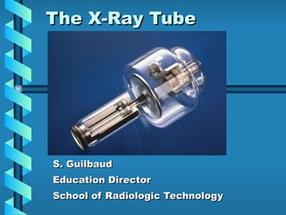


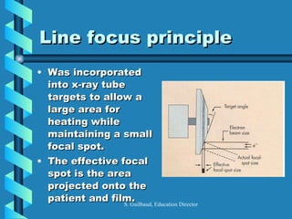

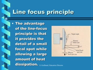

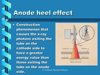

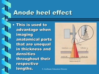

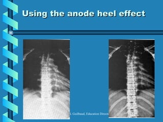


The document discusses the components and functioning of an X-ray tube. The key components are the glass envelope, cathode, and anode. Electrons are emitted from the cathode filament and accelerated toward the anode, where their impact produces X-rays. The rotating anode allows for greater heat dissipation to enable higher exposures. Factors like focal spot size and the anode heel effect determine the quality and characteristics of the emitted X-rays. Proper cooling and protective housing are also important for safe tube operation.


