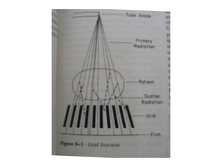
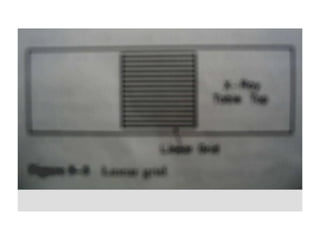
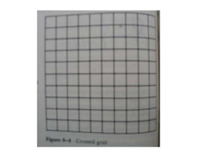
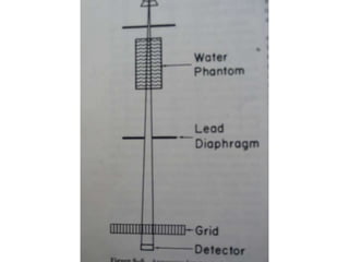
X-RAY GRIDS
Janaramachandran
Devices used to remove scattered
radiation most effectively from a
large radiographic field
Invented by DR.GUSTAVE BUCKY
It consists of series of lead foil
strips separated by
transparent strips.
Interspaces of grids are filled
either with aluminum or some
organic compound .
HOW GRIDWORKS
Primary radiation is oriented in the same axis as
lead strips &passes bt them to reach film
unaffected.scattered radiation arises from many
parts &is multidirectional .
So most of scattered radiation is
absorbed by lead strips &only a
small amount passes bt them.
GRID RATIO
Ratio bt height of lead strips
&distance bt them .
GRID RATIO
r=hD =2.25=8
r=grid ratio
h=height of lead strips .
D=distance bt lead strips .
Grid ratio is are usually expressed
as two numbers,such as 10:1
first no:actual ratio &second
no:always 1.
Ratio ranges from 4:1 to 16:1
Higher the ratio better the grid
function.
Grid pattern refers to orientation
of lead strips in their longitudinal
axis.
Two basics grid patterns are linear
&crossed.
LINEARGRID
lead strips are parallel to
each other in longitudinal
axis.
Adv:is to angle the x-ray tube
along the length of grid with
out loss of primary radiation
from grid cutoff .
Crossed grid –two super imposed
liner grids that have same focusing
distance.
Grid ratio=sum of ratios of two
linear grids.
Crossed grid cannot be used with
oblique technique requiring-
angulation of tube
FOCUSED GRID
Made up of lead strips that are
slightly angulated so that they focus
in space. -
linearcrossed .
Linear focused grid converge at a
line in space cd –convergent line .
Crossed grid converge at a point in
space cd convergent point .
Focal distance is the
perpendicular distance bt grid
&convergent pointline .
Grids have a focusing range –
distance within which grid can
be used without loss of primary
radiation.
Focusing range is fairly wide for a low
grid ratio & narrow for a high grid
ratio .
PARALLEL GRIDS-lead strips are
parallel when viewed in cross
section.
They are focused at infinity&are
used in fluoroscopic spot film .
Lines per inch –no:of lead strips
per inch of grid .
Linesin.=25.4D+d.
D=thickness of interspaces .
d=thickness of lead strips.
Evaluation of grid performance.
Primary transmission.
Bucky factor .
Contrast improvement factor .
PRIMARY TRANSMISSION
-% of primary radiation
transmitted thru a grid .
The x-ray beam is collimated to
a narrow pencil of
radiation,&phantom is placed a
great distance from grid ,no
scatter radiation reaches the
grid.
Two measurements are made -
1,with grid in place to determine
intensity of radiation transmitted
thru grid .
2,after removal of grid to determine
the intensity of radiation directed at
the grid .
Ratio of this gives fractional
transmission ,multiplied by 100gives -
%of transmission.
Tp=IpI`p *100
Tp=primary transmission
Ip=intensity with grid
Ip=intensity with out grid .`
Anticipated primary
transmission .
Primary transmission measured experimentally
is less than anticipated.if there is no grid cutoff
,&no primary radiation is absorbed in
interspaces,then% of grid surface area of
interspaces=%of primary transmission.
Tp=DD+d
Tp=anticipated primary
transmission .
d=thickness of lead strips.
D=thicknessof interspace.
Bucky factor .
Ratio of incident radiation falling on
grid to the transmitted radiation
passing thru grid.
It tells us how much patient`s
exposure is increased by grid.
It measures total quantity of
radiation absorbed from x-ray
beam by grid .
Bucky factor is determined by
large x-ray field&thick phantom .
B=incident radiation transmitted
radiation
Buckyfactor indicates absorption
of primary &secondary radiation.
Higher the bucky factor ,greater
the exposure factor&radiation
dosage to the patient. High ratio
grid absorb more scatter
radiation ,so high bucky factor .
Contrast improvement factor .
Ratio of contrast with a grid to
contrast with out a grid.
Ultimate test for grid performance.
It measure grids ability to improve
contrast .
Contrast improve factor depends
on kVp,field size &phantom
thickness.
Contrast improvement factor is
more closely related to lead
content than any other factor.
Lead content –is expressed in
g/cm2
There is a definite relation bt grid
ratio ,lead content &no:of lines per
inch.
Grid cut off
Loss of primary radiation that occurs
when image of lead strips are projected
wider than they would be with ordinary
magnification.
It is the result of poor geometric
relation bt primary beam &lead
foil strips .
Cutoff is complete &no primary
radiation reaches the film when
projected image of lead strips are
thicker than with of interspaces.
Situation that produce grid cutoff.
1.focused grid used upside down .
2.lateral decentering .
3.focus grid distance decentering .
4.combined lateral &focus –grid
distance decentering .
Upside down focused grid .
There is severe peripheral cut off with
dark band of exposure in center&no
exposure at periphery .higher the grid
ratio-narrower the exposure .when
crossed grid is used a small square in
center is exposed .
Lateral decentering
There is uniform of loss of radiation over the
entire surface producing a uniformly light
radiograph .x-ray tube being positioned
lateral to the convergent line
Factors that affect the magnitude of
cut off from lateral decentering of
film .
1,grid ratio.
2,focal distance .
3,amount of decentering .
Calculation of loss of primary
radiation with lateral decentering.
L=rbf0
L=loss of primary radiation
r=grid ratio
b=lateral decentering distance
fo=focal distance of grid .
Focus grid distance decetering.
Target of x-ray tube is correctly
centered to grid ,but positioned above
or below the convergent line.
If target is above the convergent line –
far focus distance decentering .
If below the convergent line –near
focus grid decentering .
The cutoff is greater with near than
with far focus grid distance
decenterining .the central portion of
film is not affected ,but periphery is
light .
The loss of primary radiation is
directly proportional to the grid
ratio &distance from midline .
Equation for calculating the loss of
primary radiation.
Near focused grid .
L=rc(1f1-1f0)*100
L=loss of primary radiation .
F0=grid focusing distance
f1=target grid distance below the
convergence line.
r=grid ratio
c=distance from center of grid
Far focus grid distance decentering.
L=rc(1f0-1f2) *100
f2=target grid distance above
convergent line .
Parallel grids are focused at
infinity so they are always used
with near focus grid distance
decentering.
Combined lateral&focus –grid
decentering .
Most commonly recognized type of
grid cutoff. Two
types –tube is abovebelow
convergent line.
The amount of cut of is directly
proportional to grid ratio&
decentering distance &inversely
proportional to focal distance of grid
.
Combined decentering is easy to
recognize .
It causes an un even exposure
,resulting in a film that is light on one
side &dark on other side.
With equal decentering error the
amount of cut off is greater with
combined decentering below the
convergent line than with
combined decentering above the
convergent line .
Moving grid
Cd bucky grid .grids are moved to blurred
out the shadow cast by lead strips .most
moving grid continuously move 1to 3cmback
&forth throughtout exposure.
Moving grid eliminate grid lines
from film .
Precaution for avoiding grid lines –
1,grid must move fast enough to
blur its lead strips .if moved slowly
you will see either grid lines
random density variation in film.
Moving grid
2,transverse motion of grid should be
synchronous with the pulses of x-ray
generator ,so that shadow of each
strip is superimposed on the shadow
of neighbor.
Disadvantage of moving grid .
1,cost 2,subject to failure . 3,may vibrate x-
ray tube.4,put limitation on minimum
exposure time bc they move slowly .5,
increase radiation dose to patient.
Increase radiation dose to
patient is due to
1,due to lateral decentering .-
20%reduction in primary radiation
2, photons may spread out uniformly on
the film by a moving grid .
Grid selection
8:1 grid will give adequate result
below 90 kVp.above 90kVp 12:1grid
are preferable.there is little
decrease in transmitted radiation
beyond 8:1grid & no change bt
12:1&16:1,so 12:1is used .
Alternate way of eliminating
scatter radiation with large
radiographic field.intensity of
scatter radiation is max:at patient’s
surface &diminishes at increasing
distance from surface. .
• AIR GAP TEQNIQUES.
Air gap
X-ray exposures are greater &patient
exposures are less bc grid absorbs
some primary radiation.
Thank you.

GRIDS.ppt

  • 1.
  • 2.
    Devices used toremove scattered radiation most effectively from a large radiographic field Invented by DR.GUSTAVE BUCKY
  • 3.
    It consists ofseries of lead foil strips separated by transparent strips. Interspaces of grids are filled either with aluminum or some organic compound .
  • 4.
    HOW GRIDWORKS Primary radiationis oriented in the same axis as lead strips &passes bt them to reach film unaffected.scattered radiation arises from many parts &is multidirectional .
  • 6.
    So most ofscattered radiation is absorbed by lead strips &only a small amount passes bt them.
  • 7.
    GRID RATIO Ratio btheight of lead strips &distance bt them .
  • 9.
    GRID RATIO r=hD =2.25=8 r=gridratio h=height of lead strips . D=distance bt lead strips .
  • 10.
    Grid ratio isare usually expressed as two numbers,such as 10:1 first no:actual ratio &second no:always 1.
  • 11.
    Ratio ranges from4:1 to 16:1 Higher the ratio better the grid function.
  • 12.
    Grid pattern refersto orientation of lead strips in their longitudinal axis. Two basics grid patterns are linear &crossed.
  • 13.
    LINEARGRID lead strips areparallel to each other in longitudinal axis. Adv:is to angle the x-ray tube along the length of grid with out loss of primary radiation from grid cutoff .
  • 15.
    Crossed grid –twosuper imposed liner grids that have same focusing distance. Grid ratio=sum of ratios of two linear grids.
  • 17.
    Crossed grid cannotbe used with oblique technique requiring- angulation of tube
  • 18.
    FOCUSED GRID Made upof lead strips that are slightly angulated so that they focus in space. - linearcrossed .
  • 19.
    Linear focused gridconverge at a line in space cd –convergent line . Crossed grid converge at a point in space cd convergent point .
  • 21.
    Focal distance isthe perpendicular distance bt grid &convergent pointline .
  • 22.
    Grids have afocusing range – distance within which grid can be used without loss of primary radiation. Focusing range is fairly wide for a low grid ratio & narrow for a high grid ratio .
  • 23.
    PARALLEL GRIDS-lead stripsare parallel when viewed in cross section. They are focused at infinity&are used in fluoroscopic spot film .
  • 24.
    Lines per inch–no:of lead strips per inch of grid . Linesin.=25.4D+d. D=thickness of interspaces . d=thickness of lead strips.
  • 25.
    Evaluation of gridperformance. Primary transmission. Bucky factor . Contrast improvement factor .
  • 26.
    PRIMARY TRANSMISSION -% ofprimary radiation transmitted thru a grid .
  • 28.
    The x-ray beamis collimated to a narrow pencil of radiation,&phantom is placed a great distance from grid ,no scatter radiation reaches the grid.
  • 29.
    Two measurements aremade - 1,with grid in place to determine intensity of radiation transmitted thru grid . 2,after removal of grid to determine the intensity of radiation directed at the grid . Ratio of this gives fractional transmission ,multiplied by 100gives - %of transmission.
  • 30.
    Tp=IpI`p *100 Tp=primary transmission Ip=intensitywith grid Ip=intensity with out grid .`
  • 31.
    Anticipated primary transmission . Primarytransmission measured experimentally is less than anticipated.if there is no grid cutoff ,&no primary radiation is absorbed in interspaces,then% of grid surface area of interspaces=%of primary transmission.
  • 32.
    Tp=DD+d Tp=anticipated primary transmission . d=thicknessof lead strips. D=thicknessof interspace.
  • 33.
    Bucky factor . Ratioof incident radiation falling on grid to the transmitted radiation passing thru grid.
  • 34.
    It tells ushow much patient`s exposure is increased by grid. It measures total quantity of radiation absorbed from x-ray beam by grid .
  • 35.
    Bucky factor isdetermined by large x-ray field&thick phantom . B=incident radiation transmitted radiation
  • 36.
    Buckyfactor indicates absorption ofprimary &secondary radiation.
  • 38.
    Higher the buckyfactor ,greater the exposure factor&radiation dosage to the patient. High ratio grid absorb more scatter radiation ,so high bucky factor .
  • 39.
    Contrast improvement factor. Ratio of contrast with a grid to contrast with out a grid.
  • 40.
    Ultimate test forgrid performance. It measure grids ability to improve contrast .
  • 41.
    Contrast improve factordepends on kVp,field size &phantom thickness.
  • 42.
    Contrast improvement factoris more closely related to lead content than any other factor.
  • 43.
    Lead content –isexpressed in g/cm2 There is a definite relation bt grid ratio ,lead content &no:of lines per inch.
  • 44.
    Grid cut off Lossof primary radiation that occurs when image of lead strips are projected wider than they would be with ordinary magnification.
  • 46.
    It is theresult of poor geometric relation bt primary beam &lead foil strips .
  • 47.
    Cutoff is complete&no primary radiation reaches the film when projected image of lead strips are thicker than with of interspaces.
  • 48.
    Situation that producegrid cutoff. 1.focused grid used upside down . 2.lateral decentering . 3.focus grid distance decentering . 4.combined lateral &focus –grid distance decentering .
  • 49.
    Upside down focusedgrid . There is severe peripheral cut off with dark band of exposure in center&no exposure at periphery .higher the grid ratio-narrower the exposure .when crossed grid is used a small square in center is exposed .
  • 51.
    Lateral decentering There isuniform of loss of radiation over the entire surface producing a uniformly light radiograph .x-ray tube being positioned lateral to the convergent line
  • 53.
    Factors that affectthe magnitude of cut off from lateral decentering of film . 1,grid ratio. 2,focal distance . 3,amount of decentering .
  • 54.
    Calculation of lossof primary radiation with lateral decentering. L=rbf0 L=loss of primary radiation r=grid ratio b=lateral decentering distance fo=focal distance of grid .
  • 55.
    Focus grid distancedecetering. Target of x-ray tube is correctly centered to grid ,but positioned above or below the convergent line. If target is above the convergent line – far focus distance decentering . If below the convergent line –near focus grid decentering .
  • 56.
    The cutoff isgreater with near than with far focus grid distance decenterining .the central portion of film is not affected ,but periphery is light .
  • 57.
    The loss ofprimary radiation is directly proportional to the grid ratio &distance from midline .
  • 58.
    Equation for calculatingthe loss of primary radiation. Near focused grid . L=rc(1f1-1f0)*100 L=loss of primary radiation . F0=grid focusing distance f1=target grid distance below the convergence line. r=grid ratio c=distance from center of grid
  • 60.
    Far focus griddistance decentering. L=rc(1f0-1f2) *100 f2=target grid distance above convergent line .
  • 62.
    Parallel grids arefocused at infinity so they are always used with near focus grid distance decentering.
  • 63.
    Combined lateral&focus –grid decentering. Most commonly recognized type of grid cutoff. Two types –tube is abovebelow convergent line. The amount of cut of is directly proportional to grid ratio& decentering distance &inversely proportional to focal distance of grid .
  • 64.
    Combined decentering iseasy to recognize . It causes an un even exposure ,resulting in a film that is light on one side &dark on other side.
  • 67.
    With equal decenteringerror the amount of cut off is greater with combined decentering below the convergent line than with combined decentering above the convergent line .
  • 68.
    Moving grid Cd buckygrid .grids are moved to blurred out the shadow cast by lead strips .most moving grid continuously move 1to 3cmback &forth throughtout exposure.
  • 69.
    Moving grid eliminategrid lines from film . Precaution for avoiding grid lines – 1,grid must move fast enough to blur its lead strips .if moved slowly you will see either grid lines random density variation in film.
  • 70.
    Moving grid 2,transverse motionof grid should be synchronous with the pulses of x-ray generator ,so that shadow of each strip is superimposed on the shadow of neighbor.
  • 71.
    Disadvantage of movinggrid . 1,cost 2,subject to failure . 3,may vibrate x- ray tube.4,put limitation on minimum exposure time bc they move slowly .5, increase radiation dose to patient.
  • 72.
    Increase radiation doseto patient is due to 1,due to lateral decentering .- 20%reduction in primary radiation 2, photons may spread out uniformly on the film by a moving grid .
  • 73.
    Grid selection 8:1 gridwill give adequate result below 90 kVp.above 90kVp 12:1grid are preferable.there is little decrease in transmitted radiation beyond 8:1grid & no change bt 12:1&16:1,so 12:1is used .
  • 74.
    Alternate way ofeliminating scatter radiation with large radiographic field.intensity of scatter radiation is max:at patient’s surface &diminishes at increasing distance from surface. . • AIR GAP TEQNIQUES.
  • 76.
    Air gap X-ray exposuresare greater &patient exposures are less bc grid absorbs some primary radiation.
  • 77.