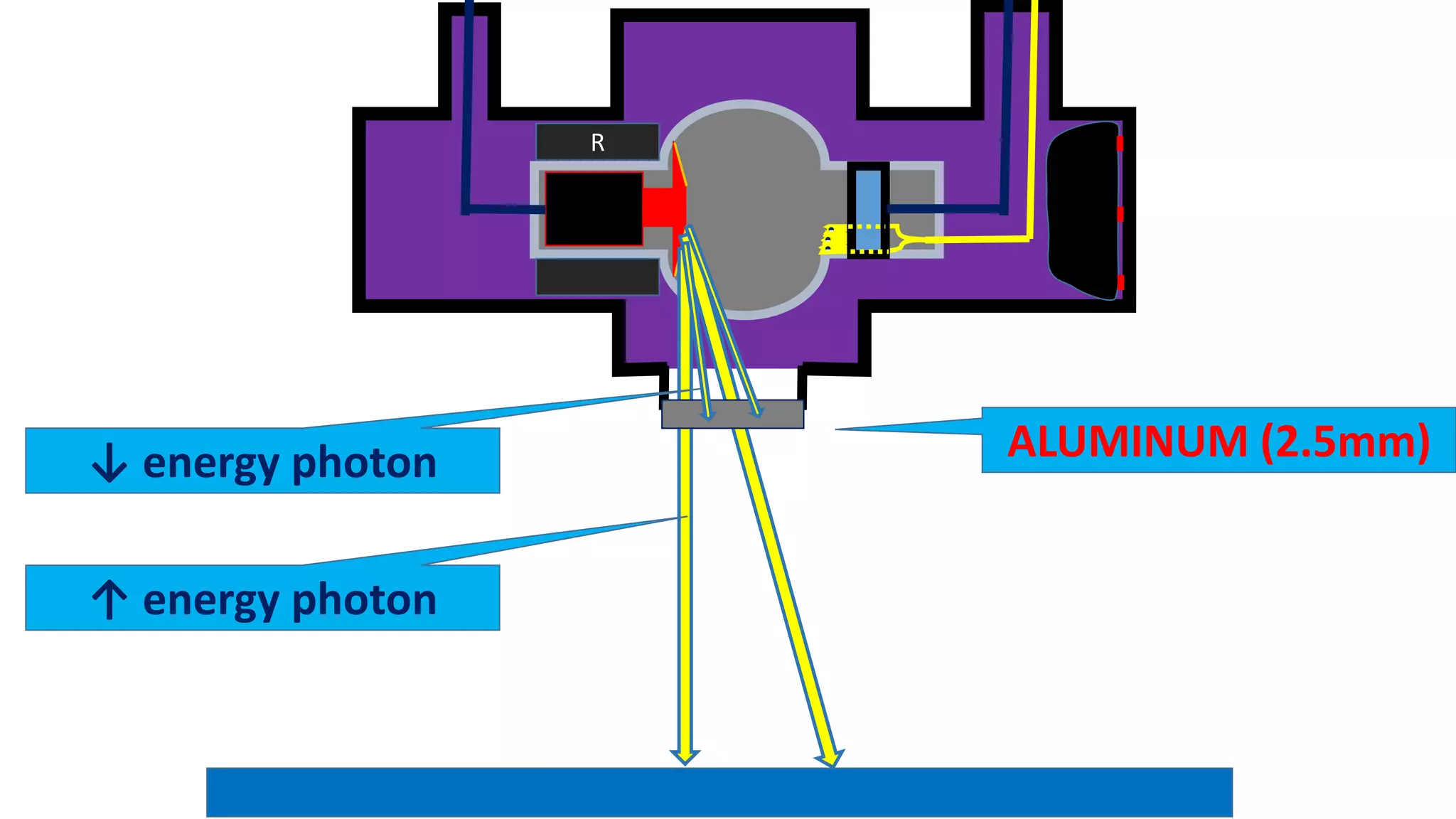
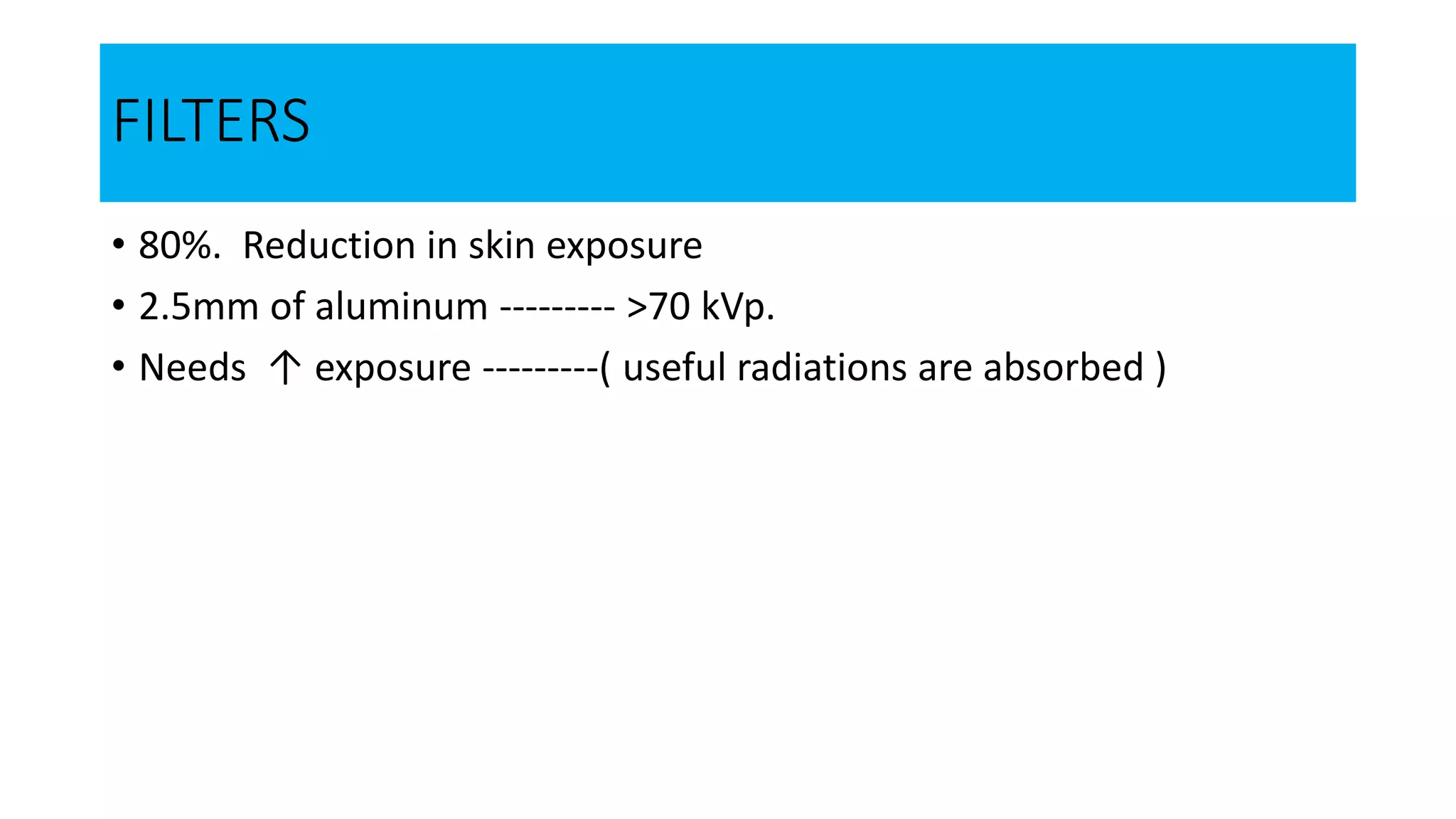
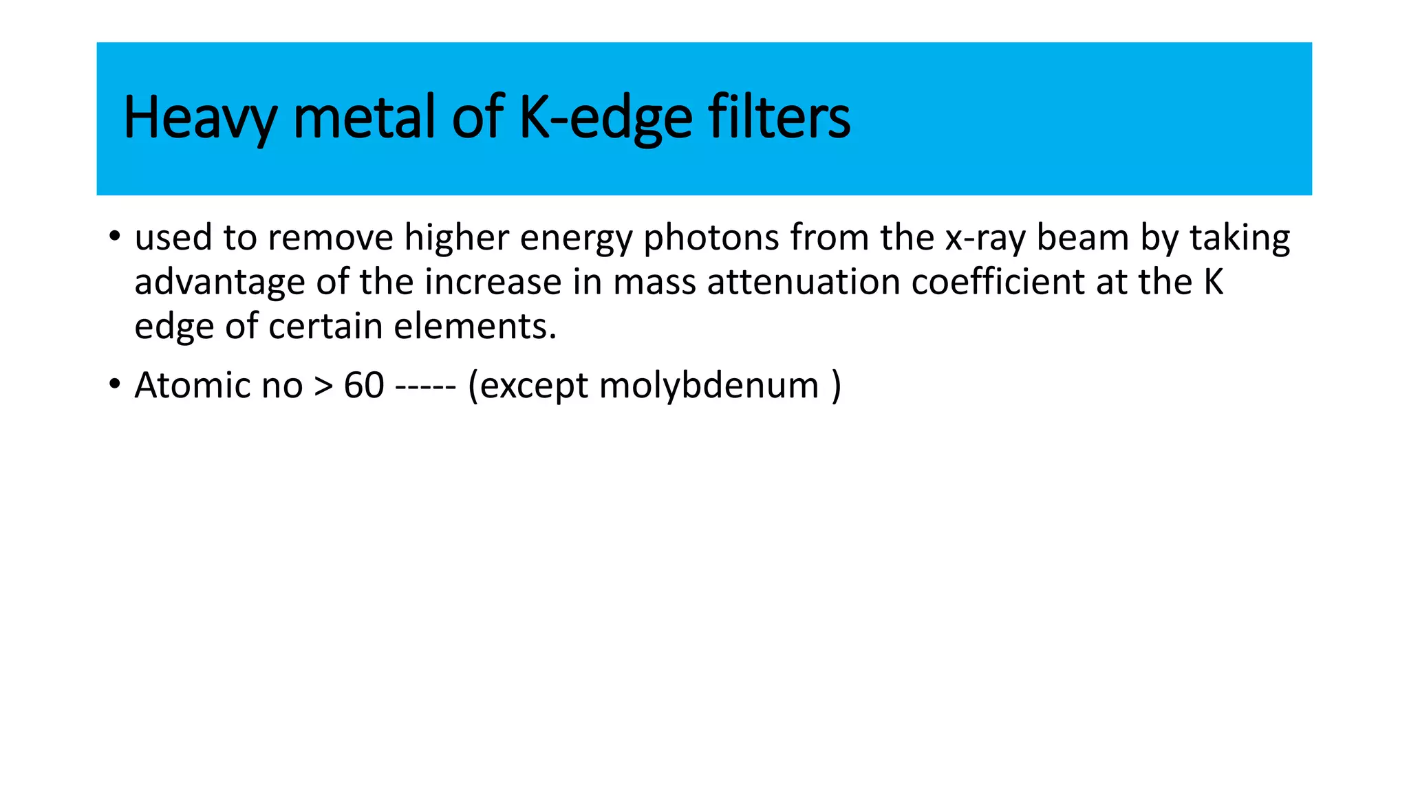
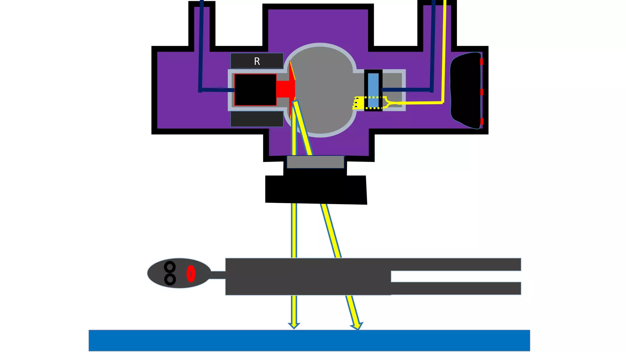
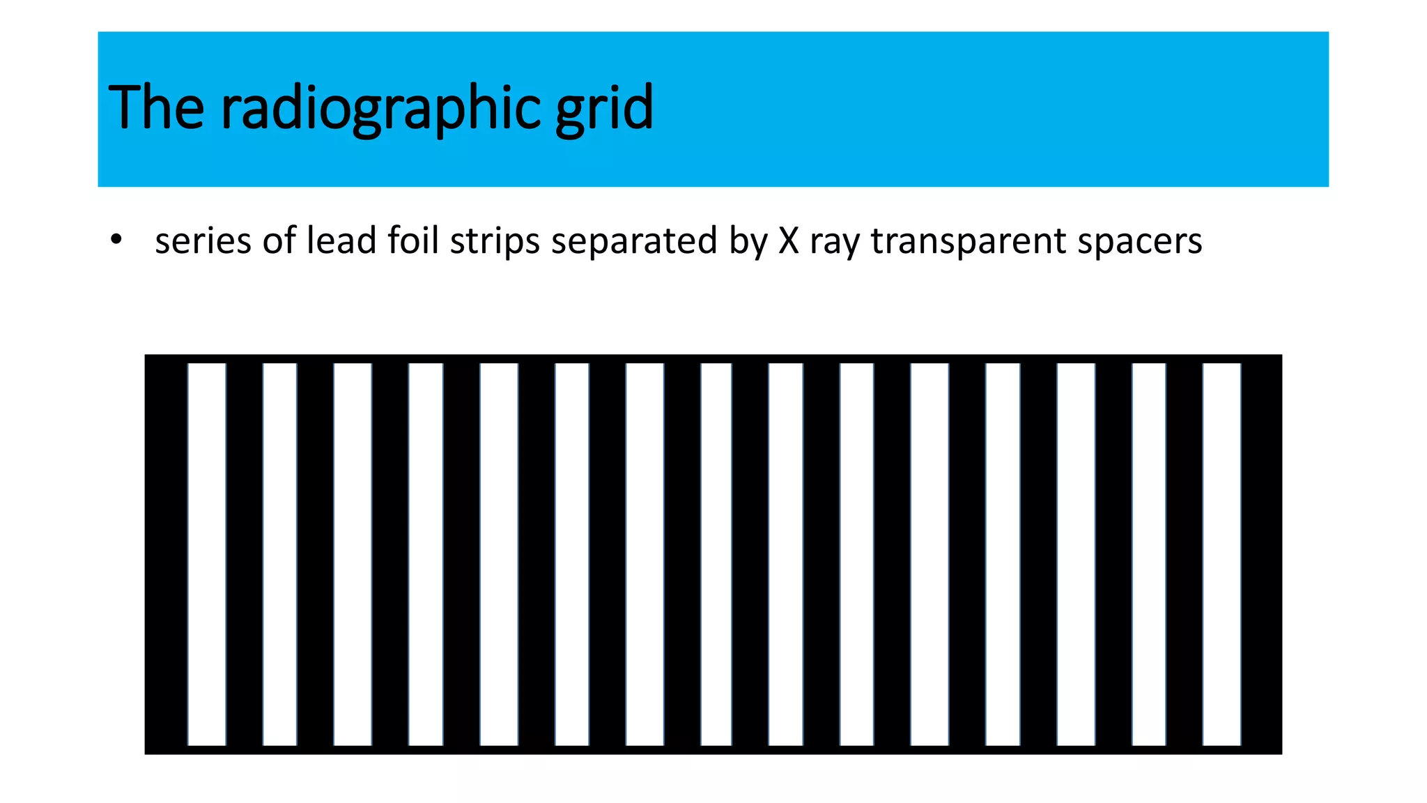
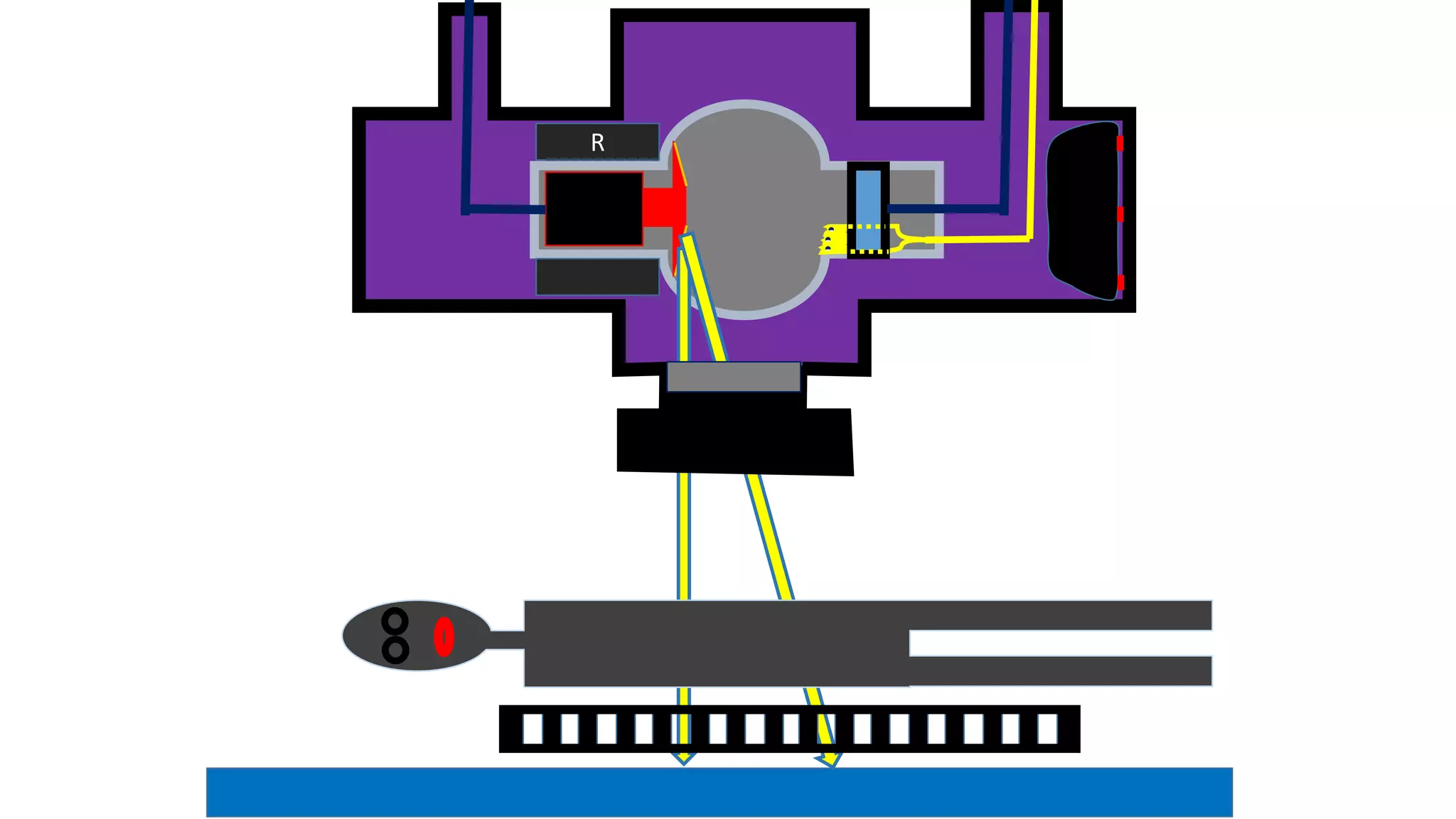
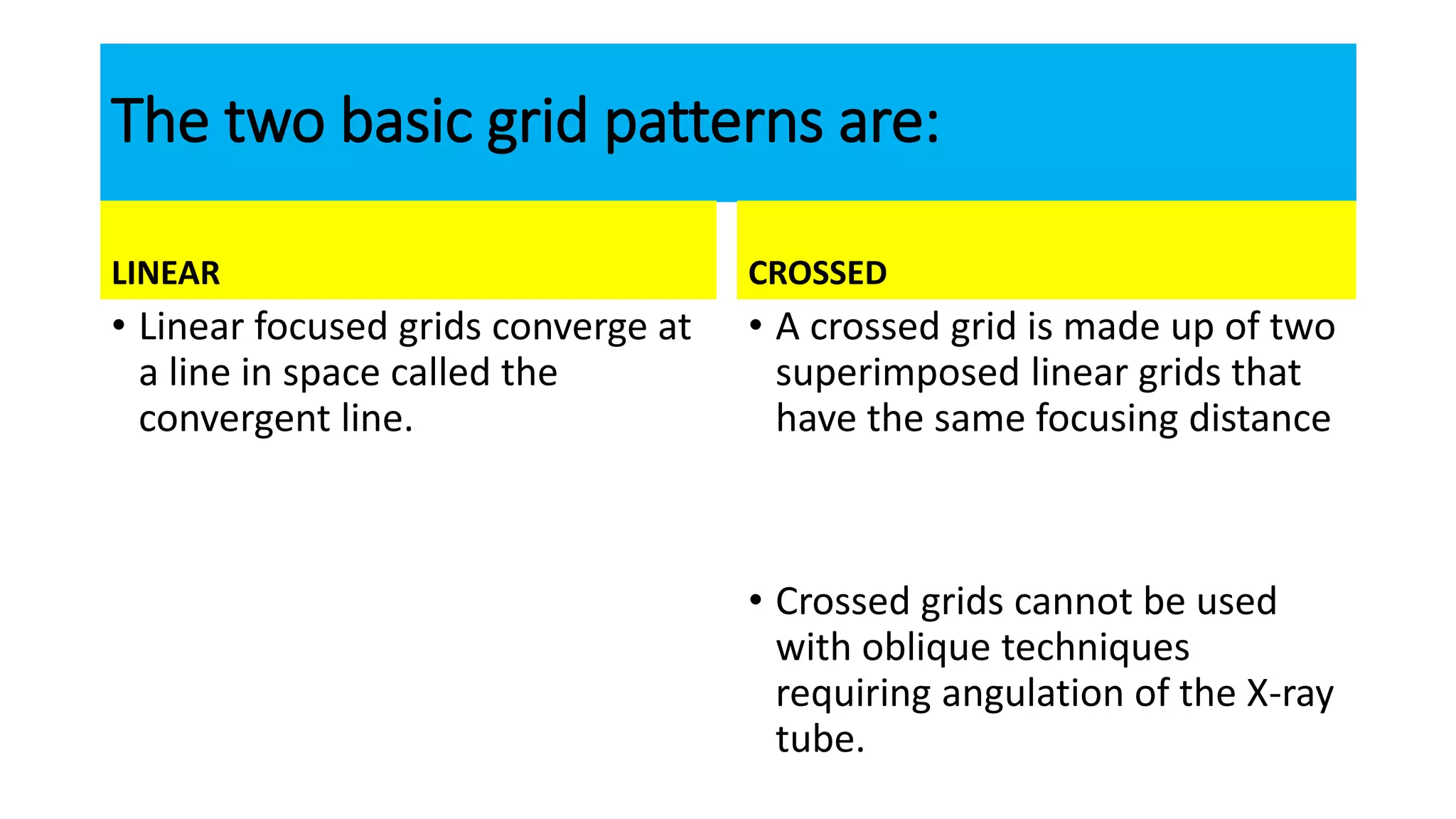
FILTERS
DR PRAJWITH RAI
-
-
-
R
ALUMINUM (2.5mm)↓ energy photon
↑ energy photon
FILTERS
• 80%. Reduction in skin exposure
• 2.5mm of aluminum --------- >70 kVp.
• Needs ↑ exposure ---------( useful radiations are absorbed )
Heavy metal of K-edge filters
• used to remove higher energy photons from the x-ray beam by taking
advantage of the increase in mass attenuation coefficient at the K
edge of certain elements.
• Atomic no > 60 ----- (except molybdenum )
K edge filters advantages
• enhance contrast for iodine and barium,
• reduce patient dose, and
• increase tube loading.
CONES &
COLLIMATORS
-
-
-
R
x-ray beam restrictors
• Aperture diaphragms,
• Cones (cylinders), and
• Collimators.
• REGULATE
• size
• shape of x-ray beam.
x-ray beam restrictors
1. a smaller area of the patient is exposed
2. generate less scatter radiation
• ↓ x-ray field size === exposure factors must be ↑ ===constant film density.
•
Collimators are the best general purpose
beam restrictors
• the x-ray field is illuminated ===accurate localization on the patient;
• x-ray field can be adjusted = ==variety of rectangular shapes and sizes.
•
GRIDS
The radiographic grid
• series of lead foil strips separated by X ray transparent spacers
-
-
-
R
The two basic grid patterns are:
LINEAR
• Linear focused grids converge at
a line in space called the
convergent line.
CROSSED
• A crossed grid is made up of two
superimposed linear grids that
have the same focusing distance
• Crossed grids cannot be used
with oblique techniques
requiring angulation of the X-ray
tube.
The three methods of evaluating grid performance:
1. Primary transmission(Tp)
2. Bucky factor (B)
3. Contrast improvement factor(K)
Primary transmission(Tp)
• % of primary radiation transmitted through the grid.
Bucky factor (B)
• incident radiation falling / transmitted radiation
• It indicates
• how much we must increase exposure factors when we change from a non
grid to a grid technique.
Contrast improvement factor(K)
• contrast with a grid / contrast without a grid.
• grid ratio α contrast improvement factor.
• Is the ultimate test of grid performance
Grid ratio / lead content and / No of lines per inch.
• When grids are constructed with many lines per inch, both the
thickness and height of the lead strips are decreased.
• These grids are thinner, and improve contrast less than grids of
comparable ratios with fewer lines per inch.
GRID CUT OFF
• Grid cut off is the loss of primary radiation that occurs when the
images of the lead strips are projected wider than they would be with
ordinary magnification
• The amount of cutoff is always greatest with
1. high ratio grids and
2. short grid focus distances
LATERAL DECENTERING
• the most common kind of grid cutoff, but it cannot be recognised by
inspection of the film.
• The films become Progressively lighter as the amount of lateral
decentering increases
FOCUS-GRID DISTANCE DECENTERING
• The central portion of the film is not affected, but the periphery is
light.
COMBINED LATERAL &FOCUS-GRID
DISTANCE DECENTERING
• It causes an uneven exposure, resulting in a film that is light on one
side and dark on the other side.
MOVING GRIDS
• Grids are moved to blur out the shadows cast by the lead strips.
• They eliminate grid lines from the film
MOVING GRIDS-DISADVANTAGES
• They are costly
• Subject to failure
• May vibrate the X-ray table
• Put a limit on the minimum exposure time because they move slowly
• increase the patient’s radiation dose
GRID SELECTION
• Usually 8:1 grid will give adequate results below 90kVp.
• Above 90kVp, 12:1 grids are preferred.
AIR GAP TECHNIQUE
• An alternative method of eliminating scattered radiation.
• The film is placed at a distance and the scatter simply misses the film.
• FFD is increased to maintain image sharpness
• Exposure factors are greater with air gaps than with grids

Filters grids and collimators

  • 1.
  • 2.
    - - - R ALUMINUM (2.5mm)↓ energyphoton ↑ energy photon
  • 3.
    FILTERS • 80%. Reductionin skin exposure • 2.5mm of aluminum --------- >70 kVp. • Needs ↑ exposure ---------( useful radiations are absorbed )
  • 4.
    Heavy metal ofK-edge filters • used to remove higher energy photons from the x-ray beam by taking advantage of the increase in mass attenuation coefficient at the K edge of certain elements. • Atomic no > 60 ----- (except molybdenum )
  • 5.
    K edge filtersadvantages • enhance contrast for iodine and barium, • reduce patient dose, and • increase tube loading.
  • 6.
  • 7.
  • 8.
    x-ray beam restrictors •Aperture diaphragms, • Cones (cylinders), and • Collimators. • REGULATE • size • shape of x-ray beam.
  • 9.
    x-ray beam restrictors 1.a smaller area of the patient is exposed 2. generate less scatter radiation • ↓ x-ray field size === exposure factors must be ↑ ===constant film density. •
  • 10.
    Collimators are thebest general purpose beam restrictors • the x-ray field is illuminated ===accurate localization on the patient; • x-ray field can be adjusted = ==variety of rectangular shapes and sizes. •
  • 11.
  • 12.
    The radiographic grid •series of lead foil strips separated by X ray transparent spacers
  • 13.
  • 14.
    The two basicgrid patterns are: LINEAR • Linear focused grids converge at a line in space called the convergent line. CROSSED • A crossed grid is made up of two superimposed linear grids that have the same focusing distance • Crossed grids cannot be used with oblique techniques requiring angulation of the X-ray tube.
  • 15.
    The three methodsof evaluating grid performance: 1. Primary transmission(Tp) 2. Bucky factor (B) 3. Contrast improvement factor(K)
  • 16.
    Primary transmission(Tp) • %of primary radiation transmitted through the grid.
  • 17.
    Bucky factor (B) •incident radiation falling / transmitted radiation • It indicates • how much we must increase exposure factors when we change from a non grid to a grid technique.
  • 18.
    Contrast improvement factor(K) •contrast with a grid / contrast without a grid. • grid ratio α contrast improvement factor. • Is the ultimate test of grid performance
  • 19.
    Grid ratio /lead content and / No of lines per inch. • When grids are constructed with many lines per inch, both the thickness and height of the lead strips are decreased. • These grids are thinner, and improve contrast less than grids of comparable ratios with fewer lines per inch.
  • 20.
    GRID CUT OFF •Grid cut off is the loss of primary radiation that occurs when the images of the lead strips are projected wider than they would be with ordinary magnification • The amount of cutoff is always greatest with 1. high ratio grids and 2. short grid focus distances
  • 21.
    LATERAL DECENTERING • themost common kind of grid cutoff, but it cannot be recognised by inspection of the film. • The films become Progressively lighter as the amount of lateral decentering increases
  • 22.
    FOCUS-GRID DISTANCE DECENTERING •The central portion of the film is not affected, but the periphery is light.
  • 23.
    COMBINED LATERAL &FOCUS-GRID DISTANCEDECENTERING • It causes an uneven exposure, resulting in a film that is light on one side and dark on the other side.
  • 24.
    MOVING GRIDS • Gridsare moved to blur out the shadows cast by the lead strips. • They eliminate grid lines from the film
  • 25.
    MOVING GRIDS-DISADVANTAGES • Theyare costly • Subject to failure • May vibrate the X-ray table • Put a limit on the minimum exposure time because they move slowly • increase the patient’s radiation dose
  • 26.
    GRID SELECTION • Usually8:1 grid will give adequate results below 90kVp. • Above 90kVp, 12:1 grids are preferred.
  • 27.
    AIR GAP TECHNIQUE •An alternative method of eliminating scattered radiation. • The film is placed at a distance and the scatter simply misses the film. • FFD is increased to maintain image sharpness • Exposure factors are greater with air gaps than with grids

Editor's Notes

  • #3 LEAD JACKET EXPANSION BELLOWS
  • #8 LEAD JACKET EXPANSION BELLOWS
  • #14 LEAD JACKET EXPANSION BELLOWS