Call Girls Chandigarh 👙 7001035870 👙 Genuine WhatsApp Number for Real Meet
Grids JP .ppt
1.
2. A device placed between the patient
and film for the purpose of absorbing
scattered radiation before it can
interact with the imaging receptor.
An X-ray grid is the part of an
X-ray machine that filters out
randomly deflected radiation that
can obscure or blur an image produced by the machine.
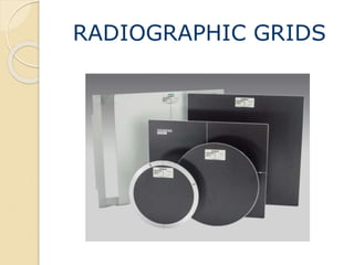
Radiographic Grid
3. Grids are devices that are used to improve contrast on a
radiographic image.
This improvement of contrast is achieved by absorption of
scatter radiation produced by the patient as the primary
beam interacts with the patient’s tissues.
When an X-ray machine sends radiation through an object,
specifically a body, the object absorbs or deflects most of the
rays.
Only about 1 percent of the X-rays pass through the body
on a straight line and burn an image onto the film. The
deflected X-rays can hit the film at random angles, obscuring
the image. The grid filters out these random X-rays.
A high quality grid can attenuate 80 –90 % of scatter
radiation
4.
5. Creating the Image
Transmission
◦ Responsible for dark areas
Absorption
◦ Responsible for light areas
Scatter
◦ Creates fog
◦ Lowers contrast
3 factors contribute to an
increase in scatter
◦ kV increases
◦ Field size increases
◦ Thickness of part increases
6. History
First grid was made by Dr.Gustav Bucky
in 1913.
Consisted of wide strips of lead approx.
2cm apart in a crisscross pattern.
1920 – Dr. Hollis Potter improved the
grid device.
Realigned the lead strips to run in one
direction.
Made the lead strips thinner.
7. Grid Construction
Grid Materials
A series of radiopaque lead strips which
alternate with radiolucent materials.
a. Strips are held firmly together then sliced into flat
sheets.
b. Lead is the radiopaque material of choice.
Interspace materials are radiolucent, made of
a. Aluminum
b. Plastic fibers
X-rays that create the true image on the film travel in a straight line, so
they will pass right through the grid. Deflected X-rays that would add
noise to the image hit the grid strips at an angle and will not hit the film.
8. Aluminium is more common than plastic fiber because of
ease to manufacture, durability and provides additional
absorption of low energy photons.
Disadvantage when using low kVp technics.
Fiber Interspace grids are preferred when using low kVp
technics (pediatric radiography).
Grid Patterns
Criss-cross or cross-hatched
Linear
◦ Parallel
◦ Focused
9. Parallel grids
All lead strips are parallel to one another and straight up
and down
Less commonly employed than focused grids.
Best used with longer SIDs because the beam is
straighter and more perpendicular at longer SIDs.
Lead strips run the length of the cassette.
10. Focused grids
Lead strips are tilted toward the center to correspond with
the divergence of the X-ray beam.
11. Crisscross
Contains two sets of lead strips
at 90 degrees from one
another.
Cross-hatched
Equivalent of two linear grids
not quite at 90 degrees.
12. Grid Selection
Patient Dose
Exam
Detail required
Part thickness
Desired technique (kVp)
Equipment availability
Indications for Grid Use
Part thickness > 10 cm
kVp > 60
13. Grid Dimensions
• h = the height of the
radiopaque strips
• D = the distance between
the strips
– the thickness of the
interspace material
Grid ratio = h/D
The distance between lead strips may remain constant
so the hight of the grid must increase as grid ratios
increase.
High ratio grids usually "clean-up the beam," removing
scatter radiation more effectively than low ratio grids.
14. Grid Ratio
Higher grid ratio
◦ More efficient in removing
scatter
Typical grid ratio range is
5:1 to 16:1
15. Grid Frequency
The number of lead strips
per inch or cm
Frequency range
◦ 60-200 lines/in
◦ 25-80 lines/cm
Typically higher frequency
grids have thinner lead
strips
Higher frequency with the same
interspace distance reduces the
grid effectiveness
16. Grid ratios range from 5:1 to 16:1
Most common 8:1 to 10:1
A 5:1 grid will clean up 85% (Mammography uses 5: 1)
16:1 clean up 97%
17. LIMITATIONS OF GRIDS
The grid can be used for higher exposure data (higher
mAs values and higher kilovolts) is a disadvantage.
For mammography the grids cannot be used since they
use low energy x ray for the imaging process.
Grid Cut - off
It is an undesirable absorption of primary x-ray beams
by grid strips, which prevents the useful x-rays from
reaching the image receptor.
It is caused by improper grid positioning and most
often occurs with parallel grids.
18. Grid cut off - Decrease in density on the film because the grid is absorbing
the primary beam.
Peripheral cut off - Absorption of the primary beam due to the divergence of
the beam at the periphery of a parallel grid.
Off focus grid - Peripheral grid cut off that occurs because the SID is not
within the recommended focal range. Higher grid ratios have narrower focal
ranges.
Off level grid - A decrease in density across the film that occurs when the grid
or tube is angled.
Off center grid - Decreased density across the film caused by incorrect
centering. The center of the grid must be positioned directly under the x-ray
tube target. Correct centering is more important with higher grid ratios.
Upside down grid - Severe cut off on either side of the central ray and
increased density in the middle of the film caused by placing a focused grid
in upside down.
TYPES
19. The air gap technique is an old method for the rejection of
scattered radiation. It is still used in lung examinations.
The air gap technique is a radiographic technique that improves
image contrast resolution by reducing the amount of scattered
radiation that reaches the image receptor.
In the air gap technique, the object-to-image distance (OID) is
increased, resulting in a magnified image. To reduce magnification,
source-to-image distance (SID) can be increased.
Air Gap Technique
20. The disadvantage of the grid-air gap technique is an increased
patient skin dose because of the short focal spot-object
distance.