Downloaded 143 times
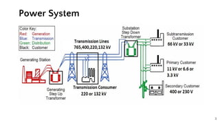
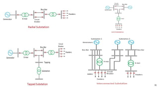
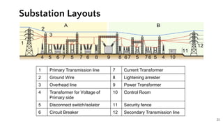
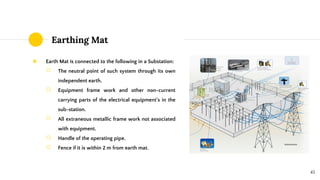
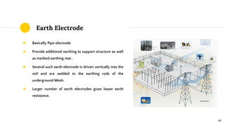
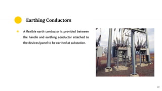
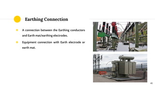

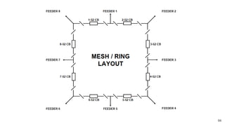
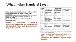
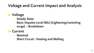


The document provides an overview of substations, including their functions, types, and equipment. Key considerations such as load growth, reliability, and technical specifications are discussed, along with different substation types like transformer, switching, and industrial substations. It also covers important aspects of substation design and layout, earthing systems, and bus switching schemes for operational effectiveness.


