Downloaded 168 times


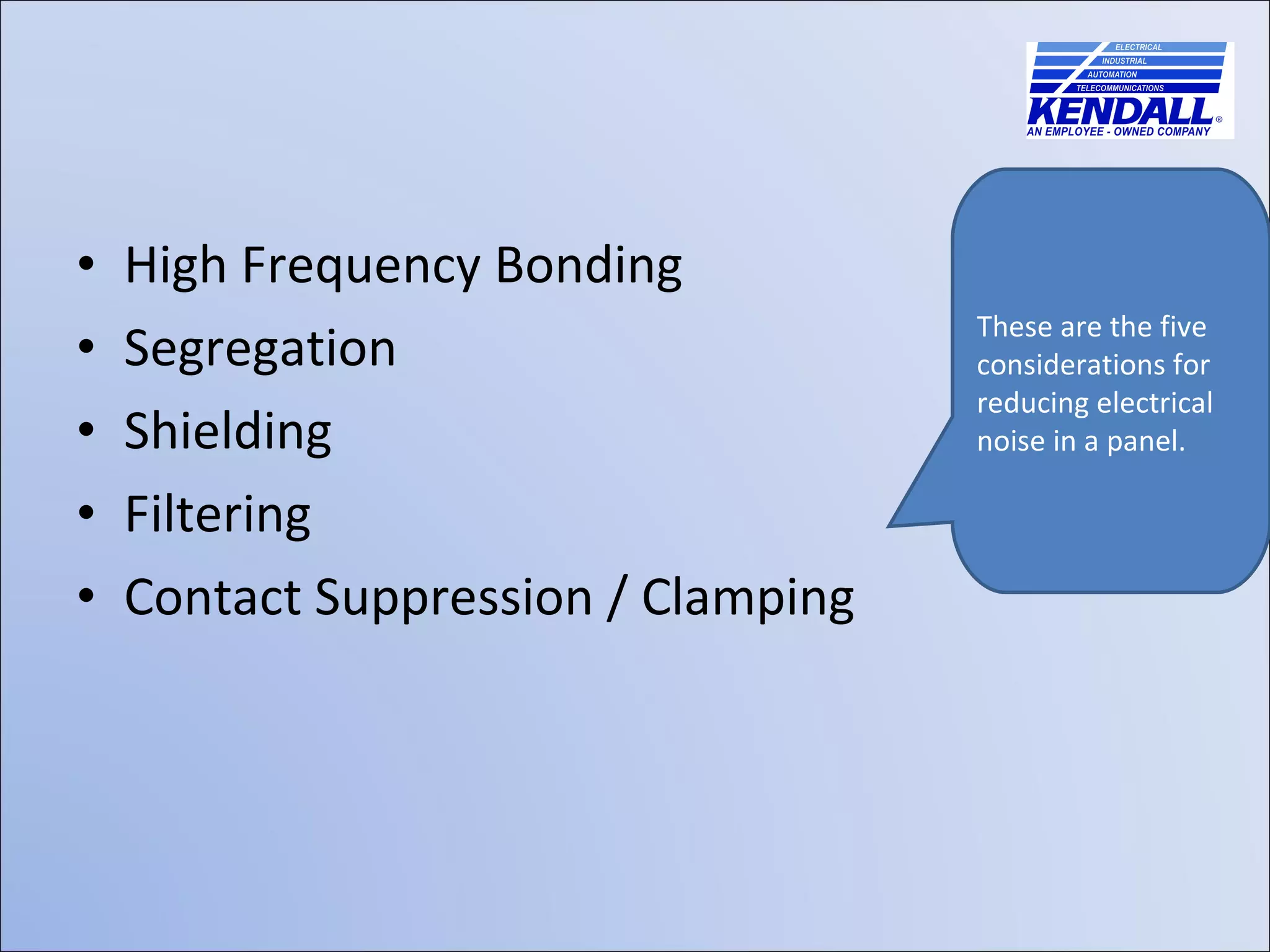
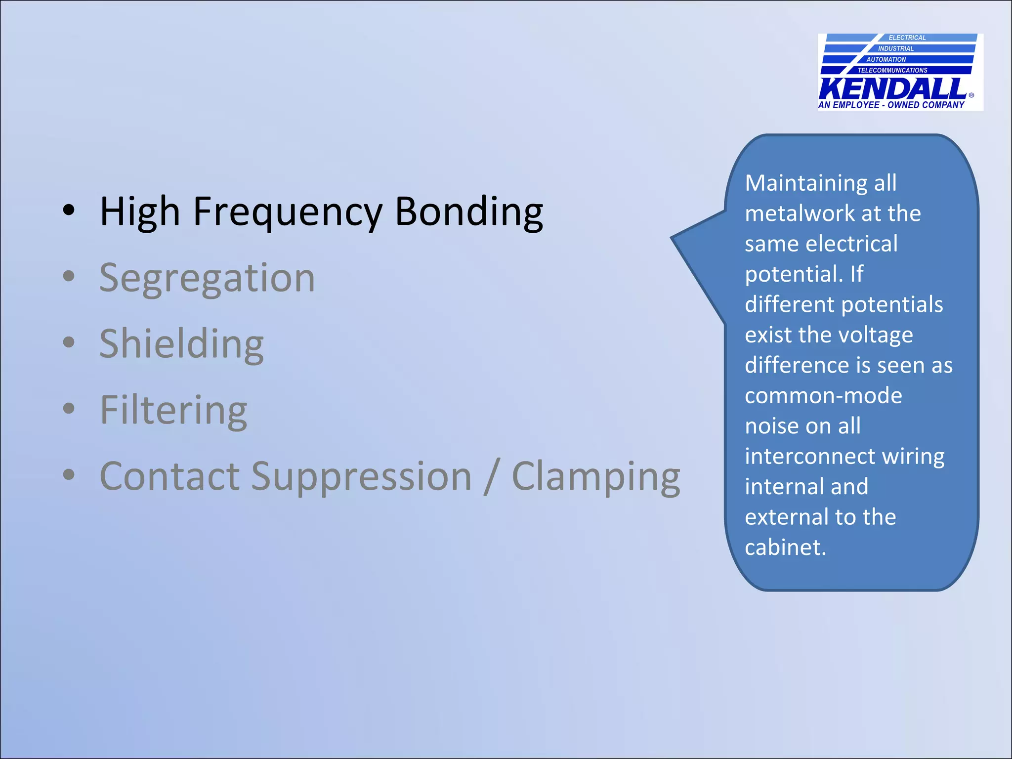
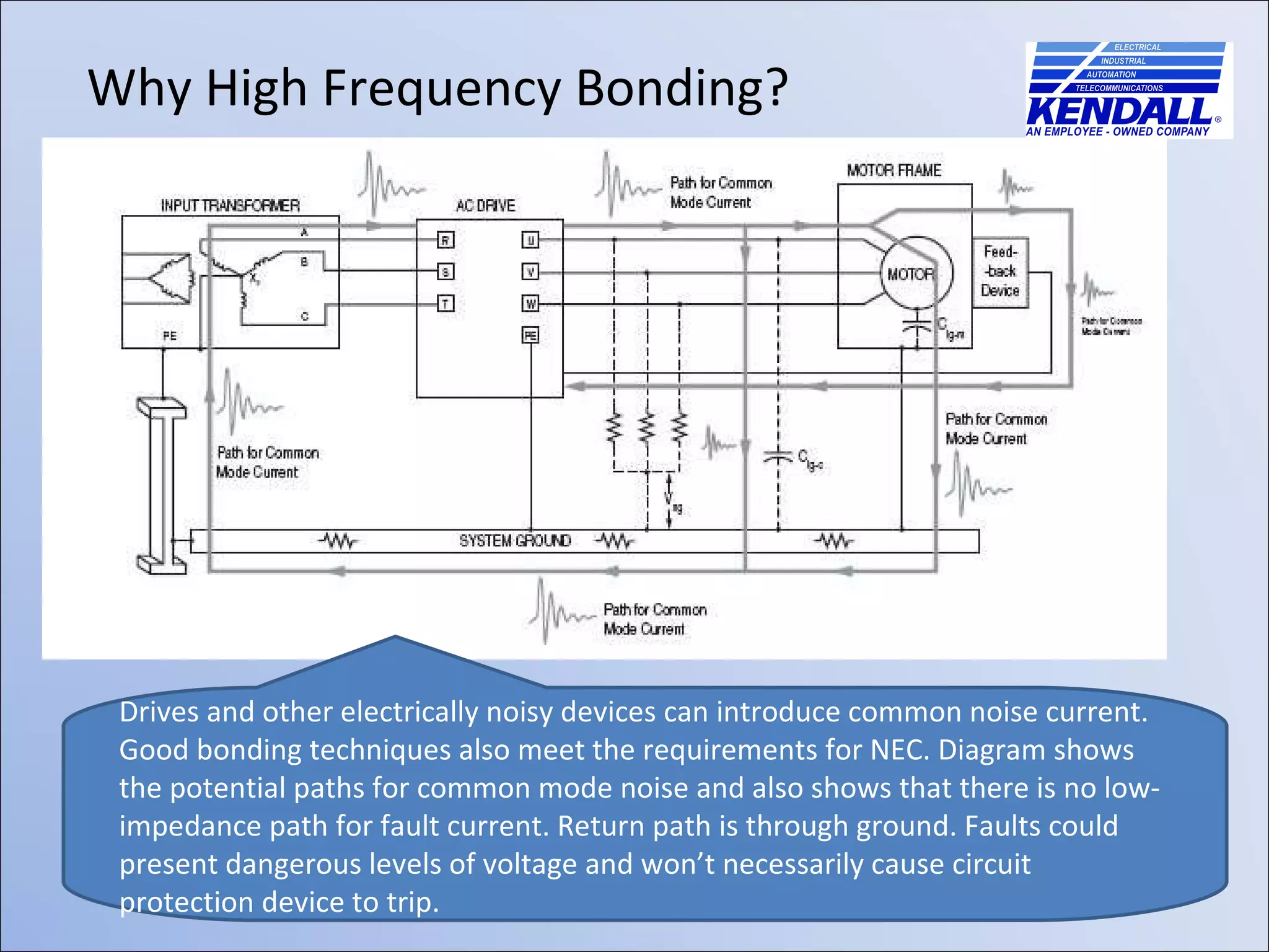
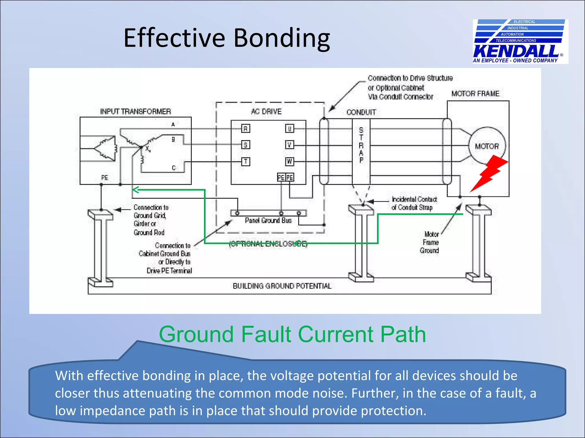

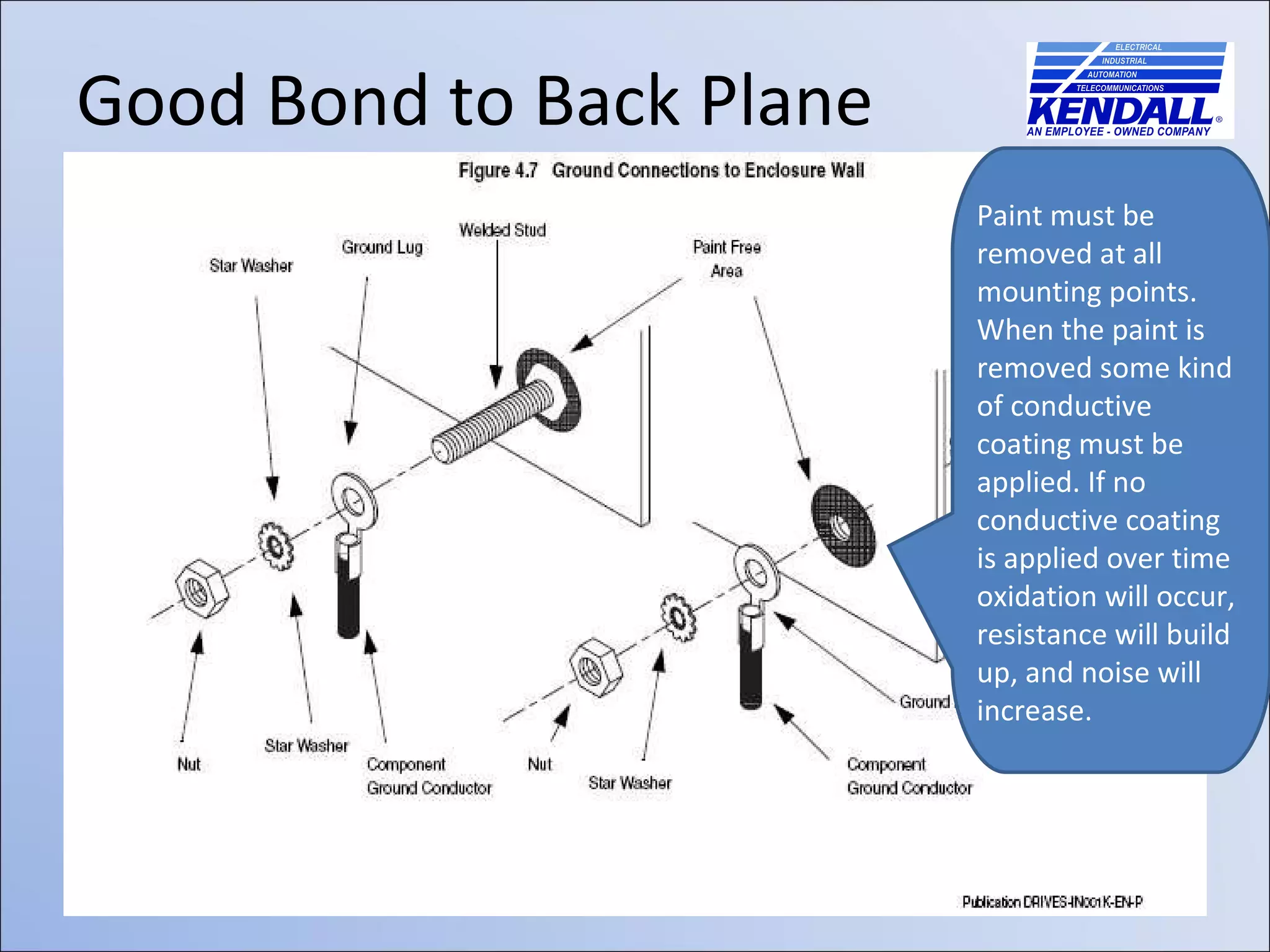
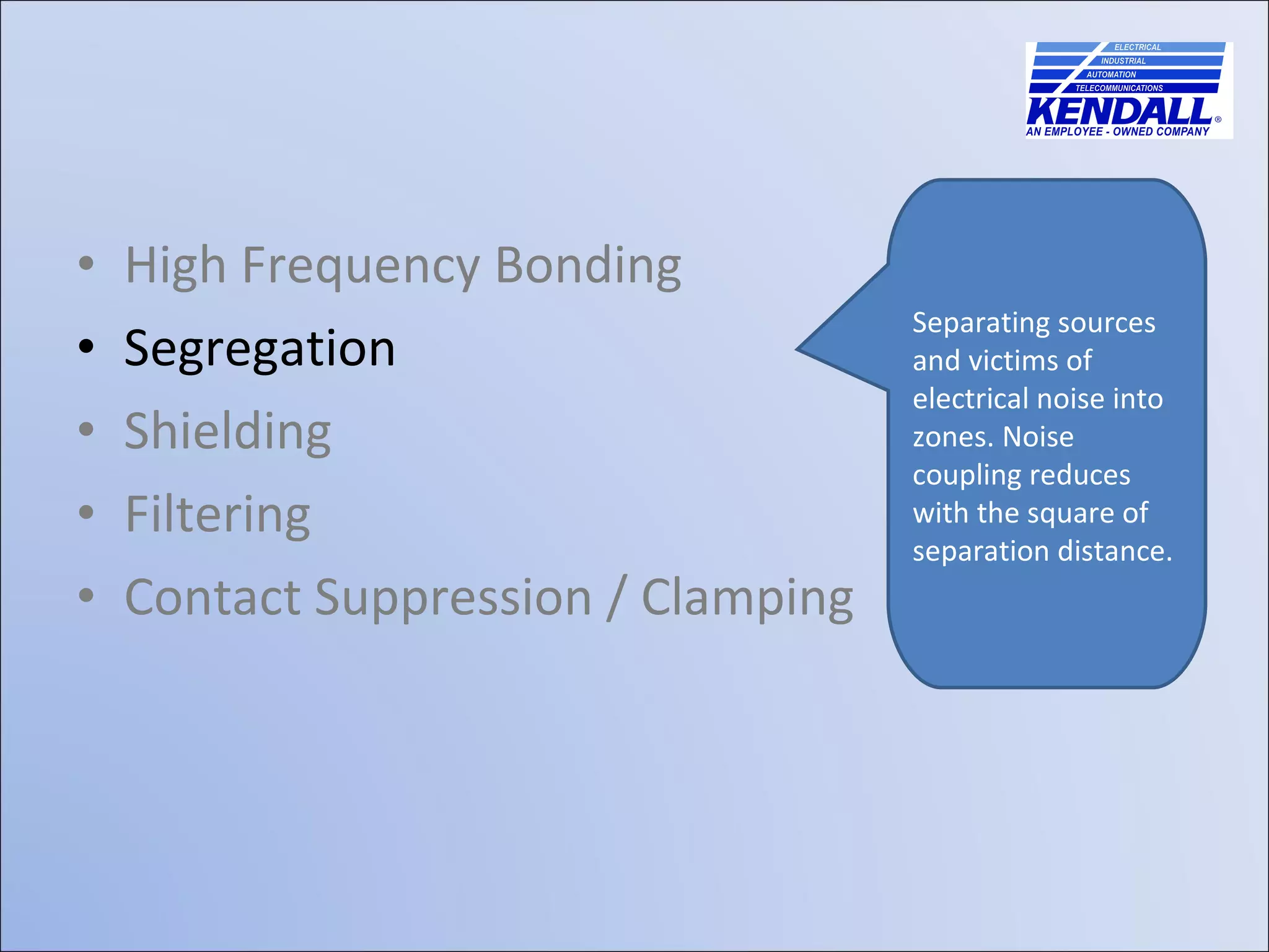
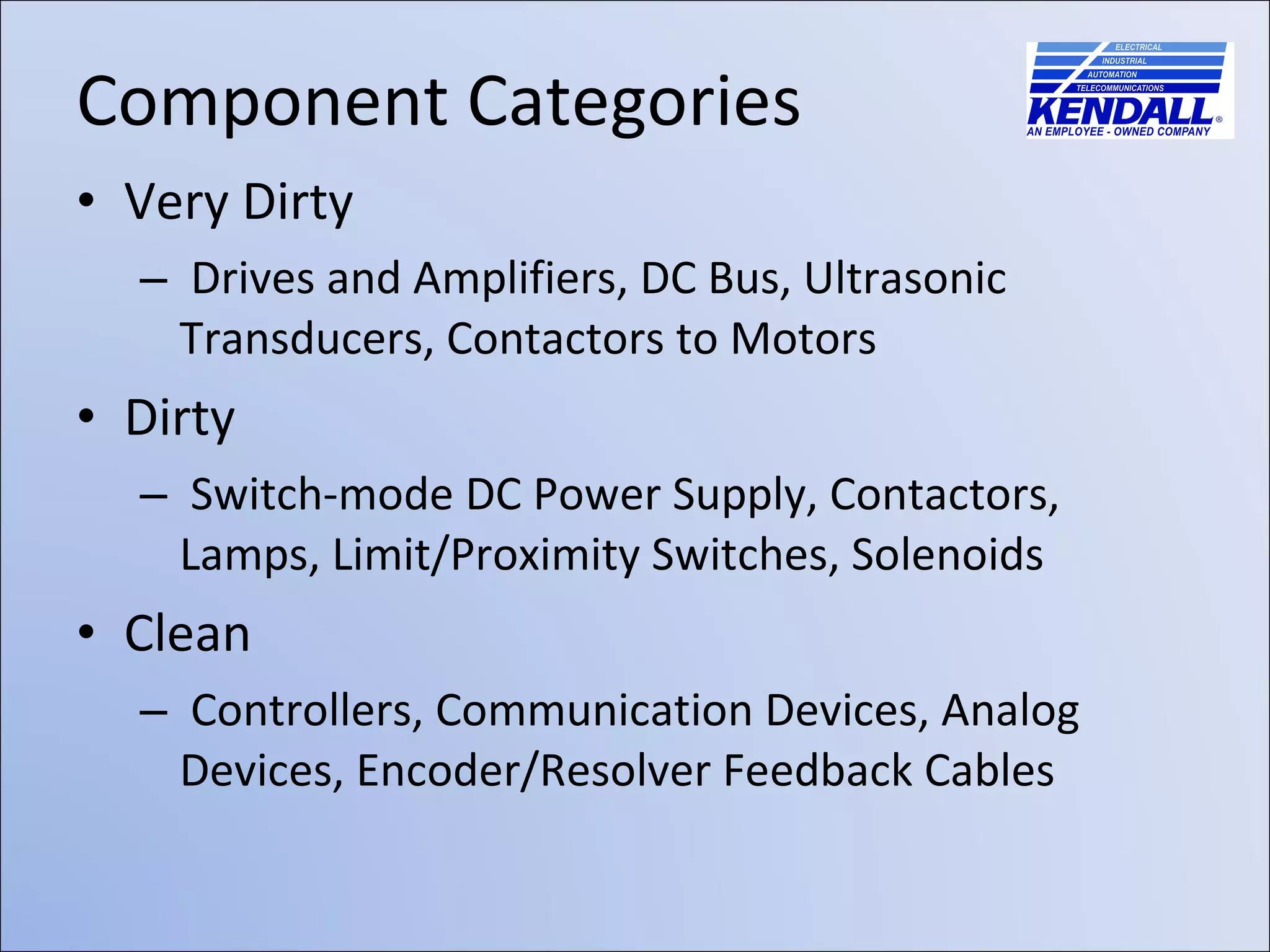
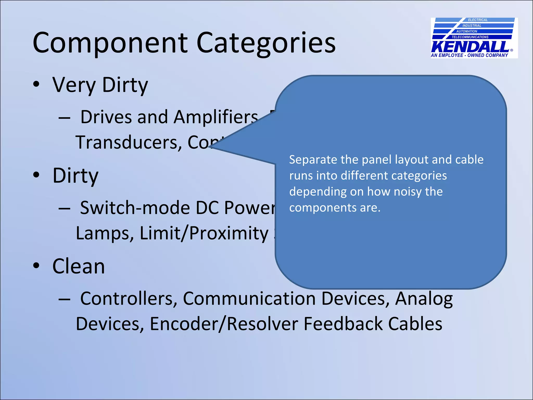
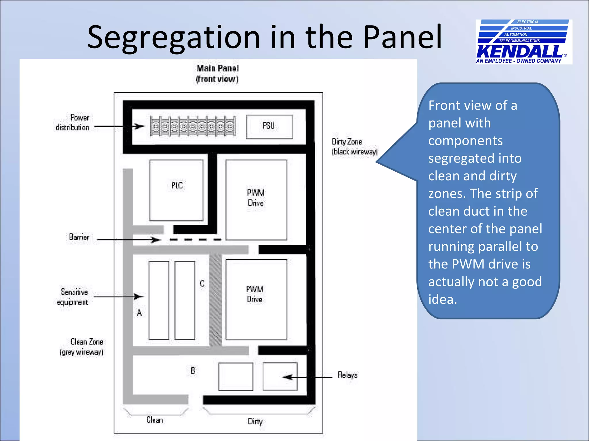

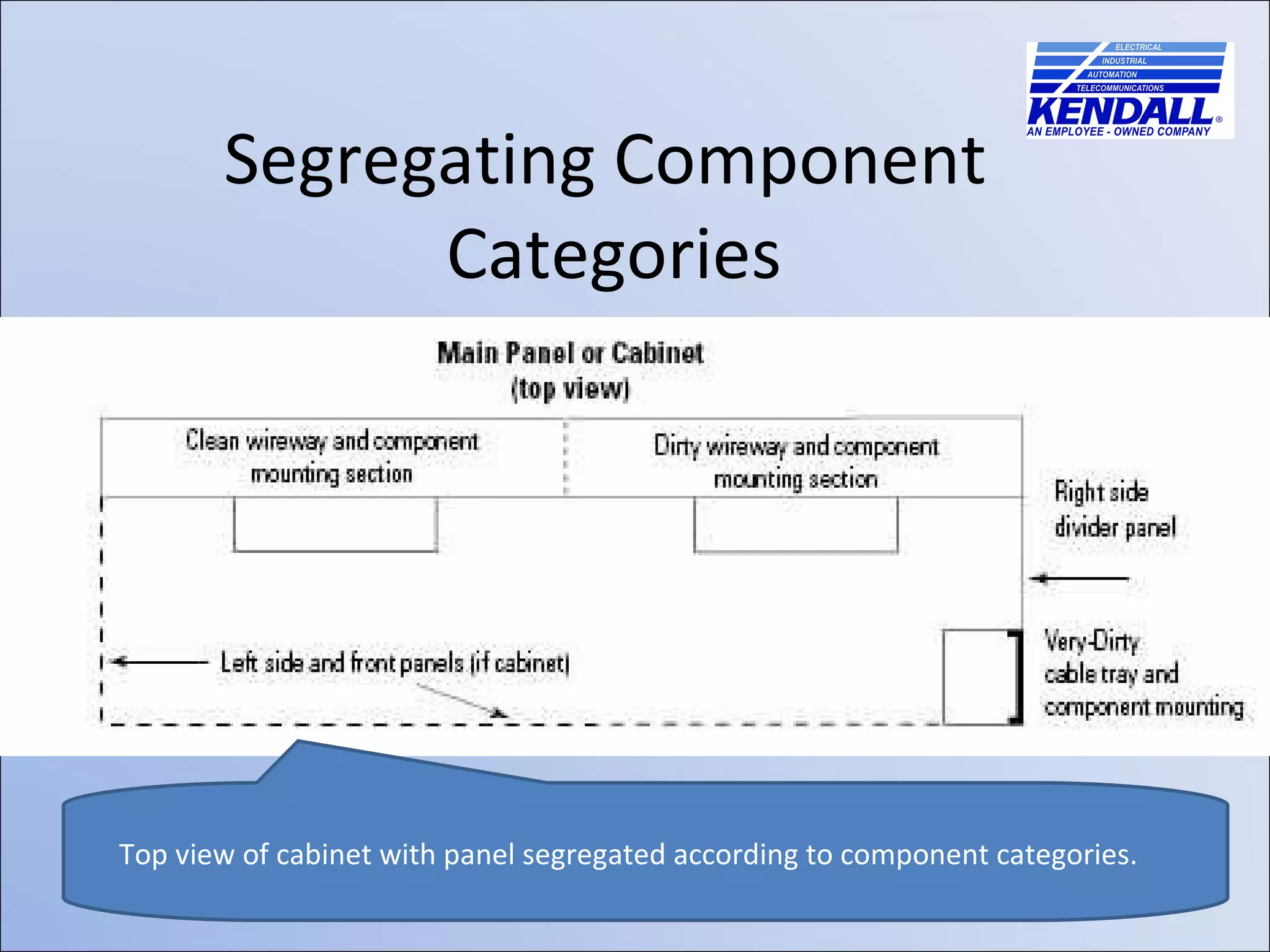
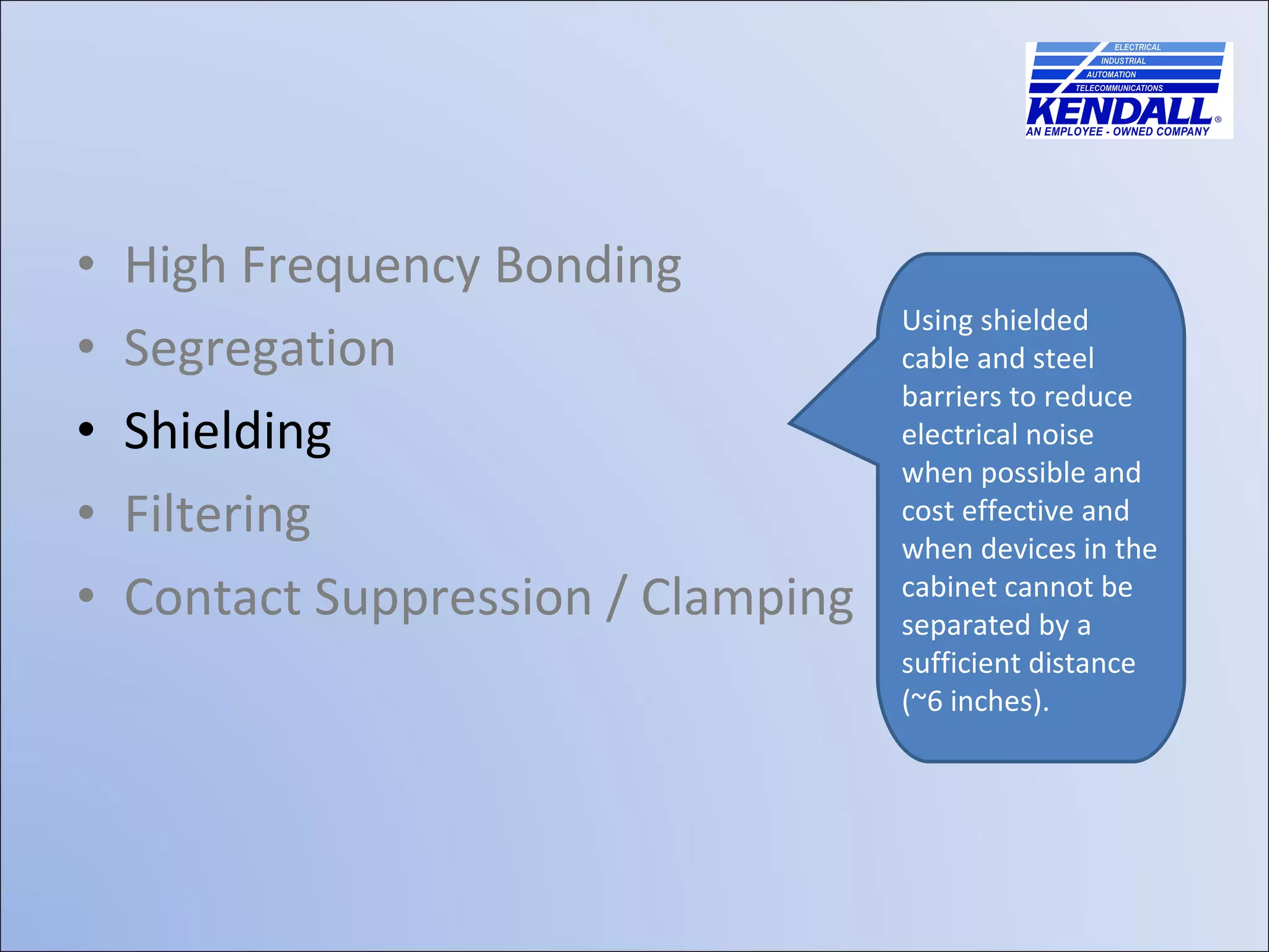
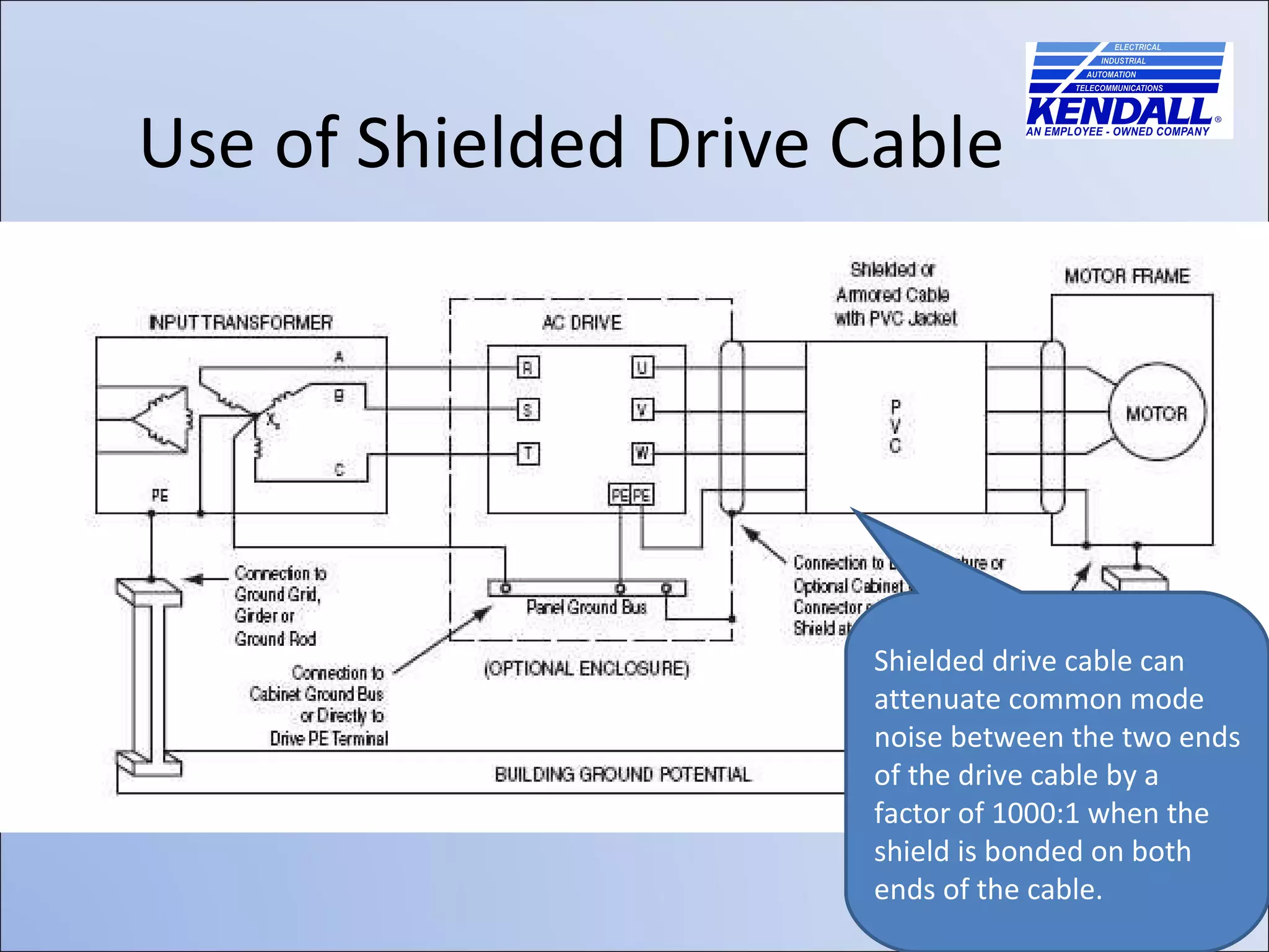
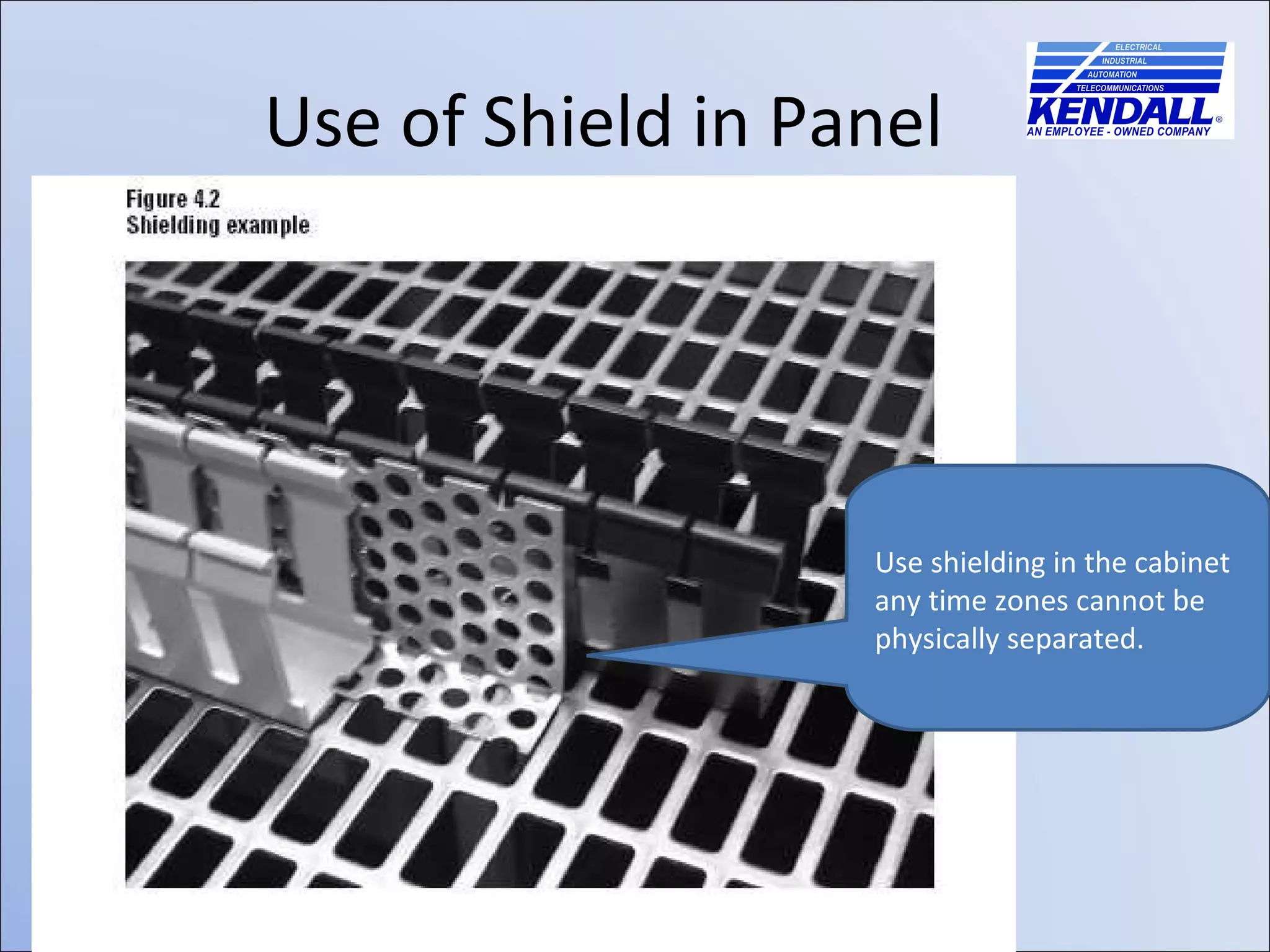
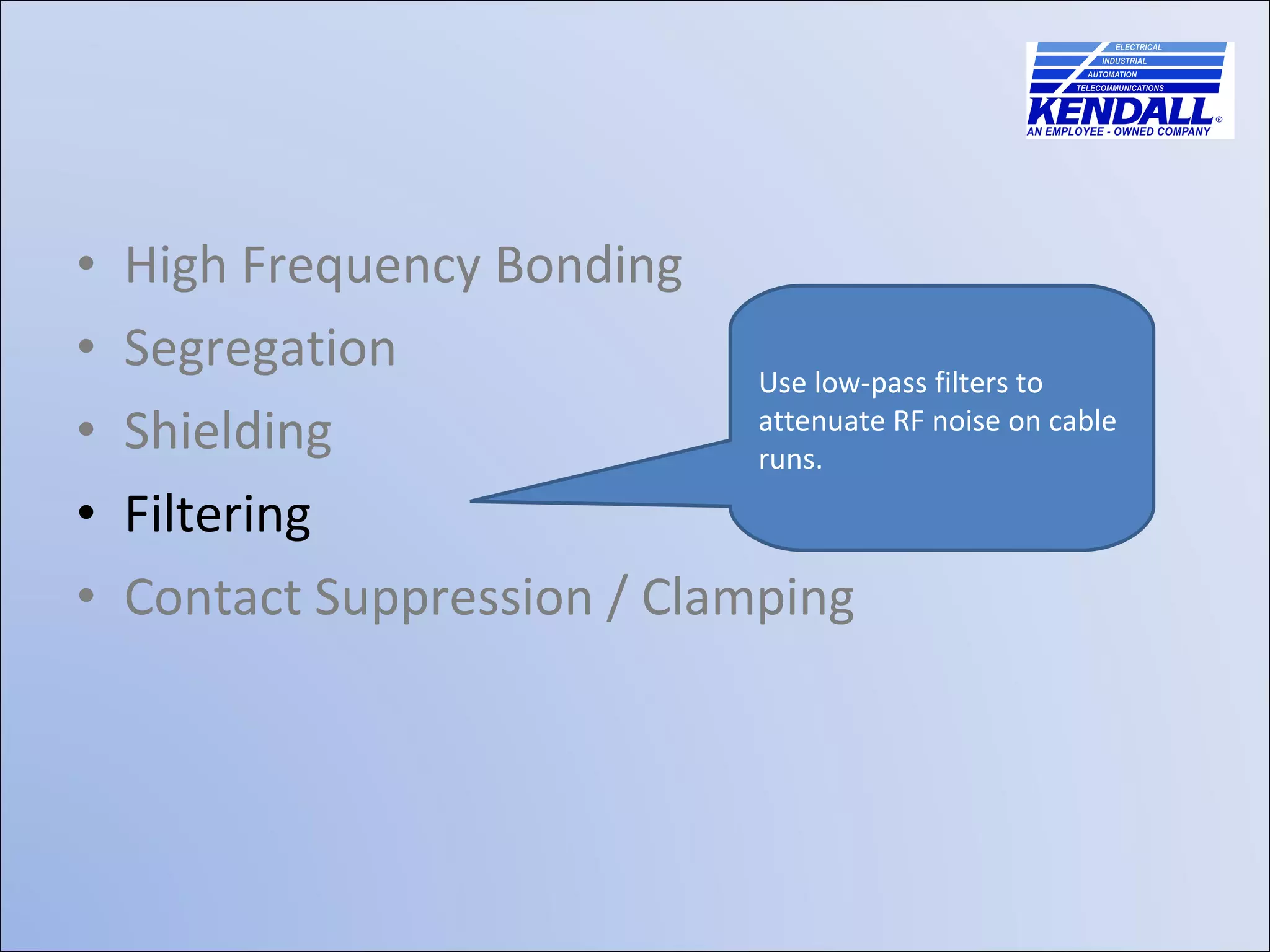
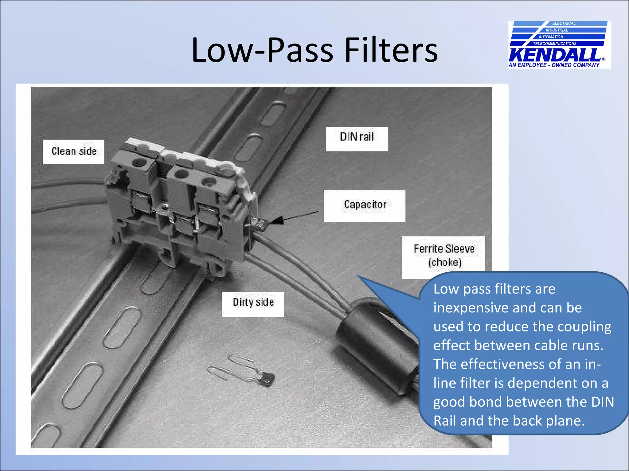
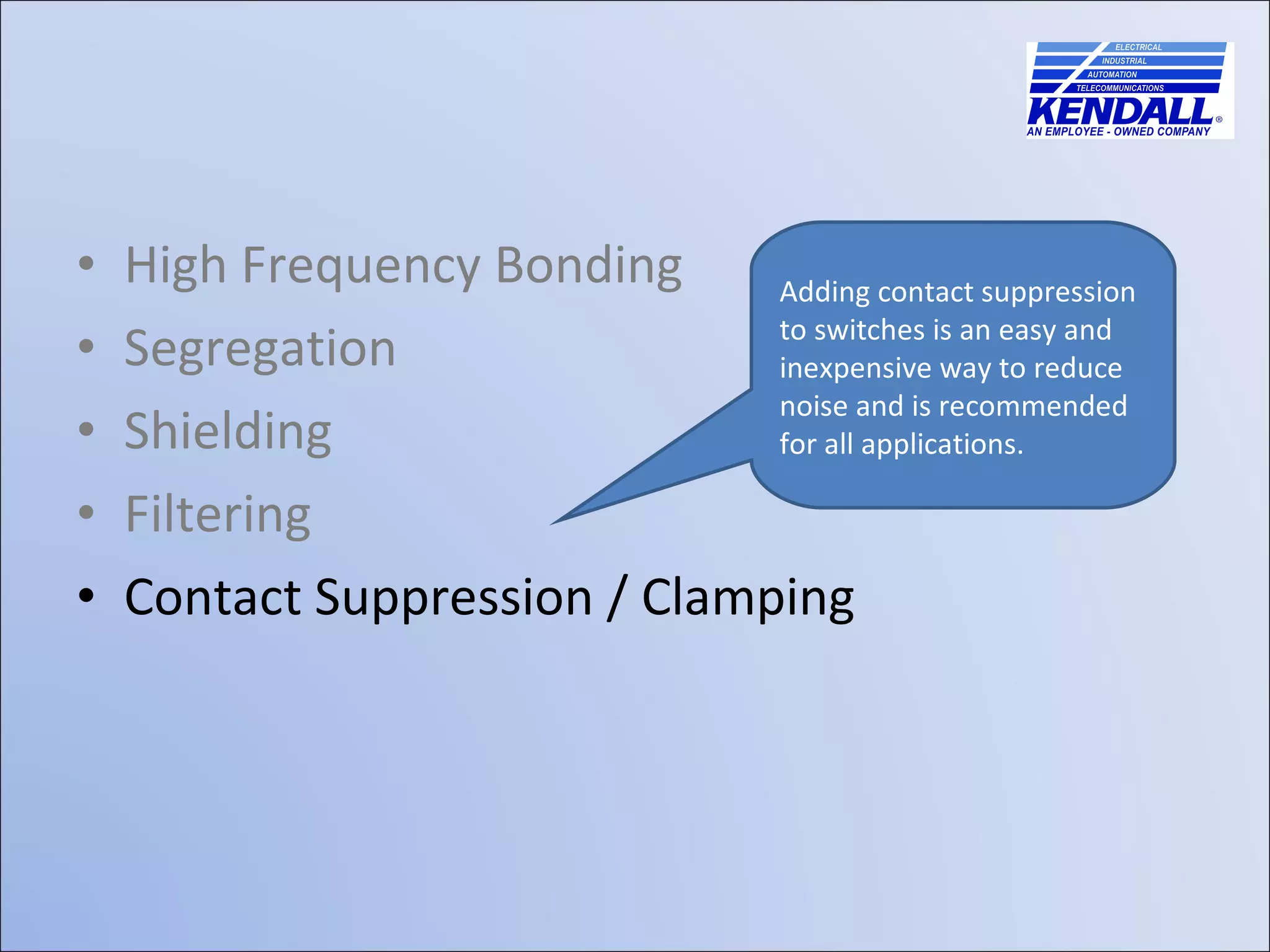


The document discusses best practices for minimizing electrical noise in control panels. It covers techniques like high frequency bonding, segregating noisy components, shielding, filtering, and contact suppression. Proper grounding and bonding helps ensure all metalwork is at the same electrical potential to reduce common mode noise, while techniques like shielded cables and physical separation of components can shield noise victims from noise sources.