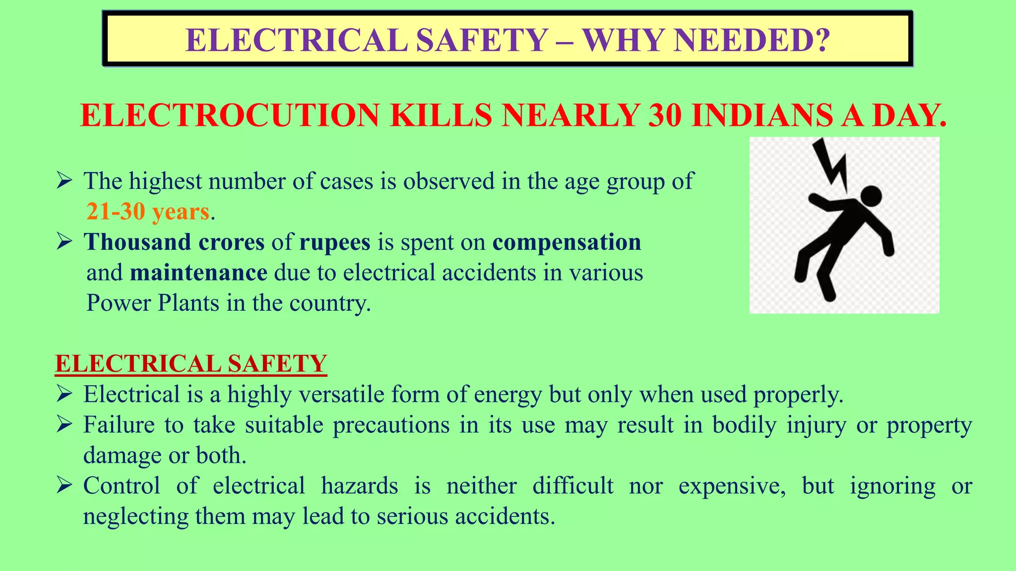
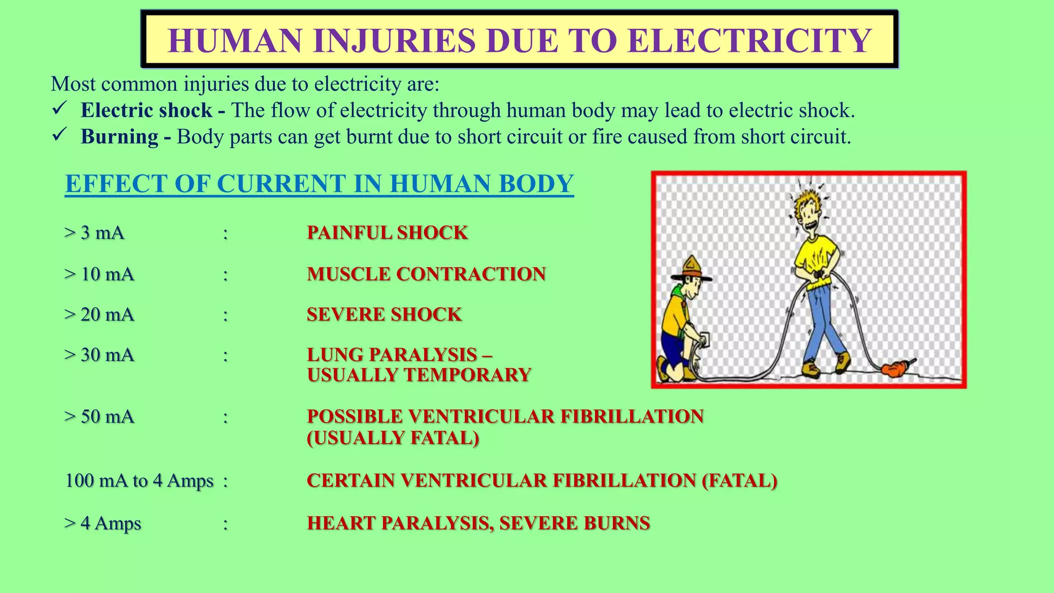
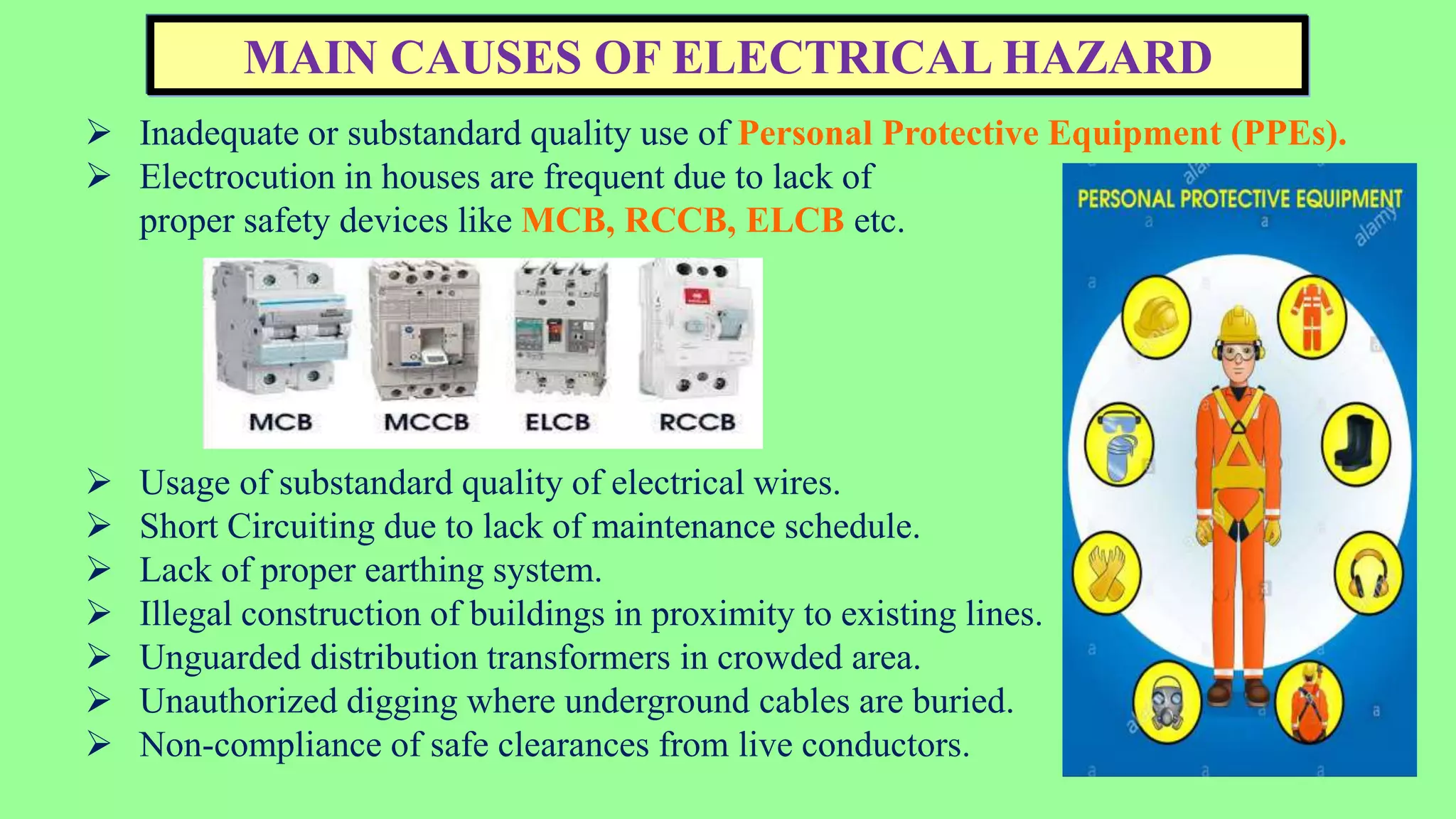
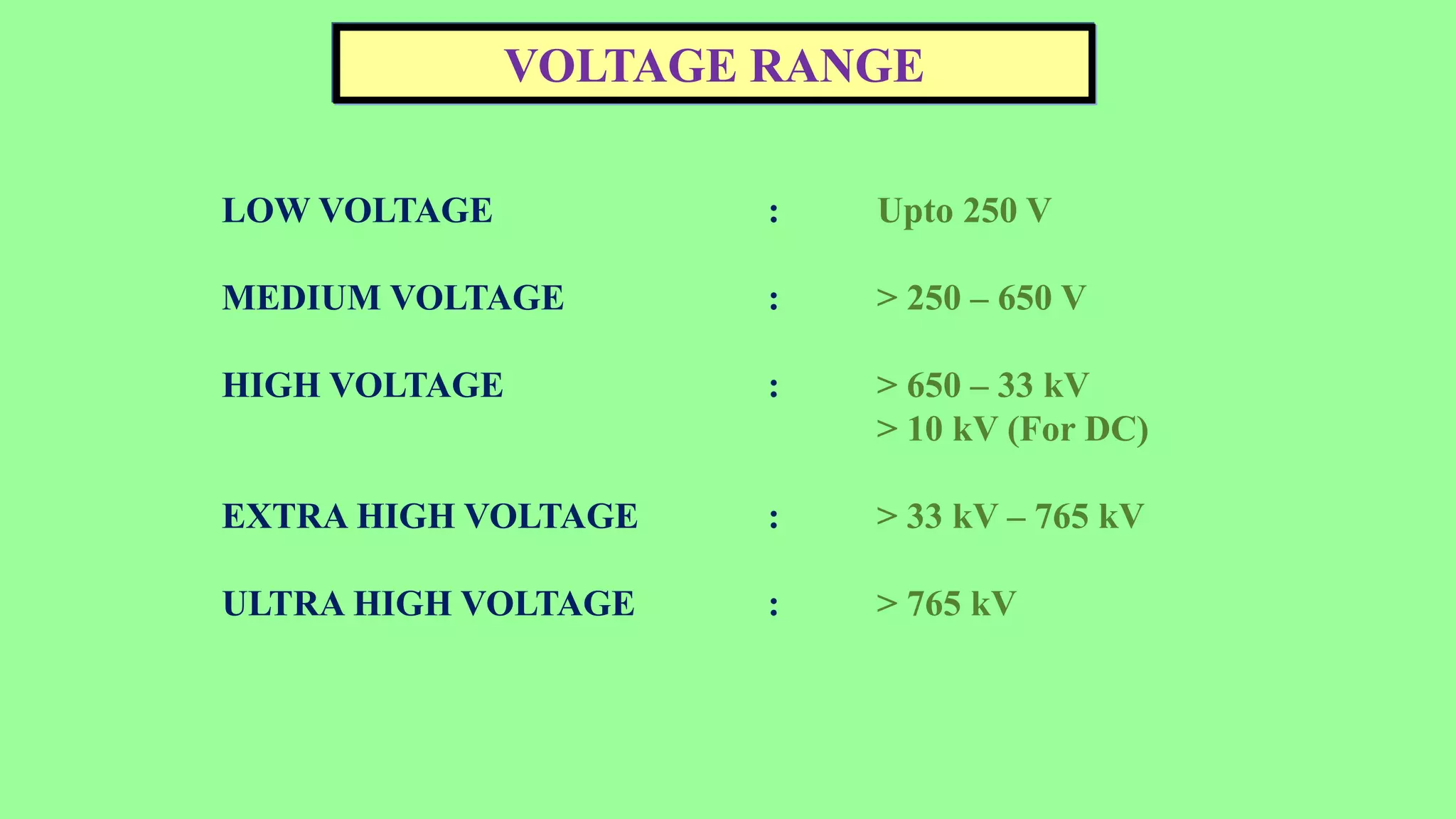
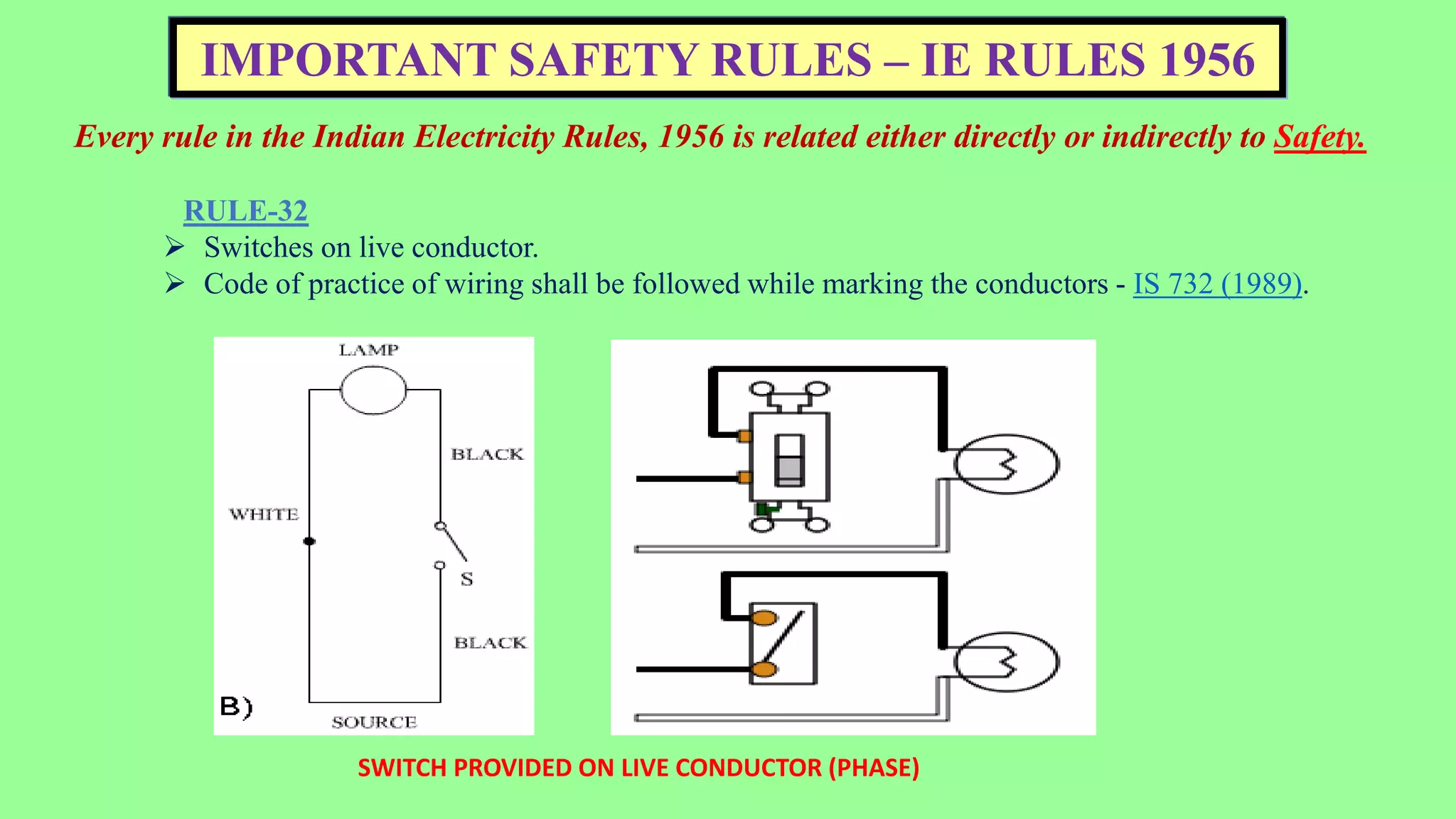
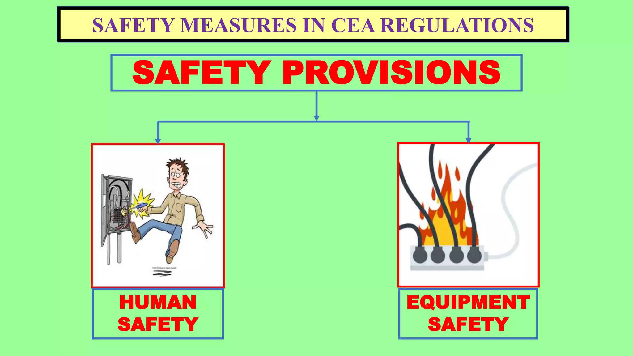
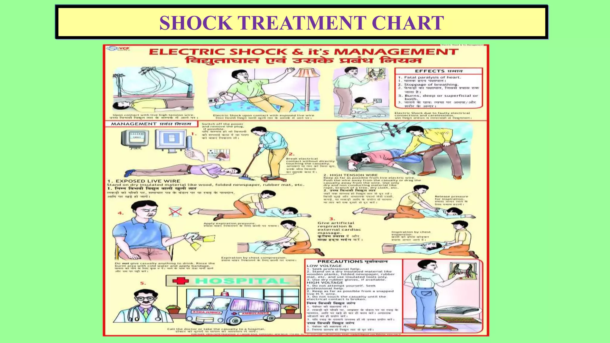
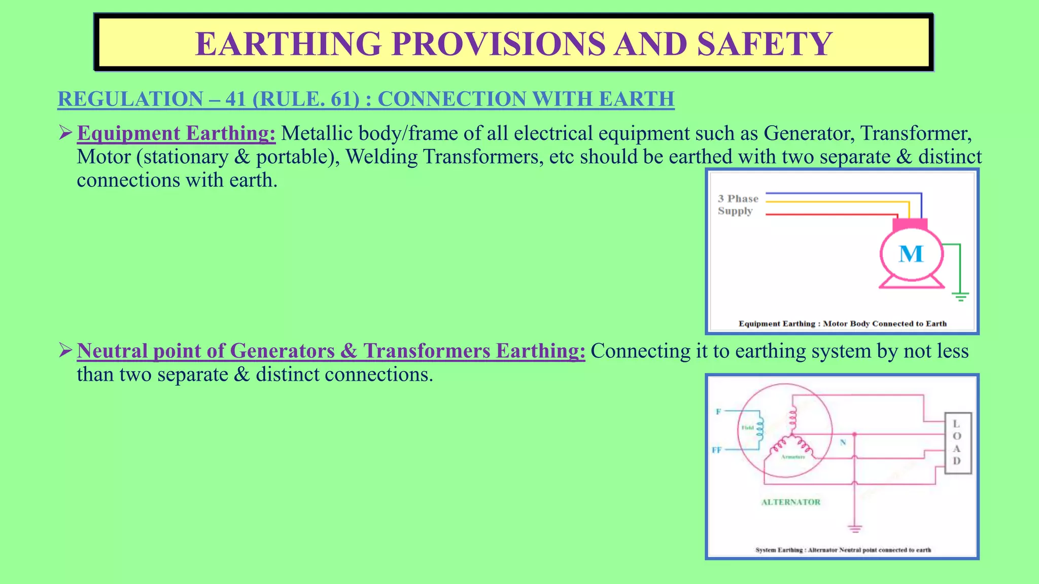
2. ELECTRICAL SAFETY – WHY NEEDED?
ELECTROCUTION KILLS NEARLY 30 INDIANS A DAY.
The highest number of cases is observed in the age group of
21-30 years.
Thousand crores of rupees is spent on compensation
and maintenance due to electrical accidents in various
Power Plants in the country.
ELECTRICAL SAFETY
Electrical is a highly versatile form of energy but only when used properly.
Failure to take suitable precautions in its use may result in bodily injury or property
damage or both.
Control of electrical hazards is neither difficult nor expensive, but ignoring or
neglecting them may lead to serious accidents.
3. HUMAN INJURIES DUE TO ELECTRICITY
Most common injuries due to electricity are:
Electric shock - The flow of electricity through human body may lead to electric shock.
Burning - Body parts can get burnt due to short circuit or fire caused from short circuit.
EFFECT OF CURRENT IN HUMAN BODY
> 3 mA : PAINFUL SHOCK
> 10 mA : MUSCLE CONTRACTION
> 20 mA : SEVERE SHOCK
> 30 mA : LUNG PARALYSIS –
USUALLY TEMPORARY
> 50 mA : POSSIBLE VENTRICULAR FIBRILLATION
(USUALLY FATAL)
100 mA to 4 Amps : CERTAIN VENTRICULAR FIBRILLATION (FATAL)
> 4 Amps : HEART PARALYSIS, SEVERE BURNS
4. MAIN CAUSES OF ELECTRICAL HAZARD
Inadequate or substandard quality use of Personal Protective Equipment (PPEs).
Electrocution in houses are frequent due to lack of
proper safety devices like MCB, RCCB, ELCB etc.
Usage of substandard quality of electrical wires.
Short Circuiting due to lack of maintenance schedule.
Lack of proper earthing system.
Illegal construction of buildings in proximity to existing lines.
Unguarded distribution transformers in crowded area.
Unauthorized digging where underground cables are buried.
Non-compliance of safe clearances from live conductors.
5. VOLTAGE RANGE
LOW VOLTAGE : Upto 250 V
MEDIUM VOLTAGE : > 250 – 650 V
HIGH VOLTAGE : > 650 – 33 kV
> 10 kV (For DC)
EXTRA HIGH VOLTAGE : > 33 kV – 765 kV
ULTRA HIGH VOLTAGE : > 765 kV
6. CONSTITUTION OF CEA
CENTRAL ELECTRICITY AUTHORITY (CEA) is a statutory organization
constituted under section 3(1) of Electricity Supply Act 1948, which has been superseded
by section 70(1) of The Electricity Act 2003.
CEA advises the government on policy matters and formulates plans for the development
of electricity systems.
Regulate measures relating to SAFETY and ELECTRIC SUPPLY in India.
Website: cea.nic.in
7. IMPORTANT SAFETY RULES – IE RULES 1956
Every rule in the Indian Electricity Rules, 1956 is related either directly or indirectly to Safety.
RULE-32
Switches on live conductor.
Code of practice of wiring shall be followed while marking the conductors - IS 732 (1989).
SWITCH PROVIDED ON LIVE CONDUCTOR (PHASE)
8. IMPORTANT SAFETY RULES – IE RULES 1956
RULE-35 : DANGER NOTICES.
The owner of every medium, high and extra-high voltage installation shall affix permanently in a
conspicious position a danger notice in Hindi or English and the local language of the district, with a
sign of skull and bones of a design as per the relevant standards.
9. IMPORTANT SAFETY RULES – IE RULES 1956
RULE-50
Energy shall not be supplied, transformed, converted or used unless the following
provisions are observed,
A suitable linked switch or circuit breaker is erected at the secondary side of the
transformer.
Every circuit is protected by a suitable cut-out.
Supply to each motor or group of motors is controlled by a linked switch or
circuit breaker.
Adequate precautions are taken to ensure that no live parts are exposed.
PROTECTION RELAY CIRCUIT
FAULT CURRENT PATH THROUGH HUMAN BODY MOTOR PROTECTION CIRCUIT
10. SPECIAL PROVISIONS IN HV & EHV INSTALLATIONS
RULE-63
Approval of Inspector is necessary before energizing any high voltage installations.
RULE-64
All apparatus and equipment intended to be used at high or extra high voltage shall be inaccessible except to an
authorized person.
A suitable segregation shall be provided for licensee’s equipment.
A suitable soak pit or arrangement to drain out the leaked oil shall be made in sub-stations where the transformers
are provided.
Cable trench shall be filled with sand or other non-flammable material and covered by bricks.
TRANSFORMER OIL SOAK PIT
CABLE TRENCH FILLED WITH SAND
11. SPECIAL PROVISIONS IN HV & EHV INSTALLATIONS
RULE-65
The installation must be subjected to the prescribed testing before energizing.
RULE-66
Conductors shall be enclosed in a metallic covering and suitable circuit breakers shall be provided to
protect the equipment from overloading.
RULE-68
In case of outdoor type of sub-station, a metallic fencing of not less than 1.8 m height shall be erected
around the transformer.
METALLIC FENCING AROUND TRANSFORMER
12. SAFETY MEASURES IN CEA REGULATIONS
SAFETY PROVISIONS
HUMAN
SAFETY
EQUIPMENT
SAFETY
13. HUMAN SAFETY
SALIENT POINTS
Register of designated persons to be maintained properly and kept up to date.
Panel enclosures shall be made fire-proof.
Switches on live conductors.
Direct line on neutral in 1ɸ supply.
Green wire in earthing line.
ELCB/RCCB in each circuit.
Display of “Danger notice” in local language/Hindi.
Insulating floor mats before switchgear panels.
Identification of front & rear panels.
Placement of Fire buckets filled with sand/Fire extinguishers and First Aid boxes with proper
marking at convenient places. Also, First Aid training to be provided.
Flexible cables to be used for portable or transportable equipment.
Display of Shock Treatment Chart at conspicuous places.
Minimum 100 cms clear space in front of switchboard and 75 cms space behind the board.
Proper identification and distinguishing between live and neutral conductor.
Trenches inside Sub-station to be filled with non-inflammable material.
Baffle walls of 4 hours fire rating to be provided around power transformer.
Fencing of 1.8 mtrs or more height around Sub-station. Handrails to be earthed.
Overhead conductor clearances to be maintained.
Earthing of guard & stay wires.
Clearances from different regulatory bodies.
15. EQUIPMENT SAFETY
SALIENT POINTS
Measurement of earth resistance twice a year.
Neutral of generator and transformers to be earthed at two different points.
Motor and metallic coverings earthing at two different points.
Testing of earth electrodes.
Regular checking of all protections & interlocks.
Periodic testing of transformer oil samples.
Protection checking of transformers and its lightning arrestors.
Healthiness checking of all EHV equipment at regular intervals.
RLA (Residual Life Assessment) study of old equipment (> 20 years).
Record maintenance of Routine & Factory tests of equipment.
Oil soak pits for transformers with oil capacity > 2000 litres.
Separate cable trays for AC/DC/Control/Power cables.
Horizontal clearances to be maintained between overhead conductors
considering wind pressure.
16. REGULATION – 41 (RULE. 61) : CONNECTION WITH EARTH
Earthing by minimum two separate & distinct connections with minimum two
different earth electrodes.
Earth electrodes shall be inter connected to reduce the earth resistance.
Neutral conductor shall also be earthed at one or more points along with
distribution system or service line.
System supply by concentric cable, external conductor earthed by separate &
distinct connections.
Minimum two or more earth pits to be made to ensure proper grounding of the system.
EARTHING PROVISIONS AND SAFETY
17. EARTHING PROVISIONS AND SAFETY
REGULATION – 41 (RULE. 61) : CONNECTION WITH EARTH
Equipment Earthing: Metallic body/frame of all electrical equipment such as Generator, Transformer,
Motor (stationary & portable), Welding Transformers, etc should be earthed with two separate & distinct
connections with earth.
Neutral point of Generators & Transformers Earthing: Connecting it to earthing system by not less
than two separate & distinct connections.
18. EARTHING PROVISIONS AND SAFETY
REGULATION – 41 (RULE. 61) : CONNECTION WITH EARTH
Protective Frame/Conduit/Junction box Earthing: All metallic junction box, metal casing, metallic
covering throughout the length & 3rd pin of socket shall be earthed up to 250V.
Rule. 61(5)-Measurement of Earth resistance: Earthing resistance shall be measured on dry day
during dry season not less than once in two years.
CONDUIT EARTHING JUNCTION BOX EARTHING
19. REGULATION – 42 (RULE. 61A) : PROVISION OF ELCB
All LV installations (Up to 250 V) of 5 kW & above rating shall be controlled by earth leakage
protective device to disconnect supply instantly of earth fault or leakage.
REGULATION – 47 : EARTHING OF METAL SHEATHED ELECTRIC SUPPLY LINE
Earthing of metal sheathed electric supply line other than overhead lines voltage exceeding 650V,
outer metal sheathing shall be earthed.
EARTH LEAKAGE PROTECTIVE DEVICE
ELCB
METAL SHEATHED CABLE
20. APPARATUS EARTHING – STEP & TOUCH POTENTIAL
REGULATION – 48 : VOLTAGE EXCEEDING 650 V.
All not carrying current metallic part of the associate installation of voltage exceeding 650 V shall be earthed to a
grounding system or mat,
i) Limit to touch the Step & Touch potential.
ii) Limit to ground potential rise to tolerable values
so as to prevent danger due to transfer of potential
through ground, earth wires, cable sheath, fences etc.
iii) Maintain the resistance of earth connection to such a
value as to make operation of protective device effective.
For a Fault current of level 32 kA, the typical value of
Touch potential is 640 V.
Step potential is 1600 V.
Gravel Resistance ≈ 20 kΏ.
Generator & Transformer neutral shall be earthed through
suitable impedance by not less than two separate & distinct connections.
21. APPARATUS EARTHING
REGULATION – 48 : VOLTAGE EXCEEDING 650 V.
For Generating Station, Sub Station and Industrial installations of more than 33 kV, neutral & frame shall be earthed
with common earthing grid/mat to rise to tolerable values for Step & Touch potential.
Single phase system voltage more than 650V shall have effective earthing.
EARTHING GRID / MAT
22. EARTHING
REGULATION – 72 : METALLIC FITTINGS AND SUPPORTS OF OVERHEAD LINES.
All metallic fittings & supports shall be earthed in 3 points in every kilometre.
Stay wire shall be earthed.
REGULATION – 90 : EARTHING OF GUARD WIRE.
Every guard wire shall be earthed at each point at which its electrical continuity as broken & shall also be
connected with rails at intervals of not more than 5 spans.
GUARD WIRE PLACED BELOW OVERHEAD LINE
EARTHING OF STAY WIRE
EARTHING OF TRANSMISSION TOWER
23. IMPORTANT ELECTRICAL SAFETY PRECAUTIONS
Never touch or try repairing any electrical equipment or circuits with wet hands. It increases the conductivity of the electric
current.
Do not use equipment with frayed cords, damaged insulation or broken plugs.
Always turn off the mains while working on any receptacle. Put a “Danger” sign at the point of isolation.
Use insulated tools while working.
Use appropriate insulated rubber gloves and goggles while working on any branch circuit or any other electrical circuit.
Never try repairing energized equipment. Always check that it is de-energized first by using a tester or non-contact voltage
detector.
Know the wire code of your country.
Read and follow manufacturer’s instructions for safe use of electrical equipment.
Leave work on energized equipment to qualified workers.
Check electrical connections to make sure they are tight.
Keep machines and other electrical equipment clean and well lubricated.
Report electrical problems immediately.
Do not use temporary wiring.
Use proper electrical PPEs before starting any work in an electrical circuit or equipment.
Apply for right “Permit to Work” prior to maintenance activity on an electrical system.
Do not wear metal jewelry when working with electrical equipment.
Do not run cords along the floor.
Never overload motors, circuits, or outlets.
Safety Initiatives by EMD -VSTPS
NON CONTACT VOLTAGE DETECTOR
24. SWITCH FUSE UNIT (SFU)
It has one switch unit and one fuse unit. When we give ON
command, the contacts will get closed through switch and then
the supply will pass through the fuse unit to the output.
It is very widely used for low and medium voltages. The
ratings of switch fuse units are in the range of 30, 60, 100, 200,
400, 600 and 800 Amperes. Switch fuse units can be installed
on metal-clad switchgear.
It is specially used for high capacity tripping.
Whereas MCB & MCCBs are used for low capacity tripping.
Switch Fuse Unit can only provide overcurrent protection.
there is no separate switch and fuse unit. There is only the fuse
unit which itself acts as a switch.
SWITCH FUSE UNIT
FUSE SWITCH UNIT
25. COMMON ELECTRICAL PROBLEMS
Motor not taking start.
Motor overload.
Motor tripping on protection.
Breaker not racking in/out.
MCC disturbance.
Motor abnormal sound.
Motor bearing and body getting hot.
Cable heating / joint failure.
27. HT SWITCHGEAR - CONTROL SUPPLY CHECKING
REPORTED DEFECT
MOTOR NOT TAKING START.
MCC DISTURBANCE.
TYPE OF JOB
CHECKING OF START PERMISSIVE
CIRCUIT.
CHECKING OF CONTROL FUSE.
CHECK FOR ANY OTHER PROTECTION.
PPEs TO BE USED
ARC SUIT.
ARC FLASH HOOD.
NON-CONTACT VOLTAGE DETECTOR.
INSULATED TOOL KIT.
ELECTRICAL SAFETY SHOE.
28. LT SWITCHGEAR - CONTROL SUPPLY CHECKING
REPORTED DEFECT
MOTOR NOT TAKING START.
MOTOR TRIPPING ON PROTECTION.
MCC DISTURBANCE.
TYPE OF JOB
CHECKING OF START PERMISSIVE
CIRCUIT.
CHECKING OF CONTROL FUSE.
CHECKING OF OVERLOAD RELAY.
CHECK FOR ANY OTHER PROTECTION.
PPEs TO BE USED
ARC SUIT.
ARC FLASH HOOD.
NON-CONTACT VOLTAGE DETECTOR.
INSULATED TOOL KIT.
ELECTRICAL SAFETY SHOE.
29. LT BREAKER - MECHANISM CHECKING
REPORTED DEFECT
MOTOR NOT TAKING START.
BREAKER NOT RACKING IN/OUT.
TYPE OF JOB
CHECKING OF CIRCUIT BREAKER
MECHANISM.
PPEs TO BE USED
ARC SUIT.
ARC FLASH HOOD.
INSULATED TOOL KIT.
ELECTRICAL SAFETY SHOE.
30. LT MODULE - CONTROL SUPPLY CHECKING
REPORTED DEFECT
NOT TAKING COMMAND.
TRIPPING ON OVERLOAD.
MCC DISTURBANCE.
TYPE OF JOB
CHECKING OF POWER FUSE.
CHECKING OF CONTROL FUSE.
CHECKING OF OVERLOAD RELAY.
PPEs TO BE USED
ARC SUIT.
ARC FLASH HOOD.
NON-CONTACT VOLTAGE DETECTOR.
INSULATED TOOL KIT.
INSULATED FUSE PULLER.
ELECTRICAL SAFETY SHOE.
31. HT BREAKER – ISOLATION / NORMALISATION
TYPE OF JOB
CIRCUIT BREAKER RACK IN/OUT.
PPEs TO BE USED
ARC SUIT.
ARC FLASH HOOD.
ARC FLASH GLOVE.
ELECTRICAL SAFETY SHOE.
32. LT BREAKER – ISOLATION / NORMALISATION
TYPE OF JOB
CIRCUIT BREAKER RACK IN/OUT.
PPEs TO BE USED
ARC SUIT.
ARC FLASH HOOD.
ARC FLASH GLOVE.
ELECTRICAL SAFETY SHOE.
33. LIGHTING MODULE - CHECKING
REPORTED DEFECT
LIGHTS NOT GLOWING.
PROVISION OF ADDITIONAL LIGHTING
SUPPLY.
TYPE OF JOB
CHECKING OF LIGHTING MODULE.
POWER CABLE CONNECTION/
DISCONNECTION.
PPEs TO BE USED
ARC SUIT.
ARC FLASH HOOD.
NON-CONTACT VOLTAGE DETECTOR.
INSULATED TOOL KIT.
ELECTRICAL SAFETY SHOE.
34. LIGHTING PANEL (NLP) – CHECKING
REPORTED DEFECT
LIGHTS NOT GLOWING.
TYPE OF JOB
CHECKING OF CONTACTOR.
CHECKING OF POWER SUPPLY CIRCUIT.
PPEs TO BE USED.
NON-CONTACT VOLTAGE DETECTOR.
INSULATED TOOL KIT.
INSULATED GLOVE.
ELECTRICIAN SAFETY HELMET.
ELECTRICAL SAFETY SHOE.
35. HOT LINE MAINTENANCE
SUB-REGULATION (3) OF REGULATION – 19 :
IMPORTANT SAFETY PRECAUTIONS
Only trained personnel are designated to do the work.
Work permit to be taken from terminal stations of each end of
transmission line.
Work shall be performed with proper planning and clarity.
Hotline job must be carried out in sunny weather.
All equipment and tools shall be inspected and checked for correct
operation.
Auto re-closure shall be in 'OFF' position for the line at both ends.
Hot sticks and other assemblies shall be kept on hotline tool rack to
avoid ground contact.
Helmet, safety shoes and safety belt shall compulsorily be used.
No live-line team members on the tower and conductor shall
wear any metallic chain, wristwatch or ring to avoid any circulating current.
The team line-men will wear conductive socks, boots, helmets and hand gloves.
Tarpaulin sheet should be laid on the work area .
A light vehicle shall be kept nearby during entire work period.
HOT LINE WORK IN 400 KV CONDUCTOR.
36. ELECTRICAL SAFETY OFFICER
All suppliers of electricity including generating companies, transmission companies and
distribution companies shall designate an Electrical Safety Officer for ensuring observance
of safety measures.
QUALIFICATION
The Electrical Safety Officer shall be an Electrical Engineering degree holder with at least
five years of experience in operation and maintenance of electrical installations.
RESPONSIBILITY
The Electrical Safety Officer designated under, sub-regulation (1), shall carryout periodic
tests as per the relevant standards and inspection of such installations for ensuring
observance of safety measures specified under these regulations at intervals not exceeding
one year, and keep a record thereof in Form I or Form II or Form III, as the case may be,
of Schedule IV and test reports, and also keep a register of recommended safety
requirements duly acknowledged by the owner with date and compliances thereafter; and
such records shall be made available to the Electrical Inspector, as and when required.
37. FORMS FOR INSPECTION REPORT
The designated Electrical Safety Officer shall fill the following forms to
carry out the periodic tests at regular interval:
Form I – For installations up to 250 V.
Form II – For installations more than 250 V and up to 650 V.
Form III – For installations exceeding 650 V.