Downloaded 358 times


![Types of Glass, Properties and Uses
11
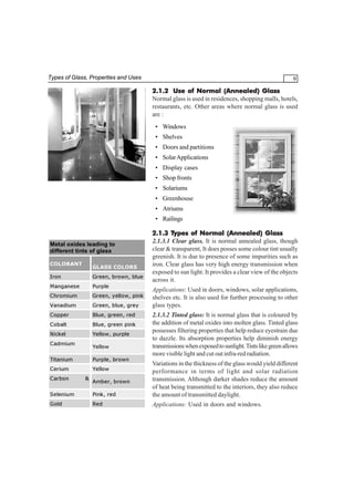
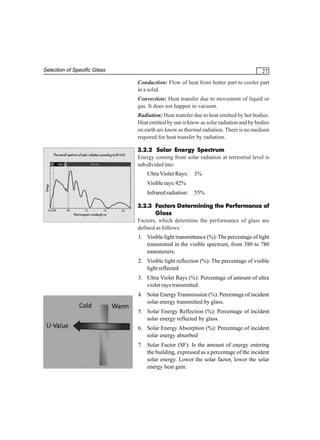
2.2 LAMINATED GLASS
Laminated glass is composed of two or more layers of
glass with one or more layers of a transparent/ pigmented
and specially treated plastic Polyvinyl Butyral [PVB]
sandwiched between the glass layers. The glass panes
(layers) can be either normal glass or tempered glass. When
the glass is broken, fragments tend to adhere to the plastic
[PVB] interlayer thereby reducing the risk of injury and
helping to resist further damage by weather.
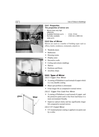
2.2.1 Properties
The properties of laminated glass are:
• Laminated glass does not shatter like ordinary glass. It
absorbs impact, resists penetration, and remains intact
even if broken, holding glass fragments in place and
lowering the risk of injury. Global building standards
increasingly specify stricter safety requirements where
any breakage could mean a major hazard from falling
glass and glass floors.
• Laminated glass resists intrusion because the interlayer
continues to safeguard the building even after the glass
itself is broken. It cannot be cut from only one sides,
so ordinary glasscutters are useless as break-in tools.
Laminated glass tends to resist impact. In multi-ply
configurations, it can even resist bullets, heavy objects,
or small explosions. In most cases, it takes many blows,
all in the same spot, to penetrate the glass. The rise in
urban crime and terrorism also points to laminated glass
as increasingly desirable material.
Laminated glass is capable to stop flying debris and
limit or avoid splintering on opposite side of the impact.
• Laminated glass is an excellent barrier to noise. The
sheer damping performance of the plastic interlayer
makes laminated glass an effective sound control
product. This makes it ideal for airports, hotels, dataprocessing centers, recording studios, and any building
near airports, highways, or train lines.
• Ultraviolet light is the leading cause of deterioration
and fading of furnishings, pictures, and fabrics.](https://image.slidesharecdn.com/glass-in-buildings-nkgarg-140101013212-phpapp02/85/Glass-in-buildings-nk-garg-28-320.jpg)

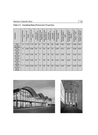
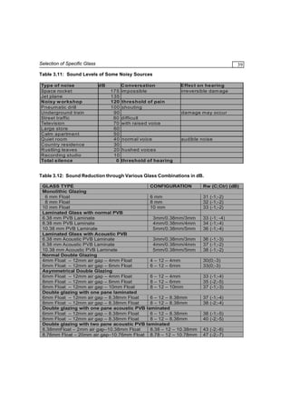

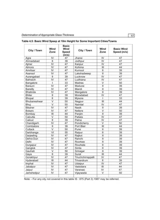
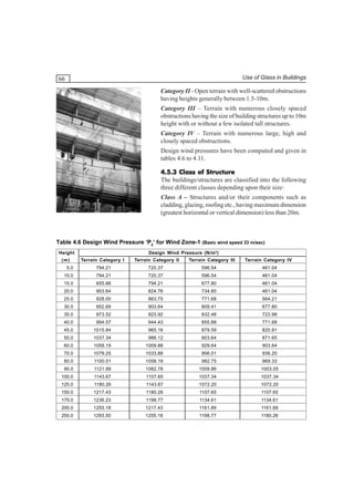
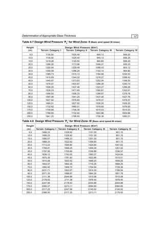
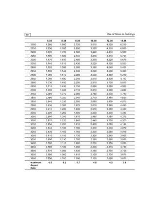
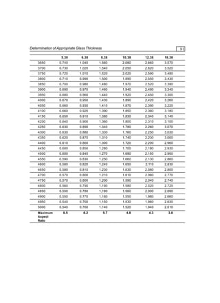
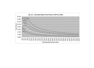
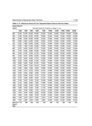
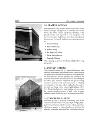


This document provides guidelines for using glass in buildings. It discusses various types of glass like annealed glass, laminated glass, tempered glass, heat strengthened glass, reflective glass, insulating glass units, and mirrors. It describes their properties and uses. The guidelines cover selection of appropriate glass type based on factors like heat gain, sound insulation, safety, strength and aesthetics. It also provides tools to determine the minimum required thickness of glass panels based on wind load calculations. Finally, it discusses common glazing systems and provides general guidelines for using glass in buildings.


